


Installation & Operating Instructions
DTAV40 Series Time Initiated, Temperature, Pressure or Time Terminated Auto-Voltage 40A Defrost Timers
 WARNING Risk of Fire or Electric Shock
•Disconnect power at the circuit breaker(s) or disconnect switch(es) before beginning installation or servicing. Do not use the off position of the timer for equipment servicing.
•More than one circuit breaker or disconnect switch may be required to de-energize the equipment before servicing.
•Use COPPER conductors ONLY.
•For 40 amp loads, use #8 AWG wire, rated 90 degrees C min.
•Wire in accordance with national and local electrical code requirements.
•This Type 3R enclosure does not provide grounding between conduit connections. When metallic conduit is used, you must also install grounding type bushings and jumper wire, in accordance withå the national electrical code requirements.
•When replacing a timer with a metal bracket, replace the bracket with a non-metallic bracket. (Intermatic Model DT-B is recommended.)
•For outdoor locations, raintight, or wet location, conduit hubs that comply with requirements of UL514B (standard for fittings for conduit and outlet boxes) are to be used.
NOTICE Risk of Damage to Timer
•Rotate timer dial clockwise only.
•Do not move the clock hands on the timer. Moving the clock hands can damage the timer.
SPECIFICATIONS:
Maximum Contact Switch Rating:
40A Resistive @ 120-240VAC 2HP @ 240VAC; 1HP @ 120VAC
WIRING CONNECTIONS:
Screw box lug terminals. Up to one #8AWG Wire
ENVIRONMENTAL RATINGS:
Operating Temperature Range: -40˚F to 104˚F (-40˚C to 40˚C)
Operating Humidity: 0 - 95% RH, non-condensing
ELECTRICAL LIFE:
50,000 Operations at Full Load
DIMENSIONS:
8.795" x 6.631" x 2.935" (H x W x D)
SHIPPING WEIGHT: 3 lbs. AGENCY APPROVALS: UL LISTED
Mode Selection Switch (S1) 

BRACKET MOUNT (Saleable item DT-B)
SEE Separate BRACKET REPLACEMENT NOTICE IN PACKAGE
UL TYPE 3R ENCLOSURE |
UL TYPE 1 ENCLOSURE |
Set Mode Selection (See S1 DIP Switch, table and instructions below).
MODE SELECTION (S1 DIP SWITCH):
First determine what model is being replaced (Grasslin or Competitors). The mode selector DIP switch (located at lower right side of the board) determines the configuration of terminals 2 & 4. In position “A”, the terminals are normally closed, and will open during a defrost. In position “B”, terminals 2 & 4 are normally open, and will close during a defrost. Select proper position from table below and wiring diagrams indicated. To select mode simply slide the switch as follows:
Mode A - position switch up; Mode B - position switch down;
Note: When Mode “B” is selected the DTAV40 will operate as follows:
Refrigeration Mode - Red & Green LEDs will turn OFF (1 & 3 and 2 & 4 break while 1 & F make)
Defrost Mode - RED & GREEN LEDs will turn ON (1 & 3 and 2 & 4 make while 1 & F break)
Paragon |
Precision Mode Selection Wiring Diag. |
TIME INITIATED, TIME TERMINATED
TIME INITIATED, REMOTE TEMPERATURE OR
PRESSURE TERMINATED
TIME INITIATED, PRESSURE TERMINATED
(Separate Pressure Switch Required (see instructions)
Grasslin
Cross Ref.
DTAV replaces over 40 models.
INSTALLATION
1.Open door and then remove interior protective cover by releasing spring latch on bottom (Figure 1). Cover flexes out easily on Type 1 metallic case (Figure 4).
2.Apply corresponding Terminal Identification and Door labels-see retrofit kit instructions.
3.Remove timer mechanism by releasing PCB Latch on bottom (Figure 1). Timer Mechanism comes detached in TYPE-1 Metallic Enclosure (Figure 4).
4.Select knockouts to be used. Remove inner 1/2" knockout by inserting a screwdriver in the slot and carefully punch knockout loose. Remove slug. If 3/4" knockout is required, remove the outer ring with pliers after removing the 1/2" knockout. Smooth edges with knife if necessary, on plastic enclosure only.
5.Place enclosure in desired mounting location and mark the three mounting holes (refer to Figure 2 for Type 3R and Figure 3 for Type 1 below). Start by installing top screw into mounting surface and hanging enclosure on screw head through keyhole; then screw in remaining two screws in bottom holes.
6.Grounding: Terminate all ground wires to ground lug on bottom of enclosure.
7.Re-install timer in enclosure.
8.Replace interior protective cover.
Interior |
Timer Mechanism |
|
|
|
|
|
|
|
|||||||||
|
|
|
|
|
|
|
|||||||||||
|
|
|
|
|
|
|
|
|
|
||||||||
Protective |
|
|
|
|
|
|
|
|
|
|
|||||||
Cover |
|
|
|
|
|
|
|
|
6-1/8" |
|
|||||||
|
|
|
|
|
|
|
|
|
|||||||||
|
|
|
|
|
|
|
|
|
|
|
|
2-1/2" |
|
|
|||
Spring Latch |
|
|
|
|
|
|
|
|
|
|
|||||||
|
|
|
|
|
|
|
|
|
|
||||||||
|
|
|
|
|
|
|
|
PCB Latch |
|
Ground Lug |
|||||||
|
|
|
|
|
|
|
|
Type 3R Enclosure |
|||||||||
|
|
|
|
|
|
|
|
Type 3R Enclosure |
|||||||||
|
|
|
|
|
|
|
|
|
Figure 2 |
||||||||
|
|
|
|
|
|
|
|
|
|
Figure 1 |
|
||||||
|
|
|
|
|
|
|
|
|
|
|
|
|
|
|
|
||
|
|
|
|
|
|
|
|
|
|
|
|
|
|
|
|
|
|
|
|
|
|
|
|
|
|
|
|
|
|
|
|
|
|
|
|
|
|
|
|
|
|
|
|
|
|
|
|
|
|
|
|
|
|
PCB Latch |
TImer Mechanism |
|
|
4-1/16" |
|
7 ¾" |
|
2-1/2" |
|
5" |
Interior |
Type 1 Enclosure |
Type 1 Enclosure |
Protective Cover |
Figure 4 |
Figure 3 |
|
|
PROGRAMMING SYNCHRONOUS AND QUARTZ MODELS
Follow the instructions in the sections below to program the DTAV40 Timer.
Setting the Time of Day:
Rotate the timer dial clockwise to align the triangle on the inner dial with the desired time. The triangle represents the current time on the timer.
NOTE: The AM and PM locations on the wheel represent 6 AM and 6 PM. For example, if the triangle points to the 7 after PM, then the current time is 7 PM. If the triangle points to the 5 before PM, then the current time is 5 AM.
DO NOT ROTATE MINUTE HAND COUNTER-CLOCKWISE
Setting Defrost Times:
Follow this procedure to configure defrost times.
1.On the timer wheel, choose a defrost starting time.
2.Slide the tripper upward that is directly above the desired time. The timer will initiate a 15 minute defrost at the configured time.
3.To increase the duration of the defrost, slide up the trippers that are adjacent to the
starting time. |
8 |
7 |
|
|
A |
||
|
|
||
|
|
|
|
NOTE: Each tripper on the time wheel |
|
|
M |
|
|
|
represents 15 minutes. For example, to set a 45-minute defrost, slide the two trippers adjacent to the starting time.
NOTE: The AM and PM locations on the wheel represent 6 AM and 6 PM.
4.Repeat steps 1 through 3 as necessary to configure multiple defrost times for a given day.
APPLICATION
The DTAV40 Defrost Timer is equivalent in function, terminal identification (with appropriate terminal block label attached), and wiring to the Paragon 8140 and Precision 6140 series Defrost Timers. The DTAV40 may also be used to replace Paragon 8040 and Precision 6040 series time terminated defrost timers. With the addition of a remote pressure switch, the DTAV40 can replace the Paragon 8240 series pressure terminated defrost timers. Defrosts will be initiated by programming the timer, which will accept from 1 to over 24 defrost initiation settings per day at 15 minute intervals (8:00 AM, 8:15 AM, 8:30 AM, etc)
Defrost duration is settable in 15 minute intervals from a minimum of 15 minutes up to several hours. The defrost duration determines the termination time. In standard configuration, the contacts between terminals 1 and 3 are normally open and closed during a defrost to energize defrost heaters; the contacts between terminals 2 and 4 are normally closed with S1 in “A” position and open during a defrost to de-energize refrigeration and fans.
DTAV40 Time Initiated, Remote Temperature,
Pressure or Time Terminated:
Used in electric or hot gas defrost applications where the defrost is terminated when the coil is frost free, as sensed by a temperature or pressure switch, even though the defrost programmed termination time has not been reached. The time termination functions as a fail-safe and will terminate the defrost if the temperature or pressure switch fails to do so. The temperature or pressure switch on the refrigeration coil has contacts which close on a temperature or pressure rise above freezing, indicating
that frost and ice have melted from the coil. Typically a wide differential SPDT temperature switch is used with it’s normally closed contacts wired to the fans thereby delaying the fans from coming on until the coil temperature has dropped back to below freezing. In most applications, the contacts at terminals 2 and 4 are normally closed with S1 in “A” position and control the fans and refrigeration equipment or compressor. For hot gas defrost, or for double pole switching, contacts 2 and 4 may be configured as normally open by selecting mode “B”. Refer to wiring diagrams 1 thru 10 for additional detail.
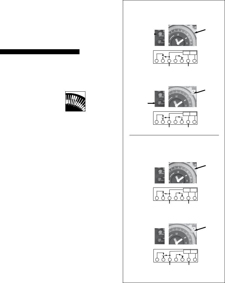
DTAV40 TRIPPERS
MODE A
In Refrigeration Mode
Arrow on timer points to current time.
|
|
Trippers are “IN” |
|
|
Indicates |
“Green” LED ON |
|
Refrigeration |
|
|
|
|
|
|
CONTROL |
TERMINATE |
|
“1 & F” Make |
|
|
|
POWER |
INPUT |
|
|
|
|
|
“2 & 4” Make |
||
“1 & 3” Break |
|
|
|
|
||
F |
3 |
1 2 |
4 N |
X |
||
|
||||||
|
|
|
L1 |
L2/N |
||
In Defrost Mode
Arrow on timer points to current time.
Trippers are “OUT”
Indicates
Defrost
“Red” LED ON
|
|
|
|
CONTROL |
TERMINATE |
|
“1 & F” Break |
|
|
|
POWER |
INPUT |
|
|
|
|
|
“2 & 4” Break |
||
“1 & 3” Make |
|
|
|
|
||
F |
3 |
1 2 |
4 N |
X |
||
|
||||||
|
|
|
L1 |
L2/N |
||
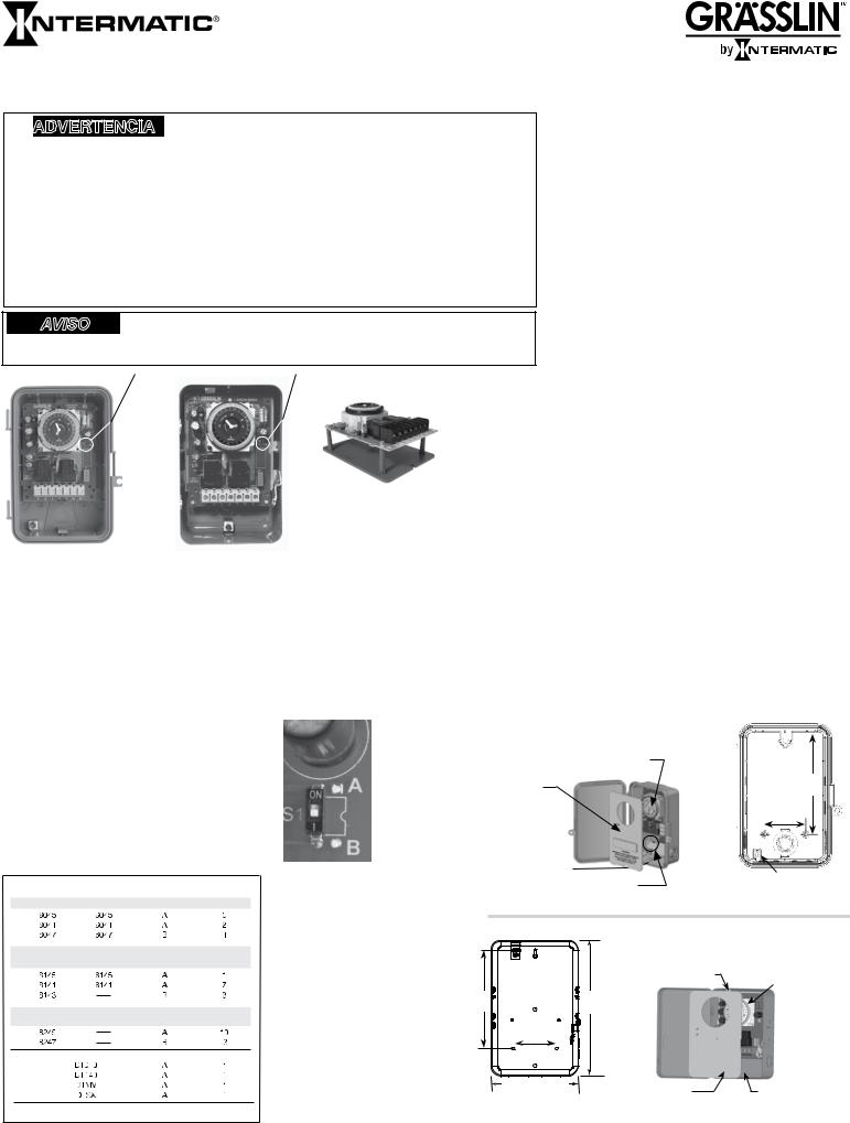
DTAV40 TRIPPERS
MODE B
In Refrigeration Mode
Arrow on timer points to current time.
Trippers are “IN” Indicates Refrigeration
Both LED’s OFF
|
|
|
|
CONTROL |
TERMINATE |
|
“1 & F” Make |
|
|
|
POWER |
INPUT |
|
|
|
|
|
“2 & 4” Break |
||
“1 & 3” Break |
|
|
|
|
||
F |
3 |
1 2 |
4 N |
X |
||
|
||||||
|
|
|
L1 |
L2/N |
||
In Defrost Mode
Arrow on timer points to current time.
Trippers are “OUT” Indicates Defrost
Both LED’s ON
|
|
|
CONTROL |
TERMINATE |
|
“1 & F” Break |
|
|
POWER |
INPUT |
|
|
|
|
“2 & 4” Make |
||
“1 & 3” Make |
|
|
|
||
3 |
1 2 |
4 N |
X |
||
F |
|||||
|
|
L1 |
L2/N |
||
Note: It is necessary to apply power across terminals 1&N in order to perform electrical test.

DTAV40 - TYPICAL WIRING DIAGRAMS
All switch positions are shown in refrigeration cycle operation, and change position upon initiation of a defrost.
8145 Replacement |
|
|
|
|
|
8041 Replacement |
|
|
|
|
|
8247 Replacement–Double Pole Switching |
|
|
|||||||||
1Mode A - No Label Required |
|
|
|
2Mode A with 8041 Terminal Block Label Applied |
3Mode B with 8247 Terminal Block Label Applied |
|
|||||||||||||||||
|
|
|
|
|
CONTROL |
TERMINATE |
|
|
|
|
|
CONTROL |
TERMINATE |
|
|
|
|
|
|
|
|
|
|
|
|
|
|
|
POWER |
INPUT |
|
|
|
|
|
POWER |
INPUT |
|
|
|
|
|
|
|
|
|
|
F |
3 |
1 |
2 |
4 |
N |
X |
N |
|
1 |
3 |
2 |
4 |
X |
LABEL |
|
N |
1 |
3 |
2 |
4 |
Xp |
p |
LABEL |
|
|
|
|
|
|
|
|
|
|
|
|
|
|
8041 |
|
|
|
|
|
|
|
|
8247 |
L1 |
|
|
THERMOS |
T |
|
L1 |
|
|
|
|
THERMOSTAT |
|
|
L1 |
|
|
|
|
|
|
|
|
|
|
|
|
|
|
|
|
|
|
|
|
|
|
|
|
|
|
|
|
|
|
|
|
|
|
|
|
|
|
FAN |
TERMINATION |
|
LINE |
|
|
|
COMPRESSOR |
|
|
|
SOLENOID |
|
|
|
|
|
|
|
|
|
|
COMPRESSOR |
|
THERMOSTAT |
FAN |
|
|
|
OR |
|
|
LINE |
|
|
|
|
|
|
|
|||
|
|
|
OR |
|
MOTOR |
W/FAN DELAY |
|
DEFROST |
|
SOLENOID VALVE |
|
|
VALVE |
|
DEFROST |
|
|
|
|
|
|||
LINE |
|
DEFROST |
SOLENOID VALVE |
|
|
|
|
|
OR |
|
|
OR |
|
|
|
|
|
|
|||||
|
OR |
|
|
|
|
|
|
CONTACTOR COIL |
|
|
|
HEATER |
|
|
PRESSURE |
|
|||||||
|
|
HEATER |
CONTACTOR COIL |
|
|
|
|
|
|
HEATER |
|
|
|
|
|
CONTACTOR |
|
|
|
|
|||
L2 |
|
|
|
|
|
|
L2 |
|
|
|
|
|
|
|
L2 |
|
|
|
|
|
SWITCH |
|
|
|
|
|
|
|
|
|
|
|
|
|
|
|
|
|
|
|
|
|
|
|
|||
DEFAULT (Out of the Box)
|
|
8047 Replacement–Double Pole Switching |
|
8045 Replacement |
|
|
|
|
|
|
|
120V Fan & Defrost Heater; 240V Compressor |
|||||||||||||||||||
4Mode B with 8047 Terminal Block Label Applied |
5Mode A with 8045 Terminal Block Label Applied |
|
|
6Mode A - No Label Required |
|
|
|||||||||||||||||||||||||
|
|
|
|
|
|
|
|
CONTROL |
TERMINATE |
|
|
|
|
|
|
CONTROL |
TERMINATE |
|
|
|
|
|
|
|
|
|
|
|
CONTROL |
TERMINATE |
|
|
|
|
|
|
|
|
|
POWER |
INPUT |
|
|
|
|
|
|
|
|
|
|
|
|
|
|
|
|
|
POWER |
INPUT |
|||
|
|
|
|
|
|
|
|
|
|
|
|
|
|
POWER |
INPUT |
|
|
|
|
|
|
|
|
|
|
|
|||||
|
|
|
|
|
|
|
|
|
|
|
|
|
|
|
|
|
|
|
|
|
|
|
|
|
|
|
|
|
|
||
|
|
N |
|
1 |
3 |
|
4 |
2 |
2 |
LABEL |
|
|
3 |
|
2 |
|
|
|
8045 |
|
|
F |
|
3 |
1 |
2 |
|
4 |
N |
X |
|
|
|
|
|
8047 |
|
F |
1-N |
4 |
X |
|
|
|
|
|
|
|
|
|
|
|
|
|
|
||||||||
L1 |
|
|
|
|
L1 |
|
LABEL |
|
|
|
|
|
|
|
|
|
|
|
|
||||||||||||
|
|
|
|
|
|
|
|
|
|
|
|
|
|
|
|
|
L1 |
|
|
|
|
|
|
|
THERMOSTAT |
|
|||||
|
|
|
|
|
|
|
|
|
|
|
|
|
|
|
|
|
|
|
|
|
|
|
|
|
|
|
|
||||
|
|
|
|
|
|
|
|
|
|
|
|
|
|
|
THERMOSTAT |
|
|
|
|
|
120V |
FAN |
DEFROST |
|
|
|
|
TERMINATION |
|||
|
SOLENOID |
|
|
|
|
|
|
|
|
|
|
|
|
|
|
FAN |
|
|
|
|
|
HEATER |
|
|
|
|
THERMOSTAT |
||||
LINE |
|
VALVE |
|
DEFROST |
|
|
|
|
|
|
|
|
COMPRESSOR |
MOTOR |
|
240V |
|
|
|
|
|
|
|
|
|
W/FAN |
|||||
|
OR |
|
|
|
|
|
|
LINE |
DEFROST |
OR |
|
|
|
|
|
|
|
|
|
|
|
|
DELAY |
||||||||
CONTACTOR |
|
HEATER |
|
|
|
|
|
SOLENOID VALVE |
|
|
|
|
|
|
|
|
|
|
|
|
|||||||||||
|
|
|
|
|
|
|
|
|
|
HEATER |
OR |
|
|
|
|
|
N |
|
|
|
|
|
|
|
|
|
|||||
L2 |
|
|
|
|
|
|
|
|
|
|
|
|
|
|
CONTACTOR COIL |
|
|
L2 |
|
|
|
|
|
|
|
|
|
|
|||
|
|
|
|
|
|
|
|
|
|
|
|
|
|
|
|
|
|
|
|
|
|
|
OR |
|
|
|
|
||||
|
|
|
|
|
|
|
|
|
|
L2 |
|
|
|
|
|
|
|
|
|
|
|
|
|
|
|
|
|
|
|||
|
|
|
|
|
|
|
|
|
|
|
|
|
|
|
|
|
|
|
|
|
|
|
|
COMPRESSOR |
|
|
|
|
|||
|
|
|
|
|
|
|
|
|
|
|
|
|
|
|
|
|
|
|
|
|
|
|
|
|
SOLENOID VALVE |
|
|
|
|
||
|
|
|
|
|
|
|
|
|
|
|
|
|
|
|
|
|
|
|
|
|
|
|
|
|
|
|
OR |
|
|
|
|
|
|
|
|
|
|
|
|
|
|
|
|
|
|
|
|
|
|
|
|
|
|
|
|
|
|
CONTACTOR COIL |
|
|
|
|
|
|
8141 Replacement |
|
|
|
|
|
|
8143 Replacement |
|
|
|
|
|
|
8143 Replacement–Double Pole Switching |
||||||||||||||||
7Mode A with 8141 Terminal Block Label Applied |
8Mode B with 8143 Terminal Block Label Applied |
|
9Mode B with 8143 Terminal Block Label Applied |
||||||||||||||||||||||||||||
|
|
|
|
|
|
|
|
CONTROL |
TERMINATE |
|
|
|
|
|
|
CONTROL TERMINATE |
|
|
|
|
|
|
|
|
|
|
|
CONTROL |
TERMINATE |
||
|
|
|
|
|
|
|
|
POWER |
INPUT |
|
|
|
|
|
|
|
POWER |
INPUT |
|
|
|
|
|
|
|
|
|
|
|
POWER |
INPUT |
N |
|
1 |
|
3 |
|
2 |
4 |
X |
|
LABEL |
|
1 |
N |
3 |
4 |
2 |
X |
|
LABEL |
|
|
1 |
N |
|
3 |
4 |
|
2 |
X |
LABEL |
|
|
|
|
|
|
|
|
|
|
|
8141 |
|
|
|
|
|
|
|
|
8143 |
|
|
|
|
|
|
|
|
|
|
|
8143 |
L1 |
|
|
|
|
|
|
THERMOSTAT |
|
|
L1 |
|
|
|
|
|
|
|
L1 |
|
|
|
|
|
|
|
|
|
|
|
|
|
|
|
|
|
|
|
|
|
|
TERMINATION |
|
|
|
|
|
|
|
|
|
|
|
|
|
|
|
|
|
|
|
|||
|
|
LINE |
|
|
|
|
COMPRESSOR |
|
LINE |
|
HOT |
|
|
|
|
|
TERMINATION |
|
|
SOLENOID |
|
|
|
|
|
|
|
|
|||
FAN |
|
DEFROST |
|
|
OR |
|
|
THERMOSTAT |
FAN |
|
CONNECT ACROSS |
|
THERMOSTAT |
LINE |
|
DEFROST |
|
|
|
|
|
||||||||||
|
|
|
OR |
|
|
W/FAN DELAY |
GAS |
|
|
W/FAN DELAY |
OR |
|
|
|
|
|
|
||||||||||||||
|
|
|
|
|
SOLENOID VALVE |
|
|
|
VALVE |
|
COMPRESSOR |
|
|
VALVE |
|
|
|
|
|
|
|
|
|||||||||
|
|
|
HEATER |
|
|
CONTACTOR COIL |
|
|
|
|
|
|
CONTACTOR |
|
HEATER |
|
|
|
|
TERMINATION |
|||||||||||
L2 |
|
|
|
|
|
|
|
|
|
|
L2 |
|
|
|
THERMOSTAT |
|
L2 |
|
|
|
|
|
|
|
|
|
|
|
THERMOSTAT |
||
|
|
|
|
|
|
|
|
|
|
|
|
|
|
|
|
|
|
|
|
|
|
|
|
|
|
|
|
|
|||
|
|
8245 Replacement |
|
|
|
|
|
|
|
|
|
|
|
WIRING LEGENDS |
|
|
|
|
|
|
|
|
|
||||||||
|
|
|
|
|
|
|
|
Paragon |
Precision |
GRASSLIN |
S1 Mode |
Terminal |
Typical |
|
|
|
Terminal Layout |
|
|
||||||||||||
10Mode A with 8245 Terminal Block Label Applied |
|
|
Ident. |
Wiring |
|
|
|
|
|
||||||||||||||||||||||
|
|
|
|
|
|
|
|
|
|
|
|
|
Model |
Model |
Model |
Selector |
Label |
Diagram |
|
|
|
|
|
|
|
|
|||||
|
|
|
|
|
|
|
|
CONTROL TERMINATE |
|
|
TIME INITIATED, TIME TERMINATED |
|
|
|
|
|
|
|
|
|
|
|
|
|
|
||||||
|
|
|
|
|
|
|
|
POWER |
INPUT |
|
|
8045 |
|
6045 |
DTAV40 |
A |
8045 |
|
|
5 |
|
|
|
|
|
|
|
|
|
||
|
|
|
|
|
|
|
|
|
|
|
|
|
|
|
|
|
F |
3 |
1-N |
2 |
4 |
X |
|
|
|||||||
|
|
|
|
|
|
|
|
|
|
|
|
|
|
|
|
|
|
|
|
|
|
|
|
|
|||||||
F |
3 |
1-N |
|
2 |
4 |
Xp |
p LABEL8245 |
|
|
8041 |
|
6041 |
DTAV40 |
A |
8041 |
|
|
2 |
|
N |
1 |
3 |
2 |
4 |
X |
|
|
||||
|
|
|
8047 |
|
6047 |
DTAV40 |
B |
8047 |
|
|
4 |
|
N |
1 |
3 |
4 |
2 |
2 |
|
|
|||||||||||
L1 |
|
|
|
|
|
|
|
|
|
|
|
|
TIME INITIATED, REMOTE TEMPERATURE OR PRESSURE TERMINATED |
F |
3 |
1 |
2 |
4 |
N |
X |
|
||||||||||
|
|
|
|
|
|
THERMOSTAT |
FAN |
|
PRESSURE |
|
|
8145 |
|
6145 |
DTAV40 |
A |
None |
1, 6 |
|
|
|||||||||||
|
|
|
|
|
|
|
|
|
|
|
|
|
|
|
|
|
|
|
|
|
|
|
|
|
|
|
|||||
LINE |
|
DEFROST |
COMPRESSOR |
MOTOR |
|
SWITCH |
|
|
8141 |
|
6141 |
DTAV40 |
A |
8141 |
|
|
7 |
|
N |
1 |
3 |
2 |
4 |
X |
|
|
|||||
|
SOLENOID VALVE |
|
|
|
|
|
|
|
|
|
|
|
|||||||||||||||||||
|
|
|
|
HEATER |
|
OR |
|
|
|
|
|
|
|
|
|
|
|
|
|
|
|
|
|
|
|
|
|
|
|
|
|
|
|
|
|
|
OR |
|
|
|
|
|
|
|
|
|
|
|
|
|
|
|
|
|
|
|
|
|
|
|
|
||
L2 |
|
|
|
|
|
CONTACTOR COIL |
|
|
|
|
|
|
|
|
|
|
|
|
8, 9 |
|
1 |
N |
3 |
4 |
2 |
X |
|
|
|||
|
|
|
|
|
|
|
|
|
|
|
|
8143 |
|
--- |
DTAV40 |
B |
8143 |
|
|
|
|||||||||||
|
|
|
|
|
|
|
|
|
|
|
|
|
|
|
|
|
|||||||||||||||
|
|
|
|
|
|
|
|
|
|
|
|
|
TIME INITIATED, PRESSURE TERMINATED |
|
|
|
|
|
|
|
|
|
|
|
|
|
|||||
|
|
|
|
|
|
|
|
|
|
|
|
|
(Separate Pressure Switch Required - see instructions) |
|
10 |
|
F |
3 |
1-N |
2 |
4 |
Xp |
p |
|
|||||||
|
|
|
|
|
|
|
|
|
|
|
|
|
8245 |
|
--- |
DTAV40 |
A |
8245 |
|
|
|
|
|
|
|
|
|
|
|
|
|
|
|
|
|
|
|
|
|
|
|
|
|
|
8247 |
|
--- |
DTAV40 |
B |
8247 |
|
|
3 |
|
N |
1 |
3 |
2 |
4 |
Xp |
p |
|
|
REPLACING EXISTING DEFROST TIMERS
The DTAV40 will replace all models of Paragon 8040, 8140,8240 Series or Precision 6040, 6140 Series and all prior Grasslin Defrost Timer models. TERMINAL IDENTIFICATION:
The standard DTAV40 terminal identification is identical to the Paragon 8145 with the addition of the “F” terminal. Terminal identification labels are provided for the other models to be placed
over the printed numbers on the printed circuit board. From the table above, select the proper label, apply to printed circuit board and wire per the original wiring or the wiring diagrams indicated.
“F” TERMINAL:
The DTAV40 contains a normally closed contact between terminals 1 and F. This terminal may be used to switch the fans off during a defrost rather than terminals 2 and 4. For hot gas defrost
applications, with the mode switch set to position “B”, the fans may be connected to terminal “F”.
8143 Replacement: When replacing a Paragon 8143, wire the termination thermostat to terminal X of the DTAV40 (with the 8143 label attached), and the adjacent blank terminal. The Paragon timers are wired to terminal X and the blank terminal. If the termination thermostat is wired to terminal N of the DTAV40 temperature termination will not occur and may result in burnout of the
DTAV40. See wiring diagrams 8 & 9.
8240 SERIES REPLACEMENT: The DTAV40 may be used to replace the Paragon 8240 series defrost timers with integral pressure termination by the addition of a remote pressure switch wired to terminals Xp and p of the DTAV40 (with an 8240 series terminal label applied). There must be no external voltage connected to the pressure switch. Set pressure switch cut-in to the same value as set on the Paragon defrost timer being replaced. Set cut-out 6 to 14 psi below cut-in. See wiring diagrams 10 and 3.
Instrucciones de instalación y operación
Temporizadores de descongelación de 40 A y voltaje automático, iniciados por hora y finalizados por temperatura, hora o presión de la serie DTAV40
ADVERTENCIA Riesgo de incendio o descarga eléctrica
•Desconecte la energía en los disyuntores o desconecte los interruptores antes de comenzar la instalación o el mantenimiento. No use la posición apagada del temporizador para el mantenimiento del equipo.
•Es posible que sea necesario usar más de un disyuntor o desconectar más de un interruptor para desenergizar el equipo antes de realizar el mantenimiento.
•Use SOLO conductores de COBRE.
•Para cargas de 40 amperios, use cable AWG n.º 8, clasificado con un mínimo de 90 ºC.
•Cablee según los requisitos de los códigos eléctricos locales y nacionales.
•Esta caja tipo 3R no proporciona una conexión a tierra entre las conexiones de los conductos. Cuando se usan conductos metálicos, también se deben instalar casquillos de conexión a tierra y cable de acoplamiento, según los requisitos de Código Eléctrico Nacional (NEC, por sus siglas en inglés).
•Al reemplazar un temporizador con un soporte de metal, reemplace el soporte por uno no metálico (se recomienda el modelo DT-B de Intermatic).
•Se deben usar ejes de conducto pluvífugos o para ubicaciones húmedas que cumplan los requisitos de la norma UL514B (estándar para piezas para conductos y cajas de distribución) en ubicaciones al aire libre.
AVISO |
Riesgo de daños al temporizador |
•Gire el disco del temporizador sólo en la dirección de las agujas del reloj.
•No mueva las agujas del reloj del temporizador. Hacerlo puede dañar el temporizador.
ESPECIFICACIONES:
Clasificación máxima de contacto de interruptor:
Resistivo de 40 amperios de 120 a 240 V CA 2HP a 240 V CA; 1 HP a 120 V CA
CONEXIONES DE CABLEADO:
Terminales del cárter de tornillo, A un cable AWG n˚8
CLASIFICACIONES AMBIENTALES:
Rango de temperatura de funcionamiento: -40˚C hasta 40˚C (-40˚F hasta 104˚F) Humedad de funcionamiento: 0 a 95% HR, no condensante
VIDA ELÉCTRICA:
50.000 Operaciones a carga completa
DIMENSIONES:
22,3 x 16,8 x 7,4 cm (8,795 x 6,631 x 2,935 pulg.) (Altura x Ancho x Profundidad)
PESO DE EMBARQUE: 1,36 kg (3 libras)
APROBACIONES DE AGENCIAS: INCLUIDA EN LISTA DE UL
Interruptor de selección de modo (S1) 
MONTAJE DE SOPORTE (elemento comercializable DT-B)
CONSULTE EL AVISO DE
REEMPLAZO DE SOPORTE Separado EN EL EMPAQUE
CAJA TIPO 3R UL |
CAJA TIPO 1 UL |
Ajuste de la selección de modo (consulte Interruptor PLD S1, la tabla y las instrucciones a continuación).
SELECCIÓN DE MODO (INTERRUPTOR PLD S1):
Primero determine cuál modelo será reemplazado (Grasslin o sus competidores). El interruptor PLD de selección de modo (que se encuentra en el lado inferior derecho de la placa) determina la configuración de los terminales 2 y 4. En la posición “A”, los terminales normalmente están cerrados y se abren durante la descongelación. En
la posición “B” los terminales 2 y 4 normalmente están abiertos y se cierran durante la descongelación. Seleccione la posición adecuada de la tabla que se encuentra a continuación y los diagramas de cableado que se indican. Para seleccionar un modo, simplemente deslice el interruptor del siguiente modo:
Modo A - posición del interruptor hacia arriba; Modo B - posición del interruptor hacia abajo;
INSTALACIÓN
1.Abra la puerta y retire la cubierta interior de protección liberando el pestillo de resorte del fondo (Figura 1). La cubierta se saca fácilmente en la caja metálica tipo 1 (Figura 4).
2.Aplique la identificación de terminal y etiquetas de puerta correspondiente. Consulte las instrucciones del kit de conversión.
3.Retire el mecanismo temporizador liberando el pestillo del circuito del fondo (Figura 1). El mecanismo temporizador viene separado en la caja metálica tipo 1 (Figura 4).
4.Seleccione los orificios ciegos que desee usar. Inserte un destornillador en la ranura para retirar el orificio ciego interior de 1/2 pulg. y presione cuidadosamente para soltar el orificio ciego. Retire la tapa. Si se necesita un orificio ciego de 3/4 pulg., retire el anillo exterior con un alicate luego de retirar el orificio ciego de 1/2 pulg. Alise los bordes con un cuchillo si fuera necesario, solo en la caja de plástico.
5.Coloque la caja en la ubicación de montaje que desee y marque los tres orificios de montaje (consulte la Figura 2, para obtener más información sobre el tipo 3R y la Figura 3, para obtener más
información sobre el tipo 1 que se muestra a continuación). Primero instale el tornillo superior en la superficie de montaje y la caja colgante en la cabeza del tornillo a través del ojo de la cerradura; luego atornille los dos tornillos restantes en los orificios del fondo.
6.Conexión a tierra: Termine todos los cables a tierra en el terminal de tierra en la parte inferior de la caja.
7.Vuelva a instalar el temporizador en la caja.
8.Reemplace la cubierta interior de protección.
Nota: Cuando esté seleccionado el modo “B” DTAV40 funcionará del siguiente modo:
Modo de refrigeración - Las luces LED ROJOS y VERDES se APAGARÁN (1 y 3, y 2 y 4 se desconectan, mientras 1 y F se conectan)
Modo de descongelación - Los LED ROJOS Y VERDES se ENCIENDEN (1 y 3, y 2 y 4 se conectan, mientras 1 y F se desconectan)
Paragon |
Precision |
Selección |
Diagrama |
de modo |
de cableado |
FINALIZADO POR HORA
INICIADO POR HORA, SEÑAL REMOTA DE FINALIZACIÓN
POR TEMPERATURA O PRESIÓN
INICIADO POR HORA, FINALIZADO POR PRESIÓN
[Se necesita un presostato separado (consulte las instrucciones)]
Grasslin
Referencia
DTAV40 Substituye sobre 40 modelos
Mecanismo temporizador
Cubierta interior de protección
Pestillo de resorte
Pestillo del circuito impreso (PCB)
Caja tipo 3R
Figura 1
15,56 cm (6-1/8 pulg.)
6,35 cm (2-1/2 pulg.)
Terminal de tierra
Caja tipo 3R
Figura 2
|
Pestillo del circuito |
Mecanismo temporizador |
|
impreso (PCB) |
|
|
|
|
10,32 cm |
19,69 cm |
|
(4-1/16 pulg.) |
(77-3/4¾" pulg.) |
|
6,35 cm |
|
|
(2-1/2 pulg.) |
|
|
12,7 cm (5 pulg.) |
Cubierta |
Caja tipo 1 |
5" |
||
Caja tipo 1 |
interior de |
Figura 4 |
Figura 3 |
protección |
 Loading...