


H55

USER'S MANUAL
Of
Intel H55 Express Chipset
Based
M/B for Intel LGA 1156 Processors
NO. G03-HI06-F
Rev: 2.0
Release date: December, 2010
Trademark:
* Specifications and Information contained in this docume ntation ar e furnishe d for inf ormation use only , and ar e
subject to change at any time without notice, and should not be construed as a commitment by manufacturer.

Environmental Protection Announcement
Do not dispose this electronic device into the trash while discarding. To minimize pollution
and ensure environment protection of mother earth, please recycle.
i

TABLE OF CONTENT
ENVIROMENTAL SAFETY INSTRUCTION................................................................iii
USER’S NOTICE.........................................................................................................iv
MANUAL REVISION INFORMATION.........................................................................iv
ITEM CHECK LIST......................................................................................................iv
COOLING SOLUTIONS ..............................................................................................iv
CHAPTER 1
1-1 FEATURES OF MOTHERBOARD .............................................................................1
1-1.1 SPECIAL FEATURES OF MOTHERBOARD...............................................2
1-2 SPECIFICATION.........................................................................................................4
1-3 PERFORMANCE LIST................................................................................................5
1-4 LAYOUT DIAGRAM....................................................................................................6
INTRODUCTION OF H55 EXPRESS CHIPSET MOTHERBOARDS
CHAPTER 2 HARDWARE INSTALLATION
2-1 HARDWARE INSTALLATION STEPS.......................................................................8
2-2 CHECKING MOTHERBOARD'S JUMPER SETTING................................................8
2-3 INSTALLING CPU.......................................................................................................10
2-3-1 GLOSSARY...................................................................................................10
2-3-2
2-3-3 LGA 1156 CPU INSTALLATION GUIDE......................................................11
2-3-4 INTEL REFERENCE THERMAL SOLUTION ASSEMBLY..........................12
2-4 INSTALL MEMORY ....................................................................................................13
2-5 EXPANSION CARDS..................................................................................................14
2-5-1 PROCEDURE FOR EXPANSION CARD INSTALLATION..........................14
2-5-2 ASSIGNING IRQ FOR EXPANSION CARD.................................................14
2-5-3 PCI-EXPRESS SLOT.....................................................................................15
2-5-4 INSTALLING THE CROSSFIRE/SLI BRIDGE CARD ..................................16
2-6 CONNECTORS, HEADERS........................................................................................17
2-6-1 CONNECTORS .............................................................................................17
2-6-2 HEADERS .....................................................................................................20
2-7 STARTING UP YOUR COMPUTER ...........................................................................23
CHAPTER 3 INTRODUCING BIOS
3-1 ENTERING SETUP.....................................................................................................24
3-2 GETTING HELP ..........................................................................................................24
3-3 THE MAIN MENU........................................................................................................25
3-4 STANDARD BIOS FEATURES ..................................................................................26
3-5 ADVANCED BIOS FEATURES..................................................................................27
3-5-1 CPU FEATURES ...........................................................................................28
3-6 ADVANCED CHIPSET FEATURES...........................................................................29
3-7 INTEGRATED PERIPHERALS...................................................................................30
3-8 POWER MANAGEMENT SETUP...............................................................................31
3-9 MISCELLANEOUS CONTROL...................................................................................32
3-10 PC HEALTH STATUS.................................................................................................32
3-10-1 SMART FAN CONFIGURATION...............................................................33
3-11 USER OVERCLOCK SETTINGS................................................................................33
3-12 PASSWORD SETTINGS.............................................................................................35
3-13 LOAD OPTIMAL DEFAULTS/LOAD STANDARD DEFAULTS................................35
3-14 SAVE CHANGES AND EXIT/ DISCARD CHANGES AND EXIT................................36
CHAPTER 4 DRIVER & FREE PROGRAM INSTALLATION
MAGIC INSTALL SUPPORTS WINDOWS XP/VISTA/7.....................................................37
4-1 INF INSTALL INTELH55 CHIPSET SYSTEM DRIVER ..................................38
4-2 SOUND INSTALL ALC HD AUDIO CODEC DRIVER............................................39
4-3 REALTEK INSTALL REALTEK GIGABIT ETHERNET NIC DRIVER...............40
4-4 NORTON INSTALL NORTON INTERNET SECURITY 2010..................................41
4-5 PC-HEALTH INSTALL MYGUARD HARDWARE MONITOR UTILITY..................41
4-6 VGA INSTALL INTEL HD VGA DRIVER............................................................42
4-7 DOTNET INSTALL DOTNET....................................................................................43
4-8 IMSS INSTALL IMSS ..........................................................................................43
4-9 AHCI/RAID INSTALL INTEL AHCI /RAID DRIVER...............................................44
4-10 HOW TO UPDATE BIOS ............................................................................................45
4-11 PRO MAGIC PLUS FUNCTION INTRODUCTION.....................................................45
4-12 G.P.I.FUNCTION LED DISPLAY................................................................................47
ABOUT INTEL LGA 1156 CPU SOCKET.................................................10
ii

Environmental Safety Instruction
z Avoid the dusty, humidity and temperature extremes. Do not place the product in
any area where it may become wet.
z 0 to 40 centigrade is the suitable temperature. (The figure comes from the request
of the main chipset)
z Generally speaking, dramatic changes in temperature may lead to contact
malfunction and crackles due to constant thermal expansion and contraction from
the welding spots’ that connect components and PCB. Computer should go
through an adaptive phase before it boots when it is moved from a cold
environment to a warmer one to avoid condensation phenomenon. These water
drops attached on PCB or the surface of the components can bring about
phenomena as minor as computer instability resulted from corrosion and oxidation
from components and PCB or as major as short circuit that can burn the
components. Suggest starting the computer until the temperature goes up.
z The increasing temperature of the capacitor may decrease the life of computer.
Using the close case may decrease the life of other device because the higher
temperature in the inner of the case.
z Attention to the heat sink when you over-clocking. The higher temperature may
decrease the life of the device and burned the capacitor.
iii

USER’S NOTICE
COPYRIGHT OF THIS MANUAL BELONGS TO THE MANUFACTURER. NO PART OF THIS
MANUAL, INCLUDING THE PRODUCTS AND SOFTWARES DESCRIBED IN IT MAY BE
REPRODUCED, TRANSMITTED OR TRANSLATED INTO ANY LANGUAGE IN ANY FORM OR BY
ANY MEANS WITHOUT WRITTEN PERMISSION OF THE MANUFACTURER.
THIS MANUAL CONTAINS ALL INFORMATION REQUIRED FOR THE UTILIZATION OF THESE
MOTHER-BOARDS TO MEET THE USE R’S REQUIREMENTS. B UT IT WIL L CHANGE, CORRECT
AT ANY TIME WITHOUT NOTICE. MANUFACTURER PROVIDES THIS MANUAL “AS IS”
WITHOUT WARRANTY OF ANY KIND, AND WILL NOT BE LIABLE FOR ANY INDIRECT, SPECIAL,
INCIDENTIAL OR CONSEQUENTIAL DAMAGES (INCLUDING DAMANGES FOR LOSS OF
PROFIT, LOSS OF BUSINESS, LOSS OF USE OF DATA, INTERRUPTION OF BUSINESS AND
THE LIKE).
PRODUCTS AND CORPORATE NAMES APPEARING IN THIS MANUAL MAY OR MAY NOT BE
REGISTERED TRADEMARKS OR COPYRIGHTS OF THEIR RESPECTIVE COMPANIES, AND
THEY ARE USED ONLY FOR IDENTIFICATION OR EXPLANATION AND TO THE OWNER’S
BENEFIT, WITHOUT INTENT TO INFRINGE.
Manual Revision Information
Reversion Revision History Date
2.0 Second Edition December, 2010
Item Checklist
5
In t e l H 5 5 E x p r e s s c h i p s e t b a s e d m otherboard
5
User’s manual
5
DVD for motherboard utilities
5
SATA Cable
5
I/O Back Panel Shield
Intel Core Processor Family
Cooling Solutions
As processor technology pushes to faster speeds and higher performance, thermal
management becomes increasingly crucial while building computer systems.
Maintaining the proper thermal environment is the key to reliable, long-term system
operation. The overall goal in providing the proper thermal environment is keeping the
processor below its specified maximum case temperature. Heat sinks induce
improved processor heat dissipation through increased surface area and
concentrated airflow from attached fans. In addition, interface materials allow effective
transfers of heat from the processor to the heat sink. For optimum heat transfer, Intel
recommends the use of thermal grease and mounting clips to attach the heat sink to
the processor.
When selecting a thermal solution for your system, please refer to the website below
for collection of heat sinks evaluated and recommended by Intel for use with Intel
processors. Note, those heat sinks are recommended for maintaining the specified
Maximum T case requirement. In addition, this collection is not intended to be a
comprehensive listing of all heat sinks that support Intel processors.
iv

Chapter 1
Introduction of H55 Express Chipset Motherboards
1-1 Features of Motherboard
The H55 Express chipset based motherboard series are based on Intel H55 Express
chipset technology which supports the innovative Intel LGA 1156 socket Intel®
Core™ i7 Quad Processor、Intel® Core™ i5 Quad Processor、Intel® Core™ i3 Dual
Processor and Intel® Pentium Processor.
The H55 Express chipset based motherboard series deliver the revolutionary levels of
performance enabling vivid, high-definition experiences and multi-tasking
responsiveness from state-of-the-art Intel quad-core technologies, AMD CrossFire
technology through the high bandwidth of 4 dual-channel DDRIII1066/DDRIII1333
MHz system memories which are expandable to 16 GB capacity and the new
generation of PCI Express interface for the latest graphics AMD cards.TheH55
Express chipset motherboard series are absolutely the ultimate solution for game
enthusiasts and applications, and it also meets the demanding usage of computing of
gaming, multimedia entertainment and business applications.
The motherboard provides six serial ATA2 interfaces of 3.0 Gb / s data transfer rate
for six serial ATA devices.
The H55 Express chipset Based motherboard provides dual Gigabit LAN function by
using Gigabit LAN chips which supports 10M / 100M / 1Gbps data transfer rate.
Embedded 8-channel HD CODEC is fully compatible with Sound Blaster Pro
®
standards that offer you with the home cinema quality and absolutely software
compatibility.
The H55 Express chipset based motherboard series offer two PCI-Express2.0 x16
graphics slots with PE2 being PCI Express 2.0 x16@16 lane slot while PE3 being PCI
Express 2.0 x16@ 4 lane slot. These two graphics slots are fully compatible with the
latest AMD CrossFireX Technology to guarantee the fully operational Multi-GPUs
graphics function and avoid the possible installation error. One PCI Express x1 I/O
slot and two 32-bit PCI slots guarantee the rich connectivity for the I/O of peripherals.
And theH55 motherboard is embedded with a mini-PCIE slot that supports WiFi card.
Embedded USB controllers as well as capability of expanding to 10 of USB2.0
functional ports delivering 480Mb/s bandwidth of rich connectivity, these
motherboards meet the future USB demands which are also equipped with hardware
monitor function on system to monitor and protect your system and maintain your
non-stop business computing.
Some special features---
/
G.P.I. Function/3D Audio/DIY Clear/Power on Button/Reset Button
CPU Smart Fan/ CPU Vcore 7-shift/ Debug Port/OC-CON
in this
motherboard is designed for power user to use the over-clocking function in more
flexible ways. But please be caution that the over-clocking may cause the failure in
system reliability. This motherboard provides the guaranteed performance and meets
1

the demands of the next generation computing. But if you insist to gain more system
performance with variety possibilities of the components you choose, please be
careful and make sure to read the detailed descriptions of these value added product
features, please get them in the coming section.
1-1.1 Special Features of motherboard
CPU Smart Fan--- The Noise Management System
It’s never been a good idea to gain the performance of your system by sacrificing its
acoustics. CPU Smart Fan Noise Management System is the answer to control the
noise level needed for now-a-day’s high performance computing system. The system
will automatically increase the fan speed when CPU operating loading is high, after
the CPU is in normal operating condition, the system will low down the fan speed for
the silent operating environment. The system can provide the much longer life cycle
for both CPU and the system fans for game use and business requirements.
CPU Vcore 7-Shift--- Shift to Higher Performance
The CPU voltage can be adjusted up by 7 stages for the precisely over-clocking of
extra demanding computing performance.
Debug Port--- The Professional Hardware Diagnosis System
Being bugged of abnormal system failure through the tossed and turned nights no
more, the embedded Hardware Debug Port offers you the real-time visual system
healthy for the demanding usage of computing. No more bugging by unknown system
failure and no more time wasted in the first moment of 24-hour nonstop ping business
computing, the embedded Debug Port will turn you into a well training hardware
professional with the seeing system situation. (The Post Code please refer Appendix)
OC-CON ---High-polymer Solid Electrolysis Aluminum Capacitors
The working temperature is from 55 degrees Centigrade below zero to 125 degrees
Centigrade, OC-CON capacitors possess superior physical characteristics that can
be while reducing the working temperature between 20 degrees Centigrade each time,
intact extension 10 times of effective product operation lives, at not rising degrees
Centigrade of working temperatures each time a relative one, life of product decline
10% only too.
G.P.I. Function—Green power indicator function
The full name of G.P.I technology is Green Power Indicator technology, obviously
technology utilized to low power consumption. G.P.I is a technology with remarkable
power saving function.
3D Audio—(3D Audio Sound Effect)
OP with two-stage Butterworth filter and quadruple noninverting amplifier enhances
bass effect under the 100MHz range to perfect audio effect, brings you stunning
shock experience in video game, true-to-life simulated feeling when watching films
and the greatest touch as that in the concert. There is a 3D Audio button integrated on
the board. Press down the button to enable 3D audio effect or press again to disabled
it.
2

DIY Clear
This CMOS Buttons (CMOS1) is to facilitate the clear COMS process for power user
overclocking function. The user can easily clear or restore COMS settings by pressing
down the button, without taking trouble to remove the case and locate the jumper for
clear CMOS. (Please remove or turn off the power supply before COMS clear)
Power on Button
You can easily start the computer by pressing down this button for a few seconds,
without troubling yourself to locate the front panel jumpers to find the Power on
jumper.
Reset Button
You can easily restart the computer by pressing down this button for a few seconds,
without troubling yourself to locate the front panel jumpers to find the reset jumper.
3

1-2 Specification
Spec Description
Design z
Chipset z
CPU Socket
Memory Sockets
Expansion Slots
Serial ATA2
Gigabit LAN
8-CH HD Audio
BIOS z
ATX form factor 4 layers PCB size: 30.5x24.5cm
Intel H55 Express Chipset
Intel LGA 1156 socket Intel® Core™ i7 Quad Processor
z
Intel® Core™ i5 Quad Processor、Intel® Core™ i3 Dual
Processor and Intel® Pentium Processor
DDRIII module sockets x 4
z
Support 4pcs DDRIII 1066MHz/ DDRIII 1333 MHz memory
z
modules expandable to 16GB.
Support Dual- channel function
z
PCI-Express2.0 x16 slot 2pcs
z
PCI-Express2.0 x1 slot 1pcs
z
32-bit PCI slot 2pcs
z
z
Mini PCI-Express
The Intel H55 chipset supports six internal Serial ATA ports
z
1pcs
for six SATA devices providing 3.0 Gb/sec data transfer
rate
Integrated PCI-E Gigabit LAN chip
z
Supports Fast Ethernet LAN function provide10Mb/100Mb/
z
1Gb /s data transfer rate
8-channel HD Audio Codec integrated
z
Support 8-channel 3D surround & Positioning Audio
z
Audio driver and utility included
z
AMI 32MB SMT Flash ROM
、
Multi I/O
PS/2 keyboard connector x1
z
PS/2 Mouse connector x1
z
HDMI connector x1
z
VGA connector x1/DV I connector x1
z
Coaxial S/PDIF Out connector x1
z
ESATA connector x1 /SATA connectors x6
z
USB2.0 port x4 and headers x3
z
RJ-45 LAN connector x1
z
Audio connector x1 (8-CH Audio)
z
Serial Port headerx1
z
HDMI-SPDIF header x1
z
IR header x 1
z
CDIN header x1
z
FP_AUDIO header x1
z
4
Ap
A
y
Q
)
1-3 Performance List
The following performance data list is the testing result of some popular benchmark
testing programs. These data are just referred by users, and there is no responsibility
for different testing data values gotten by users (the different Hardware & Software
configuration will result in different benchmark testing results.)
Test Environment
CPU I3 540 VGA DRIVER
BIOS T03 MEMORY
VGA
onboard VG
HDD WesternDigtal 160GB SATA
3DMark Vantage 4344
3D Mark 2006 1393
3D Mark 2005 2955
AQUAMRK3
System / CPU / Memor
Graph / HDD 3227
Content Creation Winstone 2004 54.5
Business Winstone 2004 33.5
Business/Hi-end Disk Winmark99 21700
Business/Hi-end Graphic Winmark
SySMark 2004: SISMark Rating(Internet Content Creation / Office Productivity )
SySMark 2004 309
3D Creation / 2D Creation 550
/ Web publication 474
Communication / Document Creation 183
/ Data Analysis 343
6159
Winbench 99 V2.0:
PCMark2005
8519
5421
683
400
acer 2G1333
5157
SiSOFT Sandra 2005 : 1.CPU Arithmetic Benchmark 2.Memory bandwidth Benchmark
3.CPU Multi-Media Benchmark
1.Dhrystone ALU MIPS 45.21
Whetstone FPU iSSE2 FLOPS
2.Int/Float Buffered iSSE2 MB/S
3.Integer/Floating-Point SSE2 IT/S
UT2003 Benchmark
uake3 DEMO1 / DEMO2 FPS
Return to Castle Wolfenstein
Super Pi (1M
CPUZ System / CPU Clock
Second 13.369s
FPS
32.02
37.88
9.26
289.2
291.6
5
189.550140
r
p
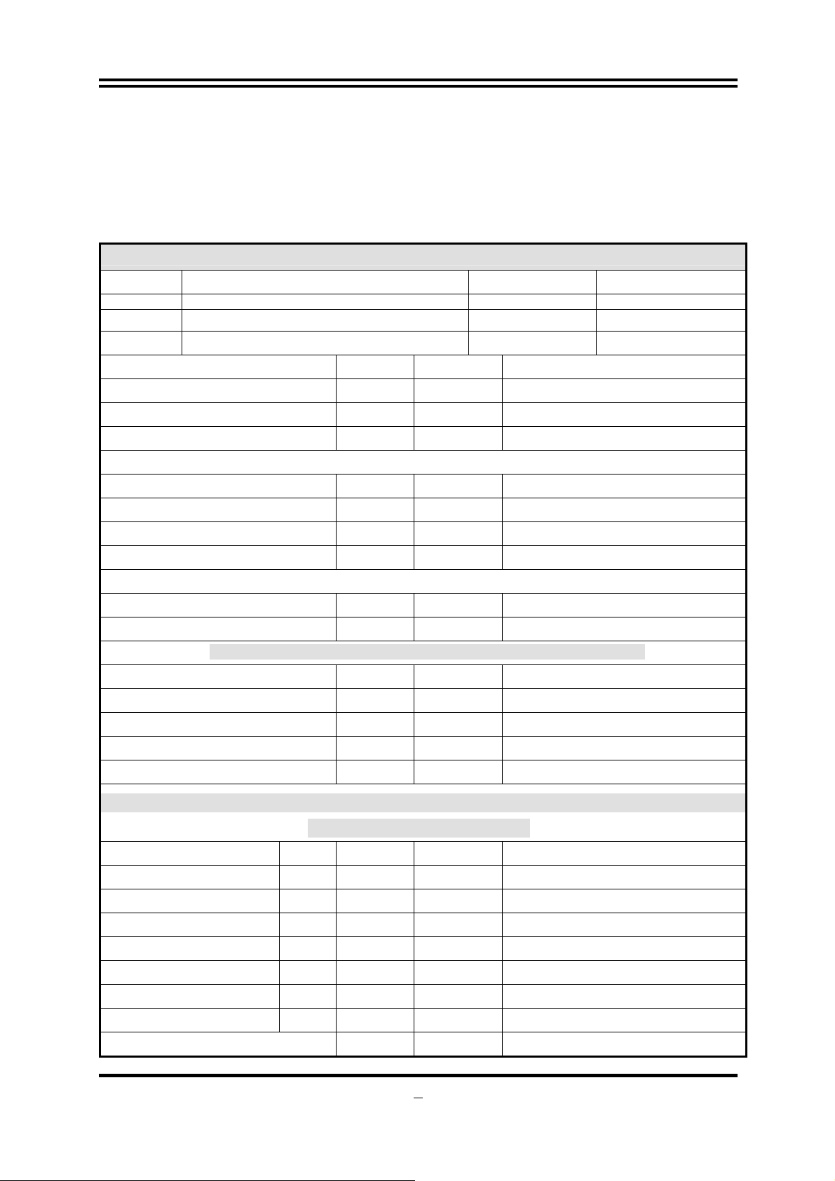
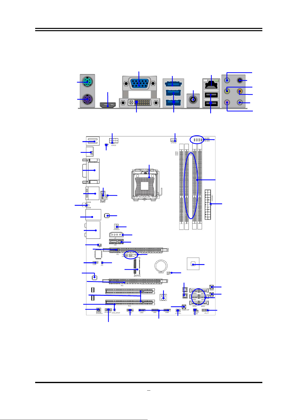
1-4 Layout Diagram
PS/2 Keyboard
PS/2 Mouse
Connector
Connector
HDMI
Connector
VGA Connector
DVI Connector
ESATA
Coaxial
SPDIF_OUT
USB Connectors
RJ-45 LAN
USB Connectors
Line-IN
RS-OUT
Line-OUT
CS-OUT
SS-OUT
MIC-IN
PS/2 KB/MS ports
HDMI Connector
VGA Connector
DVI Connector
ESATA
USB ports
Coaxial
SPDIF_OUT
Connector
RJ-45 Over
USB Connector
8 CH HD Audio
IR1 Header
PCI Express2.0 x16
By 1 6 lane
CDIN Header
Audio Decode
PCI Express2.0 x16
By 4 lane
HDMI-SPDIF
3D Audio Button
Over
ort
over
8-CH HD
PCI Slots
ATX 12V
Power Connector
JP11
E-SATA1
JP2
Gigabit LAN Chip
JP5
MINIPCI-E
COM1 Header
Front Panel Audio
CPU Socket
SYSFAN2
4-Pin PWR Connector
PCI Express2.0 x1
JP6/JP7/JP8/JP9//JP10
Debug port
USB Headers
CPUFAN1
JBAT
32MB SMT Flash ROM
SYSFAN1
Power LED Header
Speaker Header
G.P.I LED
DDR3 Socket x 4
(DIMM1~DIMM4)
ATX Power Conn.
Intel H55 Chipset
Reset Button
CMOS1 Clear Button
Serial-ATAII Connecto
(SATA 1~6)
6

Jumpers
Jumper Name Description
JBAT CMOS RAM Clear 2-pin Block
JP11 KB/MS Power On Enabled/Disabled 3-pin Block
JP2 USB Power On Enabled/Disabled 3-pin Block
JP6/JP7/JP8/JP9 PE1/MINIPCI-E select 3-pin Block
JP10 MINIPCI-E 3VSB/VCC3 select 3-pin Block
Sockets and Slots
Socket/Slot Name Description
CPU Socket LGA 1156 CPU Socket LGA 1156 CPU Socket
DIMM1~DIMM4
PCI1,PC2
PE1
PE2,PE3
DDRIII Module Sockets 240-pin DDRIII Module Sockets
PCI Slots 32-bit PCI Local Bus Expansion slots
PCI-Express2.0 x 1 Slot PCI-Express2.0 x 1 Expansion Slots
PCI-Express 2.0x 16
Slots
PCI-Express2.0 x16 Expansion Slots
Connectors
Connector Name Description
ATXPWR ATX Power Connector 24-pin Block
ATX12V ATX 12V Power Connector 8-pin Block
J1 Large 4-pin Power Connector 4-pin Block
KB1 PS/2 Keyboard/Mouse Connector 6-pin Female
VGA D-Sub Connector 15-pin Connector
DVI Digital Visual Interface 24-pin Connector
HDMI High-Definition Multimedia 19-pin Connector
USB fromUL1 and CN2 USB 2.0 Port Connectors 4-pin Connector
RJ45 LAN from UL1 RJ-45 LAN Port Over USB Connectors. 8-pin Connector
AUDIO 8-CH Audio Connector 6 phone jack
SATA~SATA6 Serial ATA2 Connector 7-pin Connector
E-SATA from CN1 External Serial ATA2 Connectors 7-pin Connector
SPDIF_ Out Coaxial S/PDIF Out Connector 1-pin Connector
Headers
Header Name Description
FP_AUDIO SPEAKER, MIC header 9-pin Block
USB2,USB3, USB4 USB Port Headers 9-pin Block
SPEAK PC Speaker header 4-pin Block
PWR LED Power LED header 3-pin Block
JW_FP(PWR
LED/Reset/
HD LED/PWR BTN)
CPUFAN1 CPUFAN Header 4-pin Block
SYSFAN1, SYSFAN2 System FAN Headers 3-pin Block
CDIN CD Audio-In Header 4-pin Block
IR1 IR Header 5-pin Block
COM1 Serial Port Header 9-pin Block
HDMI-SPDIF SPDIF-Out header 2-pin Block
Front Panel Header
(including Power LED/ IDE activity
LED/Reset switch / Power On Button lead)
9-pin Block
7
Chapter 2
Hardware Installation
WARNING!
Turn off your power when adding or removing expansion cards or
other system components. Failure to do so may cause severe
damage to both your motherboard and expansion cards.
2-1 Hardware installation Steps
Before using your computer, you had better complete the following steps:
1. Check motherboard jumper setting
2. Install CPU and Fan
3. Install System Memory (DIMM)
4. Install Expansion cards
5. Connect IDE Front Panel /Back Panel cable
6. Connect ATX Power cable
7. Power-On and Load Standard Default
8. Reboot
9. Install Operating System
10. Install Driver and Utility
2-2 Checking Motherboard’s Jumper Setting
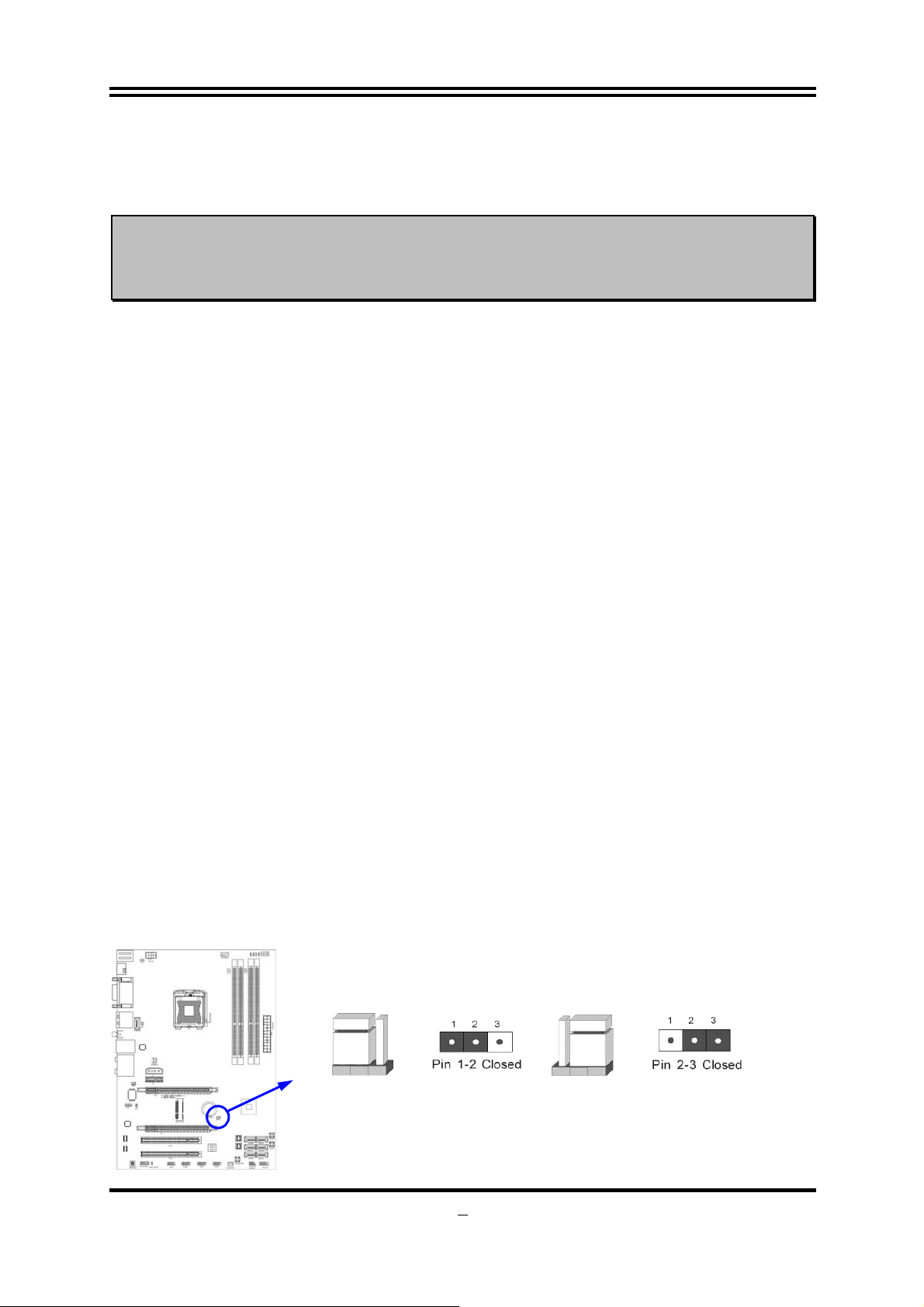
(1) CMOS RAM Clear (3-pin): JBAT
A battery must be used to retain the motherboard configuration in CMOS RAM
short 1-2 pins of JBAT to store the CMOS data.
To clear the CMOS, follow the procedure below:
1. Turn off the system and unplug the AC power
2. Remove ATX power cable from ATX power connector
3. Locate JBAT and short pins 2-3 for a few seconds
4. Return JBAT to its normal setting by shorting pins 1-2
5. Connect ATX power cable back to ATX power connector
Note: When should clear CMOS
1. Troubleshooting
2. Forget password
3. After over clocking system boot fail
JBATJBAT
1-2 Closed Normal
CMOS RAM Clear Setting
2-3 Closed Clear CMOS
8
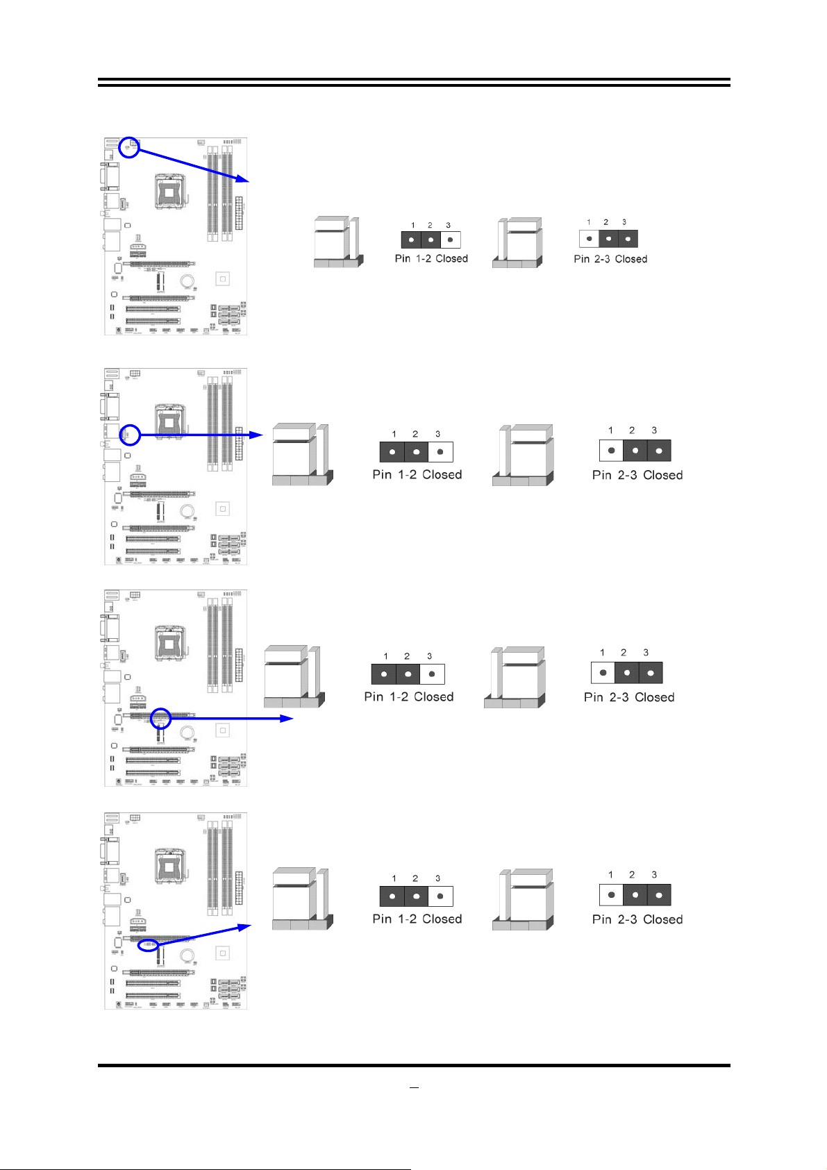
(2) KB/MS Power on Function Enabled/Disabled: JP11
JP11
1-2 Closed KB/MS Power ON Disable (Default)
Keyboard/ M ou se Power On Setting
(3) USB Power On function Enabled/Disabled: JP2
1-2 closed USB Power On Disable
(Default)
USB Power-On Setting
2-3 closed USB Power On Enabled
(4) MINIPCI-E 3VSB/VCC3 Select: JP10
JP11
2-3 Closed KB/MS Power ON Enabled
JP2 JP2
1-2 Close 3VSB
(5) PE1/MINIPCI-E Select:JP6/JP7/JP8/JP9
1-2 Close(all): PE1
9
JP10 JP10
2-3 Close VCC3
JP6/JP7/JP8/JP9 JP6/JP7/JP8/JP9
2-3 Close(all): MINIPCI-E

2-3 Installing CPU
2-3-1 Glossary
Chipset (or core logic) - two or more integrated circuits which control the interfaces
between the system processor, RAM, I/O devises, and adapter cards.
Processor slot/socket - the slot or socket used to mount the system processor on
the motherboard.
Slot (PCI-E, PCI, RAM) - the slots used to mount adapter cards and system RAM.
PCI - Peripheral Component Interconnect - a high speed interface for video cards,
sound cards, network interface cards, and modems; runs at 33MHz.
PCI Express2.0- Peripheral Component Interconnect Express2.0, developed in 2003,
the speed of each line doubled from the previous PCI-E of 2.5Gbps to 5 Gbps.
Serial Port - a low speed interface typically used for mouse and external modems.
Parallel Port - a low speed interface typically used for printers.
PS/2 - a low speed interface used for mouse and keyboards.
USB - Universal Serial Bus - a medium speed interface typically used for mouse,
keyboards, scanners, and some digital cameras.
Sound (interface) - the interface between the sound card or integrated sound
connectors and speakers, MIC, game controllers, and MIDI sound devices.
LAN (interface) - Local Area Network - the interface to your local area network.
BIOS (Basic Input/Output System) - the program logic used to boot up a computer
and establish the relationship between the various components.
Driver - software, which defines the characteristics of a device for use by another
device or other software.
Processor - the "central processing unit" (CPU); the principal integrated circuit used
for doing the "computing" in "personal computer"
Front Side Bus Frequency -
generated by the clock generator for CPU, DRAM and PCI BUS.
CPU L2 Cache -
the flash memory inside the CPU, normal it depend on CPU type.
the working frequency of the motherboard, which is
2-3-2 About Intel LGA 1156 CPU Socket
This motherboard provides an 1156-pin DIP, LGA 1156 Land Grid Array socket,
referred to as the LGA 1156 socket.
The CPU that comes with the motherboard should have a cooling FAN attached to
prevent overheating. If this is not the case, then purchase a correct cooling FAN
before you turn on your system.
NOTED!
To install a CPU, first turn off your system and remove its cover. Locate the LGA 1156
socket and open it by first pulling the level sideways away from the socket then
upward to a 135-degree angle. Insert the CPU with the correct orientation as shown
below. The notched corner should point toward the end of the level. Because the CPU
Be sure that there is sufficient air circulation across the processor’s
heat sink and CPU cooling FAN is working correctly, otherwise it
may cause the processor and motherboard overheat and damage,
you may install an auxiliary cooling FAN, if necessary.
10
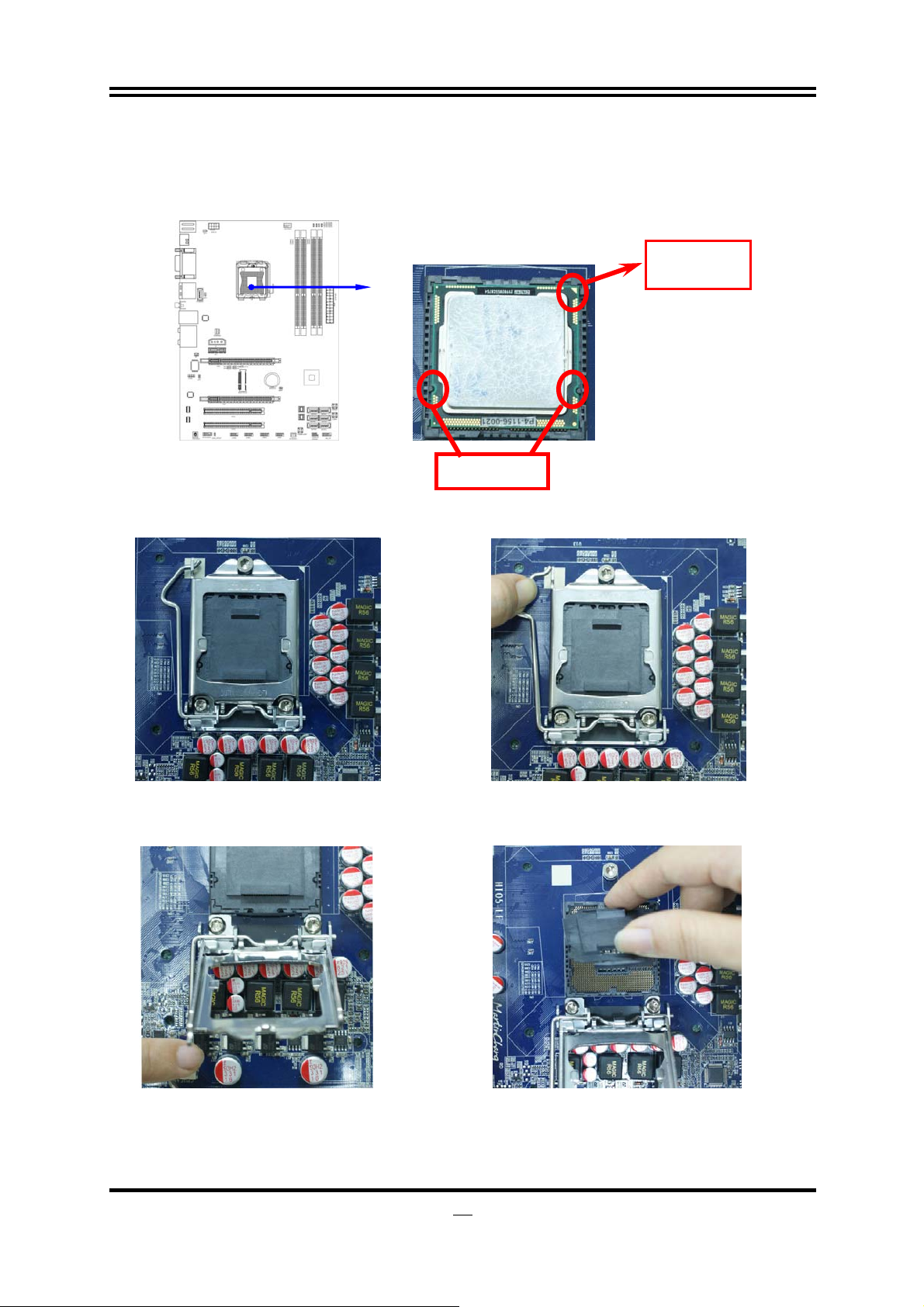
has a corner pin for two of the four corners, the CPU will only fit in the orientation as
shown.
When you install the CPU into the LGA 1156 socket, there’s no force required CPU
insertion; then press the level to locate position slightly without any extra force.
Pin-1
Indicator
Alignment key
2-3-3 LGA 1156 CPU Installation Guide
1. Please make sure that CPU socket is facing
towards you and the level is on you left hand
side.
2. Press down the level and move it to the left side
to make sure it is freed from the hook and then
open it upwards about 135 degree.
3. Open the level upwards about 135 degree and the
metal protection plate will be pulled up at the same
time.
4. Remove the plastic protective cap from the
socket. (Put it to the original place if CPU is not
installed. Do not touch the metal contact point of
the CPU socket).
11
 Loading...