


BBS2600STBR
Table of contents
 Loading...
Intel® Server Board S2600ST
Product Family
Technical Product Specification
An overview of product features, functions, architecture, and support specifications.
Rev 1.03
March 2018
Intel® Server Products and Solutions

<This page is left intentionally blank>
Intel® Server Board S2600ST Product Family Technical Product Specification
Date
Revision
Changes
June 2017
1.0
Production release.
August 2017
1.01
Added Design and Environmental Specifications Section
Corrected post codes on Appendix B (Tables: 40, 41 and 42)
Added a note on section 4.6.2
Fixed a part on section 5.3.1 where DIMM population suggested was not accurate
Added Information to Appendix E
February 2018 1.02
Document Revision History
Corrected thermal Configuration Tables on Appendix E (Tables: 49, 50, 51 and 52)
Corrected the Maximum TDP from 165W to 205W
Added section 10.5.4 Chassis Intrusion header Pin-out
Added reference to the Chassis Intrusion Header on Figure 2
March 2018 1.03
Added documents to the Reference documents table
3

Intel® Server Board S2600ST Product Family Technical Product Specification
Disclaimers
Intel technologies’ features and benefits depend on system configuration and may require enabled
hardware, software or service activation. Learn more at Intel.com, or from the OEM or retailer.
You may not use or facilitate the use of this document in connection with any infringement or other legal
analysis concerning Intel products described herein. You agree to grant Intel a non-exclusive, royalty-free
license to any patent claim thereafter drafted which includes subject matter disclosed herein.
No license (express or implied, by estoppel or otherwise) to any intellectual property rights is granted by this
document.
The products described may contain design defects or errors known as errata which may cause the product
to deviate from published specifications. Current characterized errata are available on request.
Intel disclaims all express and implied warranties, including without limitation, the implied warranties of
merchantability, fitness for a particular purpose, and non-infringement, as well as any warranty arising from
course of performance, course of dealing, or usage in trade.
Intel, the Intel logo, Xeon, and Xeon Phi are trademarks of Intel Corporation in the U.S. and/or other
countries.
*Other names and brands may be claimed as the property of others.
© Intel Corporation. All Rights Reserved.
4

Intel® Server Board S2600ST Product Family Technical Product Specification
Table of Contents
1. Introduction ............................................................................................................................................................... 13
1.1 Chapter Outline ............................................................................................................................................................... 14
1.2 Intel® Server Board Use Disclaimer......................................................................................................................... 14
2. Server Board Family Overview .............................................................................................................................. 15
2.1 Server Board Feature Set ............................................................................................................................................ 16
2.2 Server Board Component / Feature Identification ........................................................................................... 17
2.3 Server Board Mechanical Drawings ........................................................................................................................ 21
2.4 Product Architecture Overview ................................................................................................................................ 28
2.5 System Software Stack ................................................................................................................................................ 28
2.5.1 Hot Keys Supported During Power-On Self-Test (POST) ............................................................................. 29
2.5.2 BIOS Update Capability ............................................................................................................................................... 30
2.5.3 BIOS Recovery ................................................................................................................................................................. 30
2.5.4 Field Replaceable Unit (FRU) and Sensor Data Record (SDR) Data ........................................................... 31
3. Processor Support .................................................................................................................................................... 32
3.1 Processor Heat Sink Module (PHM) and Processor Socket Assembly .................................................... 32
3.2 Processor Thermal Design Power (TDP) Support ............................................................................................ 34
3.3 Intel® Xeon® Processor Scalable Family Overview ........................................................................................... 35
3.3.1 Intel® 64 Instruction Set Architecture (ISA) ......................................................................................................... 36
3.3.2 Intel® Hyper-Threading Technology ...................................................................................................................... 36
3.3.3 Enhanced Intel SpeedStep® Technology ............................................................................................................. 36
3.3.4 Intel® Turbo Boost Technology 2.0 ........................................................................................................................ 36
3.3.5 Intel® Virtualization Technology for IA-32, Intel® 64 and Intel® Architecture (Intel® VT-x) ............. 36
3.3.6 Intel® Virtualization Technology for Directed I/O (Intel® VT-d) .................................................................. 36
3.3.7 Execute Disable Bit ........................................................................................................................................................ 36
3.3.8 Intel® Trusted Execution Technology (Intel® TXT) for Servers .................................................................... 37
3.3.9 Intel® Adavanced Vector Extension 512 (Intel® AVX-512) ............................................................................ 37
3.3.10 Intel® Advanced Encryption Standard New Instructions (Intel® AES-NI) ................................................ 37
3.3.11 Intel® Node Manager (Intel® NM) 4.0 ...................................................................................................................... 37
3.4 Processor Population Rules ....................................................................................................................................... 38
3.5 Processor Initialization Error Summary ................................................................................................................ 38
4. PCI Express* (PCIe*) Support ................................................................................................................................. 41
4.1.1 PCIe* Enumeration and Allocation ......................................................................................................................... 41
4.1.2 Non-Transparent Bridge ............................................................................................................................................. 41
5. Memory Support ....................................................................................................................................................... 43
5.1 Memory Sub-system Architecture Overview ...................................................................................................... 43
5.2 Supported Memory ....................................................................................................................................................... 44
5.3 Memory Slot Identification and Population Rules ........................................................................................... 44
5.3.1 DIMM Population Guidelines for Best Performance ........................................................................................ 46
5.4 Memory RAS Features .................................................................................................................................................. 47
5.4.1 DIMM Populations Rules and BIOS Setup for Memory RAS ........................................................................ 48
5

Intel® Server Board S2600ST Product Family Technical Product Specification
6. System I/O ................................................................................................................................................................. 49
6.1 Intel® QuickAssist Technology Support ................................................................................................................ 49
6.2 PCIe* Add-in Card Support ........................................................................................................................................ 50
6.2.1 Riser Card Support ........................................................................................................................................................ 51
6.3 Onboard Storage Subsystem .................................................................................................................................... 51
6.3.1 M.2 Storage Device Support ...................................................................................................................................... 52
6.3.2 Onboard PCIe* OCuLink Connectors ..................................................................................................................... 53
6.3.3 Intel® Volume Management Device (Intel® VMD) for NVMe* SSDs ............................................................ 53
6.3.4 Intel® Virtual RAID on Chip (Intel® VROC) for NVMe* ...................................................................................... 56
6.3.5 Onboard SATA Support .............................................................................................................................................. 57
6.3.6 Embedded Software RAID Support ........................................................................................................................ 59
6.4 Network Interface ........................................................................................................................................................... 61
6.4.1 Onboard Ethernet Ports .............................................................................................................................................. 61
6.4.2 SFP+ LAN Riser Option ................................................................................................................................................ 62
7. System Security ........................................................................................................................................................ 64
7.1 BIOS Setup Utility Security Option Configuration ............................................................................................ 64
7.2 BIOS Password Protection ......................................................................................................................................... 64
7.3 Trusted Platform Module (TPM) Support ............................................................................................................ 65
7.3.1 TPM Security BIOS ......................................................................................................................................................... 66
7.3.2 Physical Presence .......................................................................................................................................................... 67
7.3.3 TPM Security Setup Options ..................................................................................................................................... 67
7.4 Intel® Trusted Execution Technology .................................................................................................................... 68
8. Platform Management ............................................................................................................................................. 69
8.1 Management Feature Set Overview ....................................................................................................................... 69
8.1.1 IPMI 2.0 Features Overview ....................................................................................................................................... 69
8.1.2 Non-IPMI Features Overview .................................................................................................................................... 70
8.2 Platform Management Features and Functions ................................................................................................ 71
8.2.1 Power Subsystem .......................................................................................................................................................... 71
8.2.2 Advanced Configuration and Power Interface (ACPI) ..................................................................................... 71
8.2.3 Watchdog Timer ............................................................................................................................................................. 72
8.2.4 System Event Log (SEL) ............................................................................................................................................... 72
8.3 Sensor Monitoring ......................................................................................................................................................... 73
8.3.1 Sensor Re-arm Behavior ............................................................................................................................................. 73
8.3.2 Thermal Monitoring ...................................................................................................................................................... 73
8.4 Standard Fan Management ........................................................................................................................................ 74
8.4.1 Hot-Swap Fans ................................................................................................................................................................ 74
8.4.2 Fan Domains ..................................................................................................................................................................... 75
8.4.3 Thermal and Acoustic Management ...................................................................................................................... 75
8.4.4 Thermal Sensor Input to Fan Speed Control ..................................................................................................... 75
8.5 Memory Thermal Management ................................................................................................................................ 76
8.6 Power Management Bus (PMBus*) .......................................................................................................................... 77
8.6.1 Component Fault LED Control ................................................................................................................................. 77
6

Intel® Server Board S2600ST Product Family Technical Product Specification
9. Standard and Advanced Server Management Features .................................................................................. 79
9.1 Dedicated Management Port .................................................................................................................................... 80
9.2 Embedded Web Server ................................................................................................................................................ 81
9.3 Advanced Management Feature Support (Intel® RMM4 Lite) ...................................................................... 82
9.3.1 Keyboard, Video, and Mouse (KVM) Redirection .............................................................................................. 82
9.3.2 Media Redirection .......................................................................................................................................................... 83
9.3.3 Remote Console ............................................................................................................................................................. 84
9.3.4 Performance ..................................................................................................................................................................... 85
10. On-board Connector/Header Overview .............................................................................................................. 86
10.1 Power Connectors ......................................................................................................................................................... 86
10.1.1 Main Power ....................................................................................................................................................................... 86
10.1.2 CPU Power Connectors ............................................................................................................................................... 86
10.1.3 Supplemental 12-V Power-In Connector ............................................................................................................ 88
10.2 Front Panel Headers and Connectors ................................................................................................................... 88
10.2.1 Front Panel Header ....................................................................................................................................................... 88
10.2.2 Front Panel USB Connector ....................................................................................................................................... 89
10.3 Onboard Storage Connectors ................................................................................................................................... 89
10.3.1 SATA 6 Gbps Connectors ........................................................................................................................................... 89
10.3.2 M.2 Connectors ............................................................................................................................................................... 91
10.4 Fan Connectors ............................................................................................................................................................... 92
10.4.1 System Fan Connectors ............................................................................................................................................... 92
10.4.2 CPU Fan Connectors ..................................................................................................................................................... 92
10.5 Other Headers and Connectors ............................................................................................................................... 92
10.5.1 HSBP Inter-Integrated Circuit (I
2
C) Headers ....................................................................................................... 93
10.5.2 Serial Port Connector ................................................................................................................................................... 93
10.5.3 PMBUS Connector ......................................................................................................................................................... 93
10.5.4 Chassis Intrusion Header ............................................................................................................................................ 93
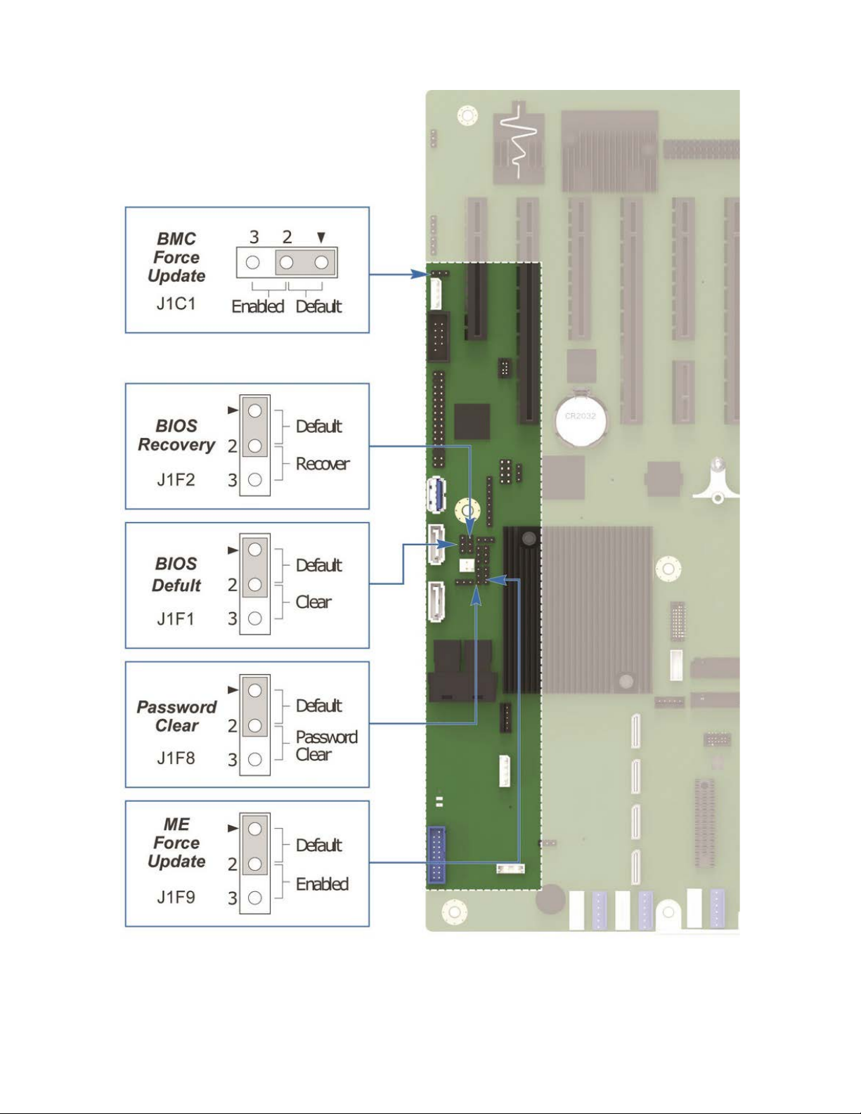
11. Reset and Recovery Jumpers ................................................................................................................................. 94
11.1 BIOS Default Jumper Block ....................................................................................................................................... 95
11.2 Password Clear Jumper Block .................................................................................................................................. 95
11.3 Management Engine (ME) Firmware Force Update Jumper Block ............................................................ 96
11.4 BMC Force Update Jumper Block ........................................................................................................................... 96
11.5 BIOS Recovery Jumper Block ................................................................................................................................... 97
12. Light Guided Diagnostics ........................................................................................................................................ 99
12.1 DIMM Fault LEDs ............................................................................................................................................................ 99
12.2 System LEDs .................................................................................................................................................................. 100
12.2.1 System ID LED .............................................................................................................................................................. 100
12.2.2 System Status LED ...................................................................................................................................................... 100
12.3 Post Code Diagnostic LEDs ..................................................................................................................................... 101
12.4 CPU Fault LEDs ............................................................................................................................................................. 102
12.5 BMC Boot/Reset Status LED Indicators ............................................................................................................. 102
13. Design and Environmental Specifications ........................................................................................................ 103
7

Intel® Server Board S2600ST Product Family Technical Product Specification
13.1 Intel® Server Board S2600ST Design Specifications..................................................................................... 103
Appendix A. Integration and Usage Tips .............................................................................................................. 104
Appendix B. POST Code Diagnostic LED Decoder ............................................................................................. 105
B.1. Early POST Memory Initialization MRC Diagnostic Codes ......................................................................... 106
B.2. BIOS POST Progress Codes .................................................................................................................................... 108
Appendix C. POST Code Errors .............................................................................................................................. 115
C.1. POST Error Beep Codes ........................................................................................................................................... 121
Appendix D. Statement of Volatility...................................................................................................................... 123
Appendix E. Supported Intel Server Chassis ...................................................................................................... 125
E.1. Hot-Swap Backplane (Optional) ............................................................................................................................ 128
E.2. System Level Environmental Limits .................................................................................................................... 129
E.3. Thermal Configuration Tables ............................................................................................................................... 130
Appendix F. Glossary ............................................................................................................................................... 141
8

Intel® Server Board S2600ST Product Family Technical Product Specification
List of Figures
Figure 1. Intel® Server Board S2600STB ......................................................................................................................................... 15
Figure 2. Server board component / feature identification ..................................................................................................... 17
Figure 3. Intel® Server Board S2600ST product family external I/O connector layout ............................................... 18
Figure 4. Intel® Light Guided Diagnostics - DIMM fault LEDs .................................................................................................. 18
Figure 5. Intel® Light Guided Diagnostics – LED identification ............................................................................................... 19
Figure 6. Jumper block identification ............................................................................................................................................... 20
Figure 7. Primary side keep out zone and component height restrictions ....................................................................... 21
Figure 8. Secondary side keep out zone ......................................................................................................................................... 22
Figure 9. Mounting holes ....................................................................................................................................................................... 23
Figure 10. Mounting holes continued ............................................................................................................................................... 24
Figure 11. Major components and connectors (1 of 3) ............................................................................................................. 25
Figure 12. Major components and connectors (2 of 3) ............................................................................................................. 26
Figure 13. Major components and connectors (3 of 3) ............................................................................................................. 27
Figure 14. Intel® Server Board S2600ST product family block diagram ............................................................................ 28
Figure 15. Processor socket assembly ............................................................................................................................................. 32
Figure 16. Processor socket assembly and protective dust cover ....................................................................................... 32
Figure 17. Processor heat sink module (PHM) components and processor socket reference diagram ............... 33
Figure 18. Processor heat sink module (PHM) sub-assembly ................................................................................................ 33
Figure 19. Fully assembled processor heat sink module (PHM) ........................................................................................... 34
Figure 20. Two systems connected through PCIe* Non-Transparent Bridge (NTB) ..................................................... 42
Figure 21. Memory sub-system architecture ................................................................................................................................. 43
Figure 22. Intel® Server Board S2600ST product family memory slot layout ................................................................. 45
Figure 23. Optional Intel® QuickAssist Technology bridge cable installed ...................................................................... 50
Figure 24. Intel® QuickAssist Technology bridge cable – iPC AXXSTCBLQAT ................................................................ 50
Figure 25. PCIe* slots ............................................................................................................................................................................... 51
Figure 26. M.2 connectors ..................................................................................................................................................................... 52
Figure 27. Onboard OCuLink connectors ....................................................................................................................................... 53
Figure 28. Intel® Volume Management Device (Intel® VMD) for NVMe* SSDs ................................................................. 53
Figure 29. VMD support disabled in BIOS setup .......................................................................................................................... 55
Figure 30. VMD support enabled in BIOS setup .......................................................................................................................... 55
Figure 31. Intel® VROC basic architecture overview ................................................................................................................... 56
Figure 32. Intel® VROC upgrade key .................................................................................................................................................. 56
Figure 33. SATA RAID 5 upgrade key ................................................................................................................................................ 61
Figure 34. Network interface connectors ........................................................................................................................................ 61
Figure 35. External RJ45 network interface controller (NIC) port LED definition .......................................................... 62
Figure 36. SFP+ LAN Riser Option...................................................................................................................................................... 62
Figure 37. SFP+ LAN Riser Option Support ................................................................................................................................... 63
Figure 38. BIOS setup security options ............................................................................................................................................ 64
Figure 39. Onboard TPM Connector ................................................................................................................................................. 66
Figure 40. High-level fan speed control process ......................................................................................................................... 76
9

Intel® Server Board S2600ST Product Family Technical Product Specification
Figure 41. Intel® RMM4 Lite placement ............................................................................................................................................ 80
Figure 42. Dedicated Management Port .......................................................................................................................................... 80
Figure 43. Jumper block locations and pins .................................................................................................................................. 94
Figure 44. DIMM fault LEDs ................................................................................................................................................................... 99
Figure 45. System status LED and ID LED identification ....................................................................................................... 100
Figure 46. POST diagnostic LED location and definition ....................................................................................................... 105
Figure 47. Intel® Server Chassis P4304XXMFEN2 feature overview ................................................................................ 125
Figure 48. Intel® Server Chassis P4304XXMUXX feature overview .................................................................................. 126
Figure 49. Chassis-only building block (no front drive bay configuration) .................................................................... 126
Figure 50. Intel® Server Chassis P4304XXMFEN2/P4304XXMUXX front panel .......................................................... 127
Figure 51. P4304XXMFEN2 back panel ........................................................................................................................................ 127
Figure 52. Intel® Server Chassis P4304XXMUXX back panel .............................................................................................. 127
Figure 53. Drive tray LED identification ........................................................................................................................................ 128
10

Intel® Server Board S2600ST Product Family Technical Product Specification
List of Tables
Table 1. Reference Documents ........................................................................................................................................................... 13
Table 2. Intel® Server Board S2600ST product family common feature set ................................................................... 16
Table 3. POST hot keys .......................................................................................................................................................................... 29
Table 4. Intel® Xeon® Processor Scalable Family Feature Comparison .............................................................................. 35
Table 5. Mixed processor configurations error summary ........................................................................................................ 39
Table 6. CPU – PCIe* port routing ...................................................................................................................................................... 41
Table 7. DDR4 RDIMM and LRDIMM support ................................................................................................................................ 44
Table 8. Memory RAS Features ........................................................................................................................................................... 47
Table 9. Intel® VROC upgrade key options ..................................................................................................................................... 57
Table 10. SATA and sSATA Controller Feature Support .......................................................................................................... 57
Table 11. SATA and sSATA controller BIOS utility setup options ........................................................................................ 58
Table 12. Onboard Network interface controller (NIC) LED Definition .............................................................................. 62
Table 13. SFP+ LAN Riser LED Definition ........................................................................................................................................ 63
Table 14. BIOS security configuration TPM states ...................................................................................................................... 67
Table 15. BIOS security configuration TPM administrative controls .................................................................................. 68
Table 16. Power control sources ........................................................................................................................................................ 71
Table 17. ACPI power states ................................................................................................................................................................. 71
Table 18. Component fault LEDs ........................................................................................................................................................ 78
Table 19. Intel® Remote Management Module 4 (Intel® RMM4) options ........................................................................... 79
Table 20. Standard and advanced server management features ......................................................................................... 79
Table 21. Main Power Connector Pin-out (“MAIN_PWR_CONN”) ......................................................................................... 86
Table 22. CPU1 Power Connector Pin-out (“CPU_1_PWR”) ................................................................................................... 87
Table 23. CPU2 Power Connector Pin-out (“CPU_2_PWR”) ................................................................................................... 88
Table 24. Auxiliary Power-in Connector Pin-out ("AUX_PWR_IN”) ...................................................................................... 88
Table 25. Front Panel Header Pin-out .............................................................................................................................................. 88
Table 26. Front Panel USB 3.0 Connector Pin-out ..................................................................................................................... 89
Table 27. SATA 6 Gbps Connector Pin-out .................................................................................................................................... 89
Table 28. Mini-SAS HD Connectors for SATA 6 Gbps Pin-out ............................................................................................... 90
Table 29. M.2 Connector Pin-outs (for SATA & PCIe* modules) ........................................................................................... 91
Table 30. 6-Pin System Fan Connector Pin-out ........................................................................................................................... 92
Table 31. 4-pin System Fan Connector Pin-out ........................................................................................................................... 92
Table 32. CPU Fan Connector Pin-out ............................................................................................................................................. 92
Table 33. I
Table 34. Serial Port A Connector Pin-out ..................................................................................................................................... 93
Table 35. PMBUS Connector Pin-out ............................................................................................................................................... 93
Table 36. Chassis Intrusion Header Pin-out .................................................................................................................................. 93
Table 37. System status LED state detail ..................................................................................................................................... 101
Table 38. BMC Boot/Reset Status LED Indicators .................................................................................................................... 102
Table 39.Server Board Environmental Limits ......................................................................................................................... 103
Table 40. POST progress code LED example ............................................................................................................................. 105
11
2
C Header B Pin-out (“HSBP_I2C_B”) ........................................................................................................................... 93

Intel® Server Board S2600ST Product Family Technical Product Specification
Table 41. MRC progress codes ......................................................................................................................................................... 106
Table 42. MRC Fatal Error Codes ..................................................................................................................................................... 107
Table 43. POST progress codes ....................................................................................................................................................... 108
Table 44. POST error codes and messages ................................................................................................................................ 116
Table 45. POST error beep codes ................................................................................................................................................... 121
Table 46. Integrated BMC beep codes .......................................................................................................................................... 122
Table 47. Volatile and non-volatile components on the Intel® Server Board S2600ST product family ........... 123
Table 48. Volatile and non-volatile components on the LAN riser ................................................................................... 123
Table 49. Drive status LED states .................................................................................................................................................... 128
Table 50. Drive activity LED states .................................................................................................................................................. 128
Table 51. PCIe* SSD drive status LED states .............................................................................................................................. 128
Table 52. Environmental Limits ....................................................................................................................................................... 129
Table 53. System in “Normal” Operating Mode for Systems with Fan Redundancy ................................................. 131
Table 51. System in “Fan Fail” Operating Mode for Systems with Fan Redundancy ................................................ 134
Table 52. System in “Normal” Operating Mode for Systems without Fan Redundancy .......................................... 137
Table 53. System in “Throttling” Operating Mode for Systems with Fan Redundancy ............................................ 140
12

Intel® Server Board S2600ST Product Family Technical Product Specification
Document
Classification
Intel® Server System BMC Firmware External Product Specification for Intel® Xeon®
processor Scalable family
Intel® Server System BIOS External Product Specification for Intel® Xeon® processor
Scalable family
Intel® C620 Series Chipset Platform Controller Hub External Design Specification
Intel Confidential
Intel® Xeon® processor Scalable Family Server Processor External Design Specification
Volume 1, Volume 2 Part A, Volume 2 Part B, Volume 3
Advanced Configuration and Power Interface Specification. Revision 3.0 (2004)
http://www.acpi.info/
Intelligent Platform Management Interface Specification, v2.0 (2004)
Public
Intelligent Platform Management Bus Communications Protocol Specification, v1.0
(1998)
Platform Support for Serial-over-LAN (SOL), TMode, and Terminal Mode External
Architecture Specification, Version 1.1 (2002)
Intel® Remote Management Module User Guide
Public
Alert Standard Format (ASF) Specification, Version 2.0 (2003), ©2000-2003,
Distributed Management Task Force, Inc., http://www.dmtf.org
SmaRT & CLST Architecture on Intel Systems and Power Supplies Specification
Public
Intel® Remote Management Module 4 Technical Product Specification
Public
Intel® Remote Management Module 4 and Integrated BMC Web Console User Guide
Public
1. Introduction
This Technical Product Specification (TPS) provides a high level overview of the features, functions, and
architecture of the Intel® Server Board S2600ST product family.
For more in-depth technical information, refer to the documents listed in Table 1.
Note: Some of the documents listed in the following table are classified as “Intel Confidential”. These
documents are made available under a Non-Disclosure Agreement (NDA) with Intel and must be ordered
through your local Intel representative.
Table 1. Reference Documents
Document Title
Intel Confidential
Intel Confidential
Intel Confidential
Public
Public
Public
Public
13

Intel® Server Board S2600ST Product Family Technical Product Specification
1.1 Chapter Outline
This document is divided into the following chapters:
• Chapter 1 – Introduction
• Chapter 2 – Server Board Overview
• Chapter 3 – Processor Support
• Chapter 4 – PCI Express* (PCIe*) Support
• Chapter 5 – Memory Support
• Chapter 6 – System I/O
• Chapter 7 – System Security
• Chapter 8 – Platform Management
• Chapter 9 – Standard and Advanced Server Management Features
• Chapter 10 – On-Board Connector and Header Overview
• Chapter 11 – Reset and Recovery Jumpers
• Chapter 12 – Light-Guided Diagnostics
• Chapter 13 – Design and Environmental Specifications
• Appendix A – Integration and Usage Tips
• Appendix B – Post Code Diagnostic LED Decoder
• Appendix C – Post Code Errors
• Appendix D – Statement of Volatility
• Appendix E – Supported Intel Server Chassis
• Appendix F – Glossary
1.2 Intel® Server Board Use Disclaimer
Intel® Server Boards support add-in peripherals and contain a number of high-density very large scale
integration (VLSI) and power delivery components that need adequate airflow to cool. Intel ensures through
its own chassis development and testing that when Intel server building blocks are used together, the fully
integrated system will meet the intended thermal requirements of these components. It is the responsibility
of the system integrator who chooses not to use Intel developed server building blocks to consult vendor
datasheets and operating parameters to determine the amount of airflow required for their specific
application and environmental conditions. Intel Corporation cannot be held responsible if components fail
or the server board does not operate correctly when used outside any of its published operating or nonoperating limits.
14
Intel® Server Board S2600ST Product Family Technical Product Specification
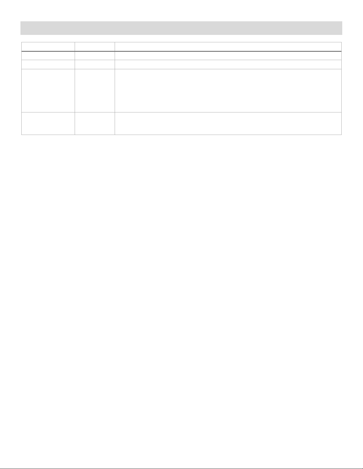
2. Server Board Family Overview
The Intel® Server Board S2600ST product family is a monolithic printed circuit board assembly with features
that are intended for flexibility in scalable performance environments. This server board is designed to
support the Intel® Xeon® processor Scalable family. Previous generation Intel® Xeon® processors are not
supported.
Figure 1. Intel® Server Board S2600STB
15

Intel® Server Board S2600ST Product Family Technical Product Specification
Intel® Server Board Feature
iPC – S2600STB
iPC –S2600STQ
Processor
2 – LGA3647-0 (Socket P) processor sockets
Note: Previous generation Intel® Xeon® processors are not supported.
Memory
16 total DIMM slots
DDR4 standard voltage of 1.2 V
Intel® C62x Series Chipset
Intel® C624 Chipset
Intel® C628 Chipset
Intel® QuickAssist Technology
No
Yes
Local Area Network (LAN)
Dual port RJ45 10 GbE on board
Optional riser aligned to Slot 5 with two 10 Gb SFP+ connectors
Onboard PCIe* NVMe*
• (4) – OCuLink connectors
(accessory option)
• (2) – OCuLink connectors
option)
Onboard SATA
12 x SATA 6 Gbps ports (6 Gb/s, 3 Gb/s and 1.5 Gb/s transfer rates are supported)
PCIe* Add-in Card Slots
• Slot 1: PCIe* 3.0 x8 slot (x8 electrical) handled by CPU2
• Slot 6: PCIe* 3.0 x16 slot (x16 electrical) handled by CPU1 (riser capable)
Video
• Integrated 2D video controller
(1) – DB-15 external connector
USB
• (2) – external USB 2.0 ports
(1) – 2x10 pin connector providing front panel support for (2) USB 2.0 / 3.0 ports
Serial Port
(1) – internal DH-10 serial port A connector
Server Management
• Integrated baseboard management controller, IPMI 2.0 compliant
• Advanced server management via Intel® RMM4 Lite (accessory option)
Security
Trusted platform module 2.0 (Rest of World) – iPC- AXXTPMENC8 (accessory option)
Trusted platform module 2.0 (China Version) – iPC- AXXTPME8 (accessory option)
System Fan Support
• (2) – 4-pin processor fan headers
• (1) – 4-pin rear system fan header
2.1 Server Board Feature Set
Table 2. Intel® Server Board S2600ST product family common feature set
Supports (1) or (2) Intel® Xeon® processor Scalable family with maximum TDP of 205 W.
2 UPI* links between processors
8 DIMM slots across 6 memory channels per processor
• 1 DIMM slot per memory channel on 4 channels
• 2 DIMM slots per memory channel on 2 channels
Supported memory: Registered DDR4 (RDIMM), Load Reduced DDR4 (LRDIMM)
Memory data transfer rate up to 2666 MT/s (processor SKU dependent)
• Intel® VMD support
• Intel® RSTe VROC support
• (2) – single port 7-pin SATA connectors
• (2) – M.2 connectors – SATA / PCIe*
• (2) – 4-port mini- SAS high density (HD) (SFF-8643) connectors
Embedded SATA software RAID
• Intel® RSTe 5.0
• Intel® Embedded Server RAID Technology 2 1.60 with optional RAID 5 key support (see
section 6.3.6 for details)
• Slot 2: PCIe* 3.0 x16 slot (x16 electrical) handled by CPU2 (riser capable)
• Slot 3: PCIe* 3.0 x8 slot (x8 electrical) handled by CPU2
• Slot 4: PCIe* 3.0 x16 slot (x16 electrical) handled by CPU2
• Slot 5: PCIe* 3.0 x8 slot (x8 electrical) handled by CPU1
• 16 MB of DDR4 video memory
•
• (2) – external USB 3.0 ports
• (1) – internal USB 3.0 type A connector
•
• Intel® VMD support
• Intel® RSTe VROC support (accessory
• Support for Intel® Server Management software
• Dedicated onboard RJ45 management port
16
• (6) – 6-pin front system fan headers

Intel® Server Board S2600ST Product Family Technical Product Specification
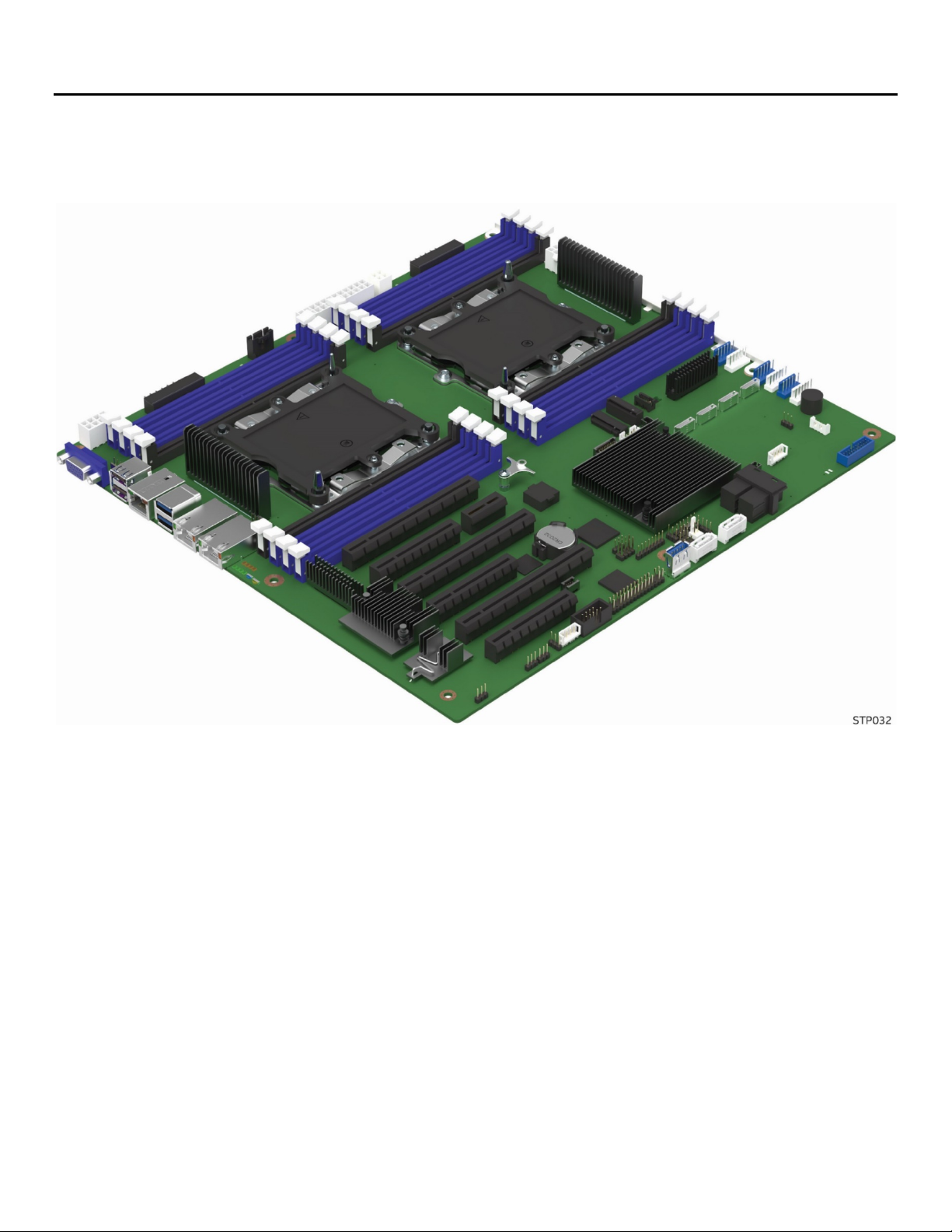
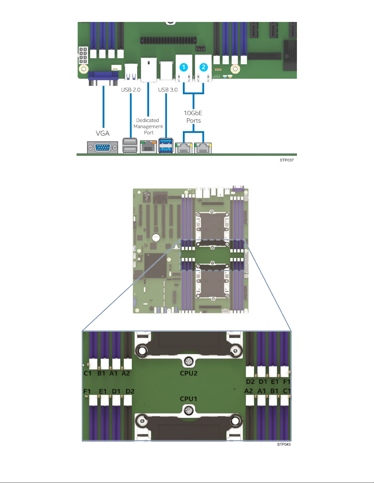
2.2 Server Board Component / Feature Identification
Figure 2. Server board component / feature identification
17
Intel® Server Board S2600ST Product Family Technical Product Specification
Figure 3. Intel® Server Board S2600ST product family external I/O connector layout
Figure 4. Intel® Light Guided Diagnostics - DIMM fault LEDs
18
Intel® Server Board S2600ST Product Family Technical Product Specification
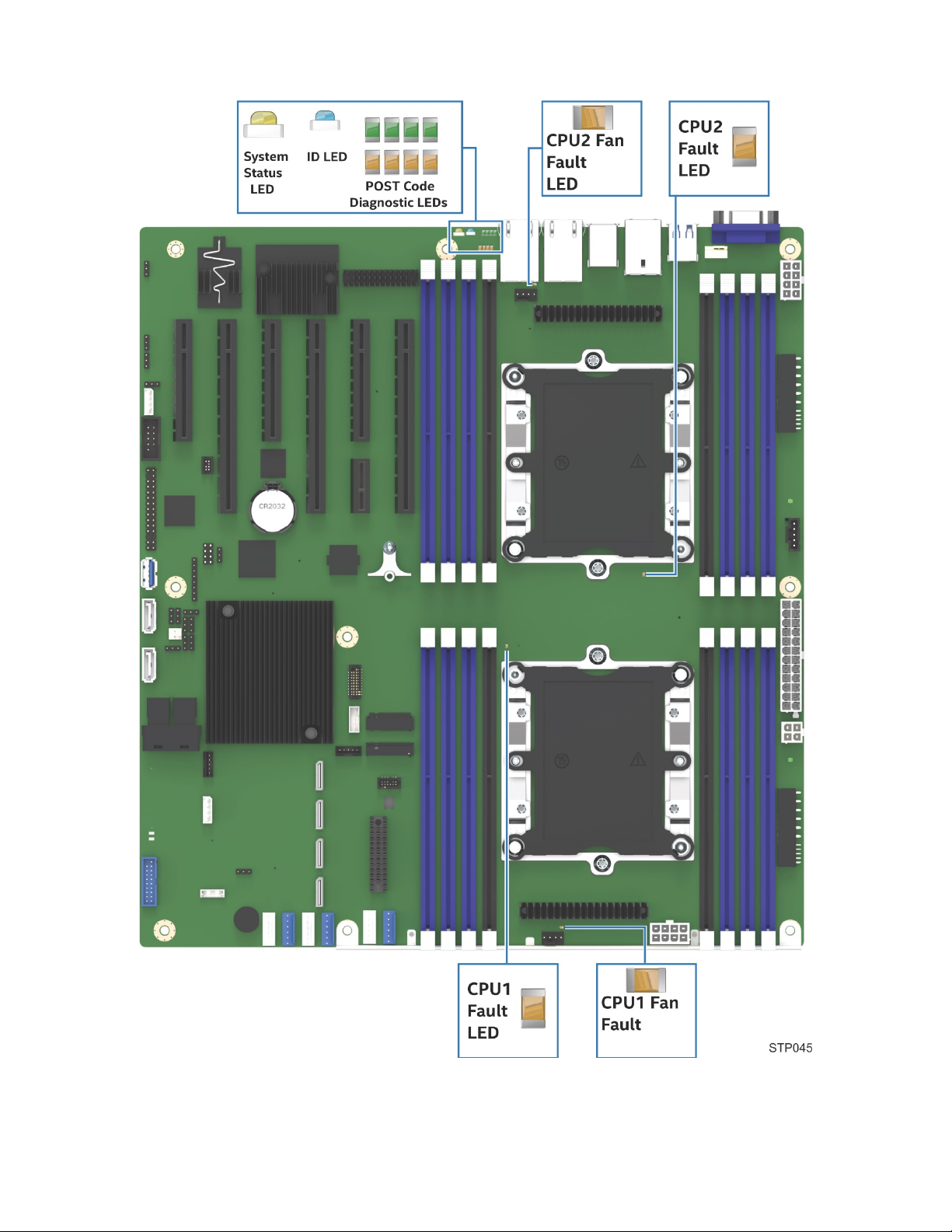
Figure 5. Intel® Light Guided Diagnostics – LED identification
19
Intel® Server Board S2600ST Product Family Technical Product Specification
Figure 6. Jumper block identification
See Chapter 11 for additional details on reset and recovery jumpers.
20
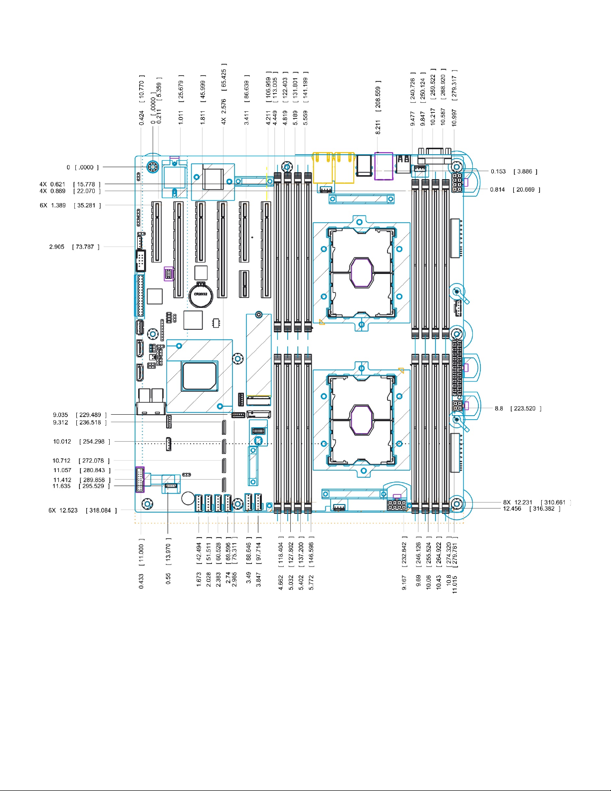
Intel® Server Board S2600ST Product Family Technical Product Specification
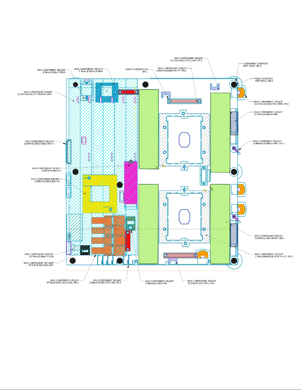
2.3 Server Board Mechanical Drawings
Figure 7. Primary side keep out zone and component height restrictions
21
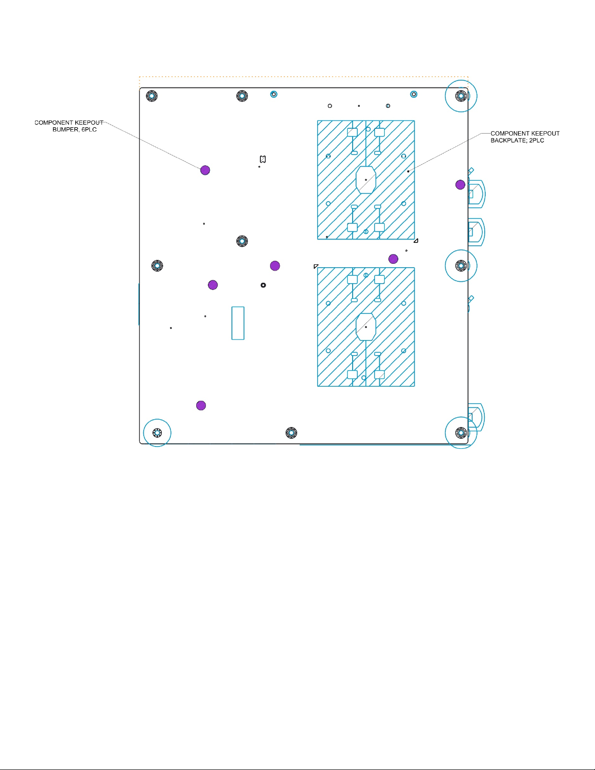
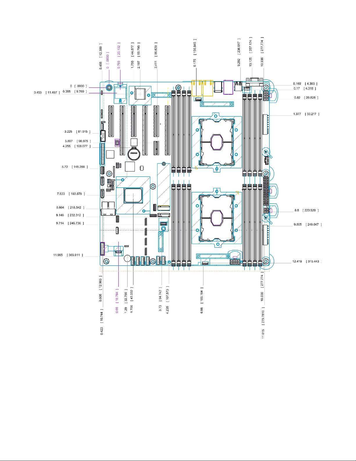
Intel® Server Board S2600ST Product Family Technical Product Specification
Figure 8. Secondary side keep out zone
22
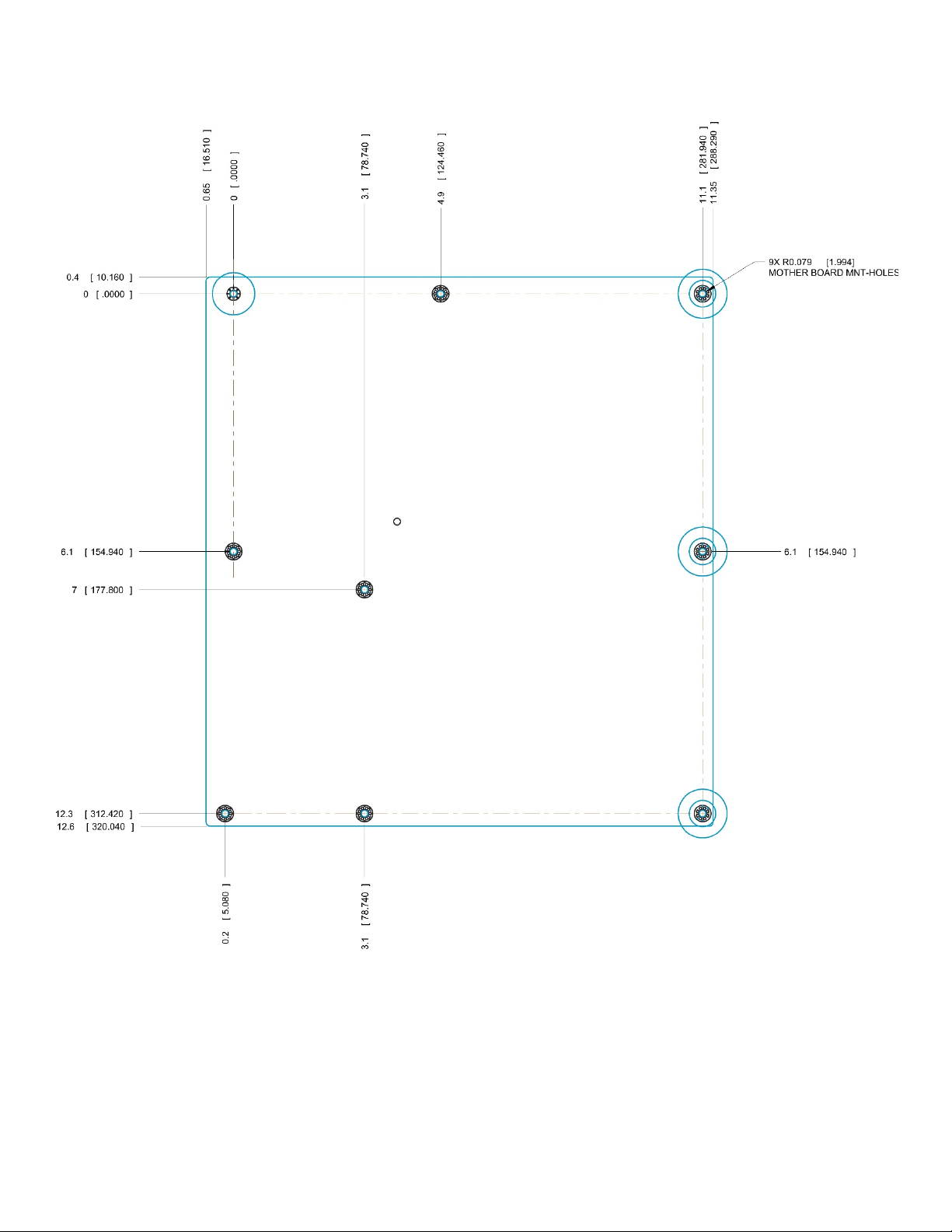
Intel® Server Board S2600ST Product Family Technical Product Specification
Figure 9. Mounting holes
23
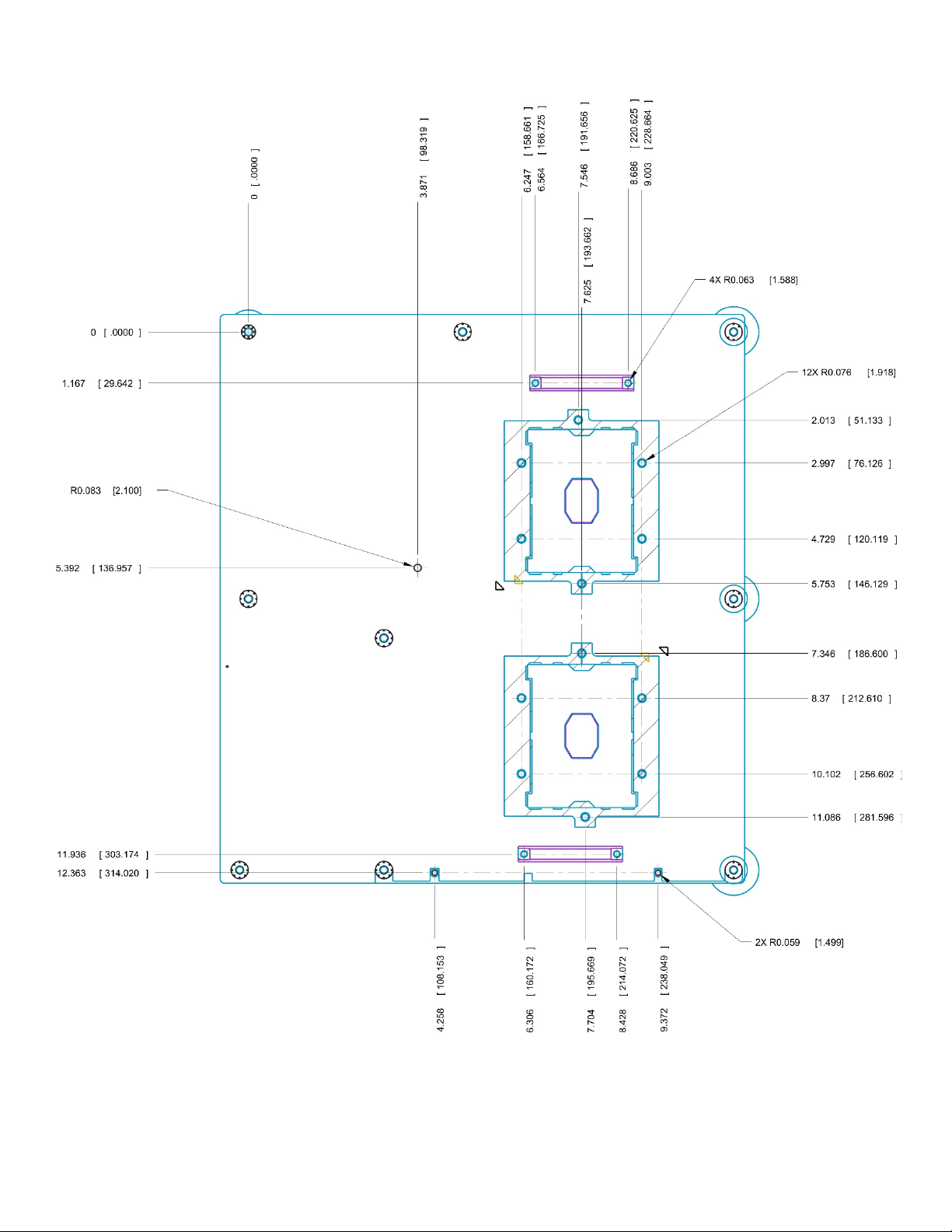
Intel® Server Board S2600ST Product Family Technical Product Specification
Figure 10. Mounting holes continued
24
Intel® Server Board S2600ST Product Family Technical Product Specification
Figure 11. Major components and connectors (1 of 3)
25
Intel® Server Board S2600ST Product Family Technical Product Specification
Figure 12. Major components and connectors (2 of 3)
26

Intel® Server Board S2600ST Product Family Technical Product Specification
Figure 13. Major components and connectors (3 of 3)
27
Intel® Server Board S2600ST Product Family Technical Product Specification
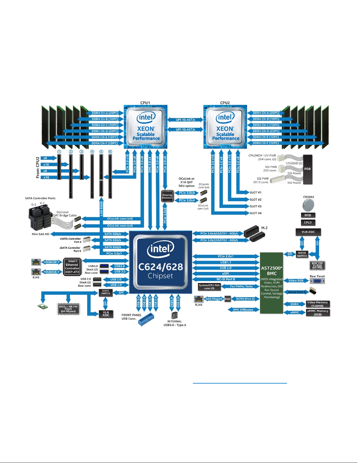
2.4 Product Architecture Overview
The architecture of the Intel® Server Board S2600ST product family is developed around the integrated
features and functions of the Intel® Xeon® processor Scalable family, the Intel® C624 and C628 chipsets, and
the Aspeed* AST2500 Baseboard Management Controller (BMC).
The following diagram provides an overview of the server board architecture, showing the features and
interconnects of each of the major sub-system components.
Figure 14. Intel® Server Board S2600ST product family block diagram
2.5 System Software Stack
System software is pre-programmed by Intel on the server board during the board assembly process,
making the server board functional at first power on after system integration. However, to ensure the most
reliable system operation, it is highly recommended to visit http://downloadcenter.intel.com
available system updates.
System updates can be performed in a number of operating environments, including the embedded Unified
Extensible Firmware Interface (UEFI) shell using the UEFI only System Update Package (SUP), or under Intel
supported operating systems using the Intel® One Boot Flash Update (Intel® OFU) utility.
28
for the latest

Intel® Server Board S2600ST Product Family Technical Product Specification
Hot Key
Function
<F2>
Enter the BIOS setup utility
<F6>
Pop-up BIOS boot menu
<F12>
Network boot
<Esc>
Switch from logo screen to diagnostic screen
<Pause>
Stop POST temporarily
As part of the initial system integration process, system integrators must program system configuration data
onto the server board using the Field Replaceable Unit / Sensor Data Record (FRUSDR) utility to ensure the
embedded platform management subsystem is able to provide the best performance and cooling for the
final system configuration. The FRUSDR utility is included in the uEFI SUP and Intel OFU packages.
Refer to the following Intel documents for more in-depth information about the system software stack and
their functions:
• Intel® Server System BMC Firmware External Product Specification for Intel® Xeon® Processor Scalable
Family – Intel NDA Required
• Intel® Server System BIOS External Product Specification for Intel® Xeon® processor Scalable family –
Intel NDA Required
2.5.1 Hot Keys Supported During Power-On Self-Test (POST)
Certain hot keys are recognized during power-on self-test (POST). A hot key is a key or key combination that
is recognized as an unprompted command input by the system operator. In most cases, hot keys are
recognized even while other processing is in progress.
The Basic Input/Output System (BIOS) supported hot keys are only recognized by the BIOS during the
system boot time POST process. BIOS supported hot keys are no longer recognized once the POST process
has completed and the operating system boot process has begun.
Table 3 provides a list of BIOS supported hot keys.
Table 3. POST hot keys
2.5.1.1 POST Logo and Diagnostic Screens
With the BIOS Setup Utility set to Quiet Boot (default), the BIOS will display a splash screen to the display
monitor during the POST process. Pressing the <ESC> key will close the splash screen and open a POST
Diagnostic / Information screen in its place.
The factory default splash screen is that of an Intel Logo. A custom OEM splash screen can be installed to a
designated flash memory location to over-ride the factory default.
If a splash screen is not present in the BIOS flash memory space, or if Quiet Boot is disabled in BIOS Setup,
the POST diagnostic screen is displayed during POST with a summary of the system configuration
information. The POST diagnostic screen is purely a text mode screen, as opposed to the graphics mode
logo screen.
If console redirection is enabled in the BIOS setup utility, the quiet boot setting is disregarded and the text
mode diagnostic screen is displayed unconditionally. This is due to the limitations of console redirection,
which transfers data in a mode that is not graphics-compatible.
29

Intel® Server Board S2600ST Product Family Technical Product Specification
2.5.1.2 BIOS Boot Pop-Up Menu
The BIOS Boot Specification (BBS) provides a boot pop-up menu that can be invoked by pressing the <F6>
key during POST. The BBS pop-up menu displays all available boot devices. The boot order in the pop-up
menu is not the same as the boot order in the BIOS setup utility. The pop-up menu simply lists all of the
available devices from which the system can be booted, and allows a manual selection of the desired boot
device.
When an Administrator password is installed in the BIOS setup utility, the Administrator password is
required to access the boot pop-up menu. If a User password is entered, the user is taken directly to the boot
manager in the BIOS setup utility only allowing the system to boot in the order previously defined by the
administrator.
2.5.1.3 Entering BIOS Setup
To enter the BIOS setup utility using a keyboard (or emulated keyboard), press the <F2> function key during
boot time when the OEM or Intel logo screen or the POST diagnostic screen is displayed.
The following instructional message is displayed on the diagnostic screen or under the quiet boot logo
screen:
Press <F2> to enter setup, <F6> Boot Menu, <F12> Network Boot
Note: With a USB keyboard, it is important to wait until the BIOS discovers the keyboard and beeps; until the
USB controller has been initialized and the keyboard activated, key presses are not read by the system.
When the BIOS setup utility is entered, the main screen is displayed initially. However, if a serious error
occurs during POST, the system enters the BIOS setup utility and displays the error manager screen instead
of the main screen.
Refer to the following Intel document for additional BIOS setup utility information:
• Intel® Server System BIOS External Product Specification for Intel® Xeon® processor Scalable family –
Intel NDA Required
2.5.2 BIOS Update Capability
To bring BIOS fixes or new features into the system, it is necessary to replace the current installed BIOS
image with an updated one. The BIOS image can be updated using a standalone IFLASH32 utility in the UEFI
shell or using the OFU utility program under a supported operating system. Full BIOS update instructions are
provided with update packages downloaded from the Intel website.
2.5.3 BIOS Recovery
If a system is unable to boot successfully to an OS, hangs during POST, or even hangs and fails to start
executing POST, it may be necessary to perform a BIOS recovery procedure to replace a defective copy of
the primary BIOS
The BIOS provides three mechanisms to start the BIOS recovery process, which is called recovery mode:
• The recovery mode jumper causes the BIOS to boot in recovery mode. See Figure 6 for jumper
location.
• At power on, if the BIOS boot block detects a partial BIOS update was performed, the BIOS
automatically boots in recovery mode.
• The baseboard management controller (BMC) asserts the recovery mode general purpose
input/output (GPIO) in case of partial BIOS update and FRB2 timeout.
30
Loading...