


Intel845GL/GV Main board
User’s Manual
Rev: 1.0/1.2
PCB: M248
CONTENTS
CHAPTER 1 PACKAGE CONTENTS………………….…………………
CHAPTER 2 INTRODUCTION……………………….…………………...
CHAPTER 3 MAIN BOARD LOCATIONS……………………………….
CHAPTER 4 INSTALLATION…………………………….………………
4.1JUMPER SETTING AND SLOT…………………….………………
4.2CPU INSTALLATION……………………………………………….
4.3MEMORY INSTALLATION………………………………………..
4.4IDE DEVICES INSTALLATION…………………………………...
4.5OTHER DEVICE INSTALLATION………………………………...
CHAPTER 5 DRIVE INSTALLATION……………………………………
5.1INSTALLATION DIRECTORY…………………………………….
5.2INTEL CHIPSET SOFTWARE SETUP……………………………..
5.3IAA (INTEL APPLICATION ACCELERATOR) SETUP…………..
5.4SOUND DRIVER SETUP………………...………………………….
5.5USB 2.0 DRIVER SETUP……………………………………………
CHAPTER 6 BIOS SETUP…………………………………………………
6.1MAIN MENU…………………………………………………………
6.2STANDARD CMOS FEATURES……………………………………
6.3ADVANCED BIOS FEATURES……………………………………..
6.4ADVANCED CHIPSET FEATURES…………………………………
6.5INTEGRATED PERIPHERALS………………………………………
6.6POWER MANAGEMENT SETUP……………………………………
6.7PNP/PCI CONFIGURATIONS………………………………………..
6.8FREQUENCY/VOLTAGE CONTROL……………………………….
6.9LOAD FAIL-SAFE DEFAULTS………………………………………
6.10LOAD OPTIMIZED DEFAULTS……………………………………..
6.11CHANGE PASSWORD………………………………………………..
6.12SAVE EXIT & WITHOUT SAVE EXIT SETUP……………………..
Chapter 1 Package Contents
Your main board package contains the following items:
1.One M248 Rev:1.0/1.2 main board
2.One 80-Pin Ultra DMA 66/100 IDE drive ribbon cable
3.One 34-Pin Floppy drive ribbon cable
4.One front panel connector ribbon cable (optional)
5.Software Install CD
6.One user’s manual
Chapter 2 Introduction
This main board has the Intel 845GL/GV chipset that contains Intel 82845GL/GV Memory Controller Hub and Intel 82801DB I/O Controller Hub. This main board has a Socket-478 support for Intel Pentium 4 processors with front-side bus (FSB) speeds up to 400/533, supports DDR200/DDR266 memory bus, supports AC97 audio codec, integrated AC97 audio that supports full surround sound with up to six channels, front panel audio output function, provides Ultra DMA66/100 function, the integrated display function technologies without extend display card, provides three PCI slots. The main board integrated main board, VGA card, sound card three function all in one.
Key Features: -Chipset:
Intel 845GL/GV chipset GMCH: Intel 82845GL/GV; ICH4: Intel 82801DB (DBM)
-Processor:
Supports Intel Celeron CPU Socket 478 CPU
Supports Intel Pentium 4 (Northwood) Socket 478 CPU Supports Intel Pentium 4 (Willamette) Socket 478 CPU Supports Intel Pentium 4 (Prescott) Socket 478 CPU Supports Intel Celeron D (Prescott) Socket 478 CPU
-Supports 400/533MHz HOST BUS Frequency
-Memory Support:
Supports DDR200/DDR266 (Double Data Rate) SDRAM Two 184-pin DIMM slots for DDR SDRAM memory modules
-Integrated display function technologies without extend VGA card Integrated 2D/3D Graphics Controller
-USB Ports
Six USB ports
Supports compliant with Universal Serial Bus Specification Revision 2.0
-BIOS Supports
Supports Plug and Play
Supports Advanced Power Management Interface
-IDE Port
Provides two channel connecting four IDE drives Supports Ultra ATA66/100 synchronous DMA modes
-I/O Ports
One Floppy port support format 360k/720k/1.2M/1.44M/2.88M disk driver One serial port
One parallel port
Six USB ports (two back-panel USB ports, onboard USB headers providing Maximum four extra ports)
One PS/2 Keyboard port One PS/2 Mouse
One Game/MIDI port
One IrDA port support 115.2KB/S transfers’ data.
-Onboard Sound AC’97 2.2 specification compliant Support 16bit stereo codec
Multiple stereo input mixers
Provides onboard Line-in Jack, Microphone-in Jack
-Expansion Slot
Three PCI slots 2.2 specifications compliant
-Hardware detects function (Optional)
Auto detect CPU Voltage and CPU Temperature Auto detect CPU FAN and Power FAN speed
-Other function
Supports Wake-on-LAN Supports Wake-on-Modem
-Dimension
Micro ATX form factor

Chapter 3 Main board Locations
Chapter 4 Installation
4.1 Jumper Setting and Slot
FSB CPU Frequency Jumper Setting
JUMPER |
AUTO (Default) |
400 |
533 |
JP1 |
1-2 |
2-3 |
OPEN |
JP3: Clear CMOS Jumper Setting |
|
|
|
1-2 (Default) |
|
Normal |
|
2-3 |
|
Clear CMOS |
|
Audio: Front panel Jumper setting
PIN |
Function |
PIN |
Function |
1 |
MIC+ |
2 |
Ground |
3 |
Vbias |
4 |
AuD_Vcc (AVCC) |
5 |
AuD_R_Out |
6 |
AuD_R_Out Back |
7 |
N.C. |
8 |
Key |
9 |
AuD_L_Out |
10 |
AuD_L_Out Back |
Note: 5-6, 9-10 pin short is default. (Reference main board bitmap)
USB: Expansion Connector
PIN |
Function |
PIN |
Function |
1 |
VCC: Power |
2 |
Ground |
3 |
D-: Data – Signal |
4 |
AuD_Vcc (AVCC) |
5 |
D+: Data + Signal |
6 |
AuD_R_Out Back |
7 |
GND: Ground |
8 |
Key |
9 |
KEY |
10 |
AuD_L_ Back |
Expansion Slots |
|
|
|
DDR1/DDR2 |
184 Pin DDR Memory Slots |
||
PCI1/PCI2/PCI3 |
32 bit PCI BUS Expansion Slots |
||
Socket 478 |
Socket 478 CPU Slots |
||
Connectors
PS/2 (Bottom) |
|
PS/2 Keyboard (Down Purple) |
|
PS/2 (Top) |
|
PS/2 Mouse Header (Up Green) |
|
USB 0/1 |
|
USB 0/1 Connector Port |
|
USB 2/3 |
|
USB 2/3 Connector Port |
|
LPT |
|
Printer Connector Port |
|
VGA |
|
VGA Display Connector Port |
|
COM1 |
|
Serial Ports COM1 Connector Port |
|
GAME/MIDI |
|
Game/MIDI Port |
|
LINE OUT/LINE IN/MIC |
|
Audio Output/Audio Input/Microphone |
|
CD_IN |
|
CD-ROM Audio Input Port |
|
IDE1/IDE2 |
|
Primary IDE/Secondary IDE Port |
|
FDD |
|
Floppy Disk Drive Connector Port |
|
PW1 |
|
ATX_20 Power Supply Connector Port |
|
PW2 |
|
ATX_4 Power Supply Connector Port |
|
FAN ½ |
|
CPU System Fan Port |
|
IrDA |
|
IrDA Infrared Port |
|
Function Port Pane1 |
|
|
|
|
|
|
|
Power Supply LED |
Pin 1:Power Supply Anode; Pin 3: Ground |
||
|
|
|
|
HDD LED |
Pin 2: Power Supply Anode; Pin 4: LED Signal |
|
|
|
|
|
|
ATX Power Supply Switch |
Pin 8: Switch Signal; Pin 10: Power Supply |
|
|
|
Anode |
|
|
Reset Switch |
Pin 14: Ground; Pin 16:Reset Signal |
|
|
|
|
|
|
Speaker Input |
Pin 9: Speaker Audio Input; Pin 15 : Power |
|
|
|
Supply Anode |
|
|
4.2 CPU Installation |
|
|
|
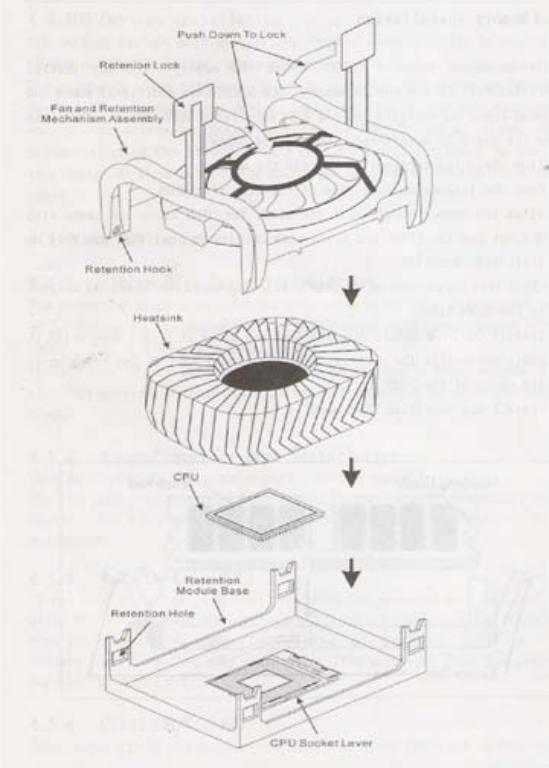
This main board has a socket 478 processor socket. Follow these instructions to install the CPU:
1.Unhook the CPU socket’s locking lever pulling it away from socket and raising it to the upright position.
2.Match the pin 1 corner of CPU socket to the one of processor, and insert the processor into the socket. Do not use force.
3.Push the locking lever down and hook it under the latch on the edge of socket.
4.Apply thermal grease to the top of the CPU.
5.Lower the CPU fan/heat sink unit onto the CPU and CPU socket, and then use the retention module clamps to snap the fan/heat sink into place.
6.Plug the CPU fan power cable into the CPU cooling fan power supply connector on the main board.
4.3 Memory installation
This main board supports DDR200/DDR266 DDR memory you may install 64/128/256/512MB 184 pin DDR memory. DDR SDROM uses additional power and ground lines and requires 184-pin 2.5V unbuffered DIMM module rather than the 168pin 3.3V unbuffered DIMM used by SDRAM.
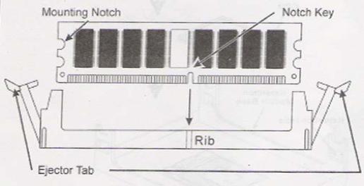
Follow these instructions to install the Memory:
1.Push the latches on each side of the DIMM slot down.
2.Align the memory module with the slot. The DIMM slots are keyed with notches and the DIMMS are keyed with cutouts so that they can only be installed correctly.
3.Check that the cutouts on the DIMM module edge connector match the notches in the DIMM slot.
4.Install the DIMM module into the slot and press it firmly down until it seats correctly. The slot latches are levered upwards and latch on to the edges of the DIMM.
5.Install any remaining DIMM modules.
4.4 IDE Devices Installation
IDE devices include hard disk drives, high-density diskette drives, and CD-ROM or DVD-ROM drives, among others.
The main board ships with an IDE cable that can support one or two IDE devices. If you connect two devices to a single cable, you must configure one of the drives as Master and one of the drives as Slave. The documentation of the IDE device will tell you how to configure the device as a Master or Slave device. The Master device connects to the end of the cable.
4.5 Other Device Installation
4.5.1 Floppy Disk Drive Installation
This main board ships with a floppy disk drive cable that can support one or two drives. Drives can be 3.5” or 5.25” wide, with capacities of 360K, 720K, 1.2MB, 1.44MB, or 2.88MB.
Install your drives and connect power from the system power supply. Use the cable provided to connect the drives to the floppy disk drive connector floppy.
4.5.2 Sound Connector Port Installation
This main board has three audio ports connects audio device.
The left side jack (green) is for a stereo line-out signal. The middle jack (gray) is for a stereo line-in signal. The right side jack (red) is for a microphone.
4.5.3 Wake on LAN (WOL)
If you have installed a LAN card, use the cable provided with the card to plug into the main board WOL connector. This enables the Wake on LAN feature. When you system is in a power saving mode, any LAN signal automatically resumes the system. You must enable this item using the power Management page of the Setup Utility.
4.5.4 Clear CMOS (JP3)
This jumper allows you to clear the Real Time Clock (RTC) RAM in CMOS. You can clear the CMOS memory of date, time, and system setup parameters by erasing the CMOS RTC RAM data. The RAM data in CMOS, that include system setup information such as system passwords, is powered by the onboard button cell battery.
1.Turn OFF the computer and unplug the power cord.
2.Move the jumper cap from pin 1-2(default) to pin 2-3. Keep the cap on pin 2-3 for about 5-10 seconds, and then move the cap back to pinsl-2.
3.Plug the power cord and turn ON the computer.
4.Hold down the <DEL> key during the boot process and enter BIOS setup to re-enter data.
Note1: Except when clearing RTC RAM, never remove the cap on CLRTC1 jumper default position. Removing the cap will cause system boot failure!
Note2: You do not need to clear the RTC when the system hangs due to over clocking. For system failure due to over clocking, use the C.P.R. (CPU Parameter Recall) feature. Shut down and reboot the system so BIOS can automatically reset parameter settings to defaults values.
4.5.5 ATX Power connectors (20-pin ATXPWRI, 4-pin ATX 12V1)
 Loading...