


2442-222
Table of contents
 Loading...
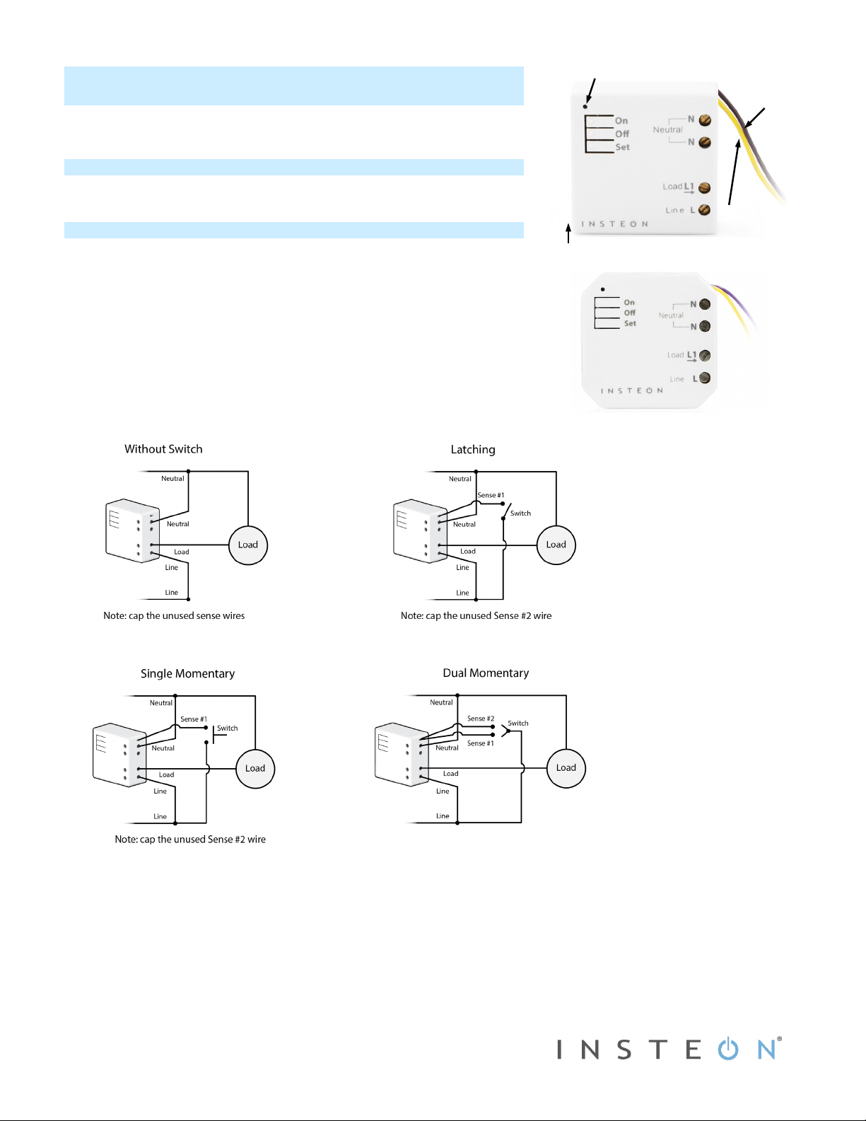
2442-222, 2442-422, 2442-522 Rev. 6/3/2013 11:07 AM / See Owner’s Manual for Warranty Information.
Protected under U.S. and foreign patents (see www.insteon.com/patents)
© Copyright 2013 INSTEON, 16542 Millikan Ave., Irvine, CA 92606, 866-243-8022
Quick Start Guide
INSTEON
®
Micro Dimmer
Models: 2442-222, 2442-422, 2442-522
Tools Needed
• Slotted #1 screwdriver • Voltage meter
• Philips screwdriver • Wire cutter/stripper
Installing Micro Module
Installation should only be performed by a qualified electrician or a homeowner
who is familiar and comfortable with electrical circuitry. If you have questions,
consult an electrician or call the INSTEON Support Line at 866-243-8022
1) Write down the INSTEON ID found on the back of the unit (XX.XX.XX)
2) Turn off breaker/fuse and verify that the power is off
3) Disconnect wires from existing switch, fixture or outlet and prep all wires to be
connected to Micro module, with 3/16” (5mm) of bare wire on the ends
4) Connect wires per diagram which corresponds to your installation
Note: sense lines carry very low current (~0.35mA 240V, ~0.17mA for 120V)
5) After ensuring wires are firmly connected and that there is no exposed wire, turn on breaker/fuse
After a few seconds, load will turn on (if wired into switch or fixture) and Micro module LED will turn green
6) Test by tapping Micro module on/off buttons
Load will turn on and off
Micro Module LED will turn green when load is on and red when load is off
7) If installing a single momentary or dual momentary switch
a) Press and hold set button until it beeps
LED will start blinking green
b) Press and hold set button until it beeps a second time
LED will start blinking red
c) Press and hold set button until it beeps a third time
EU/AUS/NZ
North America
Sense #1
(yellow)
Sense #2
(purple)
LED
Antenna
Loading...