


HP -3000/4000
Terminal User’s Guide

This equipment has been tested and found to comply with the limits for a Class B digital device, pursuant to part 15 of the FCC Rules. These limits are designed to provide reasonable protection against harmful interference when the equipment is operated in a commercial environment. This equipment generates, uses, and can radiate radio frequency energy, and, if not installed and used in accordance with the Installation Manual, may cause harmful
interference to radio communications. Operation of this equipment in a residential area is likely to cause harmful interference, in which case the user will be required to correct the interference at the user’s own expense.
This Class A digital apparatus meets all requirements of the Canadian Interference-Causing
Equipment Regulations.
Cet appareil numerique de la classe A respecte toutes les exigences du Reglemente sure le materiel brouilleur du Canada.
© 1998 through 2009 Schlage Biometrics, Inc. – ALL RIGHTS RESERVED
Document Part Number: 70100-6003 – Revision 3.1 – June, 2009
HandPunch is a trademark of Schlage Biometrics, Inc.
The trademarks used in this Manual are the property of the trademark holders. The use of these trademarks in this Manual should not be regarded as infringing upon or affecting the validity of any of these trademarks.
Schlage Biometrics, Inc. reserves the right to change, without notice, product offerings or specifications.
No part of this publication may be reproduced in any form without the express written permission from Schlage Biometrics, Inc.

Table of Contents
Introduction |
3 |
Biometrics |
4 |
Principle of Operation |
4 |
Specifications |
7 |
Planning an Installation |
11 |
Site Preparation |
11 |
HandPunch Placement |
11 |
Wiring |
12 |
Power Input |
12 |
Battery Backup |
12 |
Earth Ground and Shielding |
13 |
Communications |
18 |
External Devices |
20 |
Mechanical Installation |
23 |
Wall Plate Installation |
23 |
Mounting the Wall Plate |
24 |
Networking and Communications |
27 |
Stand-alone HandReader |
27 |
Master or Remote HandReader in a HandReader Network |
27 |
Remote HandReader in a HandReader Network Connected to a Host PC |
27 |
Remote HandReader Connected to a Host PC via Optional Modem |
28 |
Remote HandReader Connected to a Host PC via Optional Ethernet |
29 |
Printer |
29 |
Wiring Connections |
31 |
Erasing the Memory |
43 |
Closing the HandPunch |
45 |
Enter Command Menu |
47 |
If No One is Enrolled in the HandPunch |
47 |
If Users are Enrolled in the HandPunch |
47 |
Navigating Command Menus |
49 |
Programming the HandPunch |
51 |
Service Menu |
54 |
Setup Menu |
56 |
Management Menu |
60 |
Enrollment Menu |
63 |
Special Menu |
67 |
HandPunch Maintenance |
69 |
Appendix A - Installation Tips |
70 |

Appendix B - Differences in Board Layout |
72 |
Appendix C - Old Installation Guide |
76 |
Appendix D - Troubleshooting |
94 |
Glossary |
96 |
Limited Warranty |
98 |

HandPunch 3000/4000 Manual
Introduction
The HandPunch 3000/4000 is part of Schlage Biometrics’ 3rd generation line of biometric hand geometry Time and Attendance Terminals1. The HandPunch records and stores a three-dimensional shape of the human hand for comparison and identity verification. Upon verification, the HandPunch records the time, date, user ID number, and collected time and attendance data for collection by a host computer. The HandPunch can produce an output that can unlock a door and it can communicate with a host computer. The HandPunch also has auxiliary inputs and outputs that can be used to control other systems such as bells and alarms.
The HandPunch provides proof-positive employee verification combined with the sophisticated operating features one expects in a modern Time and
Attendance Terminal. Because of this unique combination of capabilities, the HandPunch provides the most accurate Time and Attendance data collection terminal available. The key features of the HandPunch include:
•Programmable Function Keys
-HP-3000 – 2
-HP-4000 – 10
•User Time Restrictions
•Supervisor Override at the “Time Clock”
-Add Punch
-Add Bulk Hours or Dollars
-Review Punches
•Department Transfers
•Explicit Punch Menu
•Transaction Buffer
-HP-3000 – 5,120 event capacity
-HP-4000 – 7,680 event capacity
•Bell Schedules
•Door Control and Monitoring
•Programmable Clock and Date Formats and Daylight Savings Switch-over
The HP-4000 also includes:
•Integrated Bar Code Reader
•Programmable User Messages
•Data Validation
1.For the sake of using a consistent name throughout the manual, the HandPunch 3000/4000 terminal is referred to as the HandPunch for the remainder of this manual.
3

Introduction
Biometrics Biometrics is a term describing the automatic measurement and comparison of human characteristics. While its origins are ancient, the evolution of
advanced scanning and microprocessor technology brought biometrics into everyday life. Electronic hand geometry technology first appeared in the
1970s. Schlage Biometrics Inc., founded in 1986, built the first mass-produced hand geometry readers and made biometric technology affordable for the commercial market. Today, Schlage Biometrics’ products are in use in every imaginable application from protecting cash vaults to verifying employee attendance in hospitals.
Principle of
Operation
The
HandPunch
Terminal
The HandPunch uses low-level infrared light, optics, and a CMOS camera to capture a three-dimensional image of the hand. Using advanced microprocessor technology, the HandPunch converts the image to an electronic template. It stores the template in a database along with the user’s
ID number.
To gain punch, the user enters his or her ID number at the HandPunch’s keypad or uses an external card reader. The HandPunch prompts the user to place his or her hand on the HandPunch’s platen1. The HandPunch compares the hand on the platen with the stored user’s unique template. If the images match, the HandPunch records the transaction for processing.
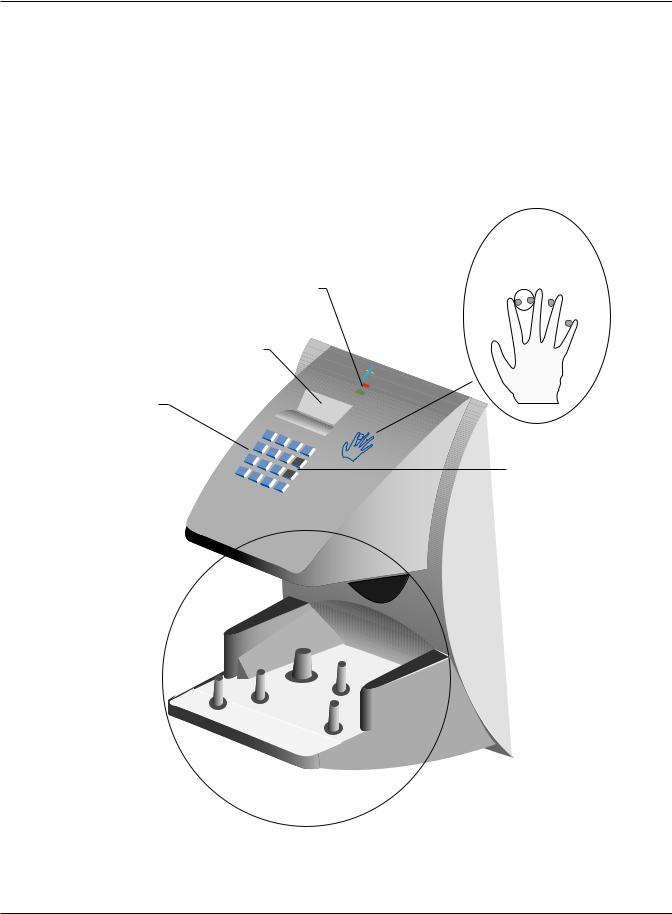
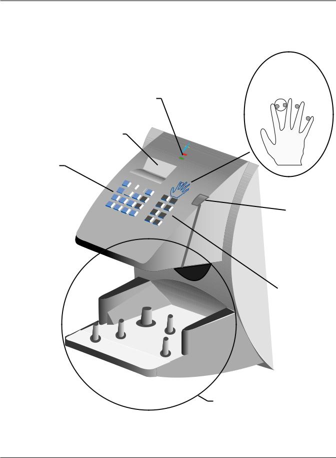
The HandPunch is a time and attendance terminal designed for use with time and attendance software. Refer to “Figure 1-1” on page 5 and “Figure 1-2” on page 6 when reviewing the information in this section.
The HandPunch has an integrated keypad for ID entry and reader programming. The HandPunch 3000 has two function keys (F1 and F2 – see Figure 1-1). The HandPunch 4000 has ten function keys (F1 through F10 – see Figure 1-2). These function keys can be programmed to collect data or to activate auxiliary outputs. The CLEAR and ENTER keys assist in data entry and programming.
1.The Platen is the flat surface at the base of the HandPunch (see Figure 1-1). This is where users place their hands for enrollment and verification. It has guide pins to assist positioning the fingers during use.
4
HandPunch 3000/4000 Manual
Four different features assist the user with hand placement and read verification.
1.A light emitting diode (LED) hand placement display on the HandPunch’s top panel assists users with hand placement on the platen.
2.A liquid crystal display (LCD) shows operational data and programming menus.
3.“Red light/Green light” verification LEDs quickly inform users if their verification attempts were rejected or accepted.
4.An internal beeper provides audible feedback during keypad data entry and user verification.
HAND
PLACEMENT
DISPLAY
VERIFICATION
LIGHTS
LCD DISPLAY
Recognition |
Systems |
|
|
|
Inc. |
NUMERICAL
KEYPAD
|
|
|
|
1 |
|
2 |
|
|
|
|
|
|
|
|
|
|
4 |
|
|
3 |
|
|
|
|
5 |
Clear |
|
|
|
|
|
|
||
|
|
|
|
|
6 |
|
|
7 |
|
|
|
|
|
|
|
|
8 |
|
F1 |
|
|
|
|
|
|
||
* |
|
|
|
|
9 |
|
|
|
|
|
|
||
No |
|
0 |
|
|
|
F2 |
|
|
|
# |
|
||
|
|
|
|
|
|
|
|
|
|
|
Yes |
|
Enter |
|
|
|
|
|
|
FUNCTION
KEYS
 PLATEN AND GUIDE PINS
Figure 1-1: The HandPunch 3000
5
Introduction
VERIFICATION
LIGHTS
LCD DISPLAY
NUMERICAL
KEYPAD
4


Recognition |
Systems |
|
|
|
Inc. |
F3
F7
F5
F9
HAND
PLACEMENT
DISPLAY
BAR CODE
CARD
READER
FUNCTION
KEYS
PLATEN AND GUIDE PINS
: The HandPunch 4000
6
|
HandPunch 3000/4000 Manual |
|
|
Specifications |
|
|
Table 1: Specifications |
|
|
Size: |
8.85 inches wide by 11.65 inches high by 8.55 inches deep. |
|
|
|
223 cm wide by 29.6 cm high by 21.7 cm deep. |
|
|
Power: |
12 to 24 VDC or 12 to 24 VAC 50-60 Hz, 7 watts |
|
|
Weight: |
6 lbs (2.7 kg) – 7 lbs (3.2 kg) with optional backup battery |
|
|
Wiring: |
2 twisted-pair, shielded, AWG 22 or larger (such as Belden 82732) |
|
|
Temperature: |
-10°C to +60°C – non-operating/storage (14°F to 140°F) |
|
5°C to 40°C – operating (40°F to 110°F) |
|
|
Relative Humidity Non- |
5% to 95% – non-operating/storage (non-condensing) |
Condensing: |
20% to 80% – operating |
|
|
Verification Time: |
1 second or less |
|
|
Memory Retention: |
5 years using a standard internal lithium battery |
|
|
Transaction Buffer: |
HP-3000 – 5,120 transactions |
|
HP-4000 – 7,680 transactions |
ID Number Length: |
1 to 10 digits |
|
|
Baud Rate: |
300 to 28.8 K bps |
|
|
Communications: |
RS-232, RS-422, optional Modem, optional Ethernet |
|
|
User Capacity: |
HP-3000 – 512 users expandable to 40,xxx |
|
HP-4000 – 530 users expandable to 5,xxx |
|
|
Message Capacity: |
HP-4000 – 550 exandable to 3520 (not available with the HP-3000) |
|
|
Function Keys: |
HP-3000 – 2 user definable, HP-4000 – 10 user definable |
|
|
Card Reader Input: |
Proximity, Wiegand, Magnetic Stripe, Bar Code |
|
(5 VDC provided by HandPunch unit) |
|
|
Door Controls: |
Lock output, Request to Exit input, Door Switch input |
|
(open collector, 5 VDC present, sinks to ground, 100 mA max) |
|
|
Alarm Monitoring: |
Tamper, Door Forced |
|
|
Event Monitoring: |
There are a variety of monitoring options including events such as: |
|
Invalid ID, Time Zone Violation, ID Refused, Try Again, Power |
|
Failure |
Time Zones: |
62 total: 2 fixed, 60 programmable |
|
|
|
|
|
7 |

Introduction
|
Table 1: Specifications |
|
|
Time Schedules: |
HP-4000 – 3 definable time schedules per user |
Auxiliary Inputs: |
2 (open collector, 5 VDC present, sinks to ground, 100 mA max) |
Auxiliary Outputs: |
up to 3 user definable |
|
(open collector, 5 VDC present, sinks to ground, 100 mA max) |
Options |
HandPunch units have the following options available. |
||
|
|||
|
• |
Backup Battery Support |
See Technical Note 70200-0012 – Rev. D |
|
• |
Modem Communication |
See Technical Note 70200-0013 – Rev. D |
|
• |
Ethernet Communication |
See Technical Note 70200-0014 – Rev. D |
Recommended European Power Supply1:
Ault, Inc.
7300 Boone Ave. North Minneapolis, MN 55428 USA
PH: 612-493-1900 E-mail: info@ault.com
Part number: D48-121000-A040G
230 VAC Input, 12 VDC @ 1Amp output (unregulated)
Ault style #41 connector (barrel plug)
approved
recyclable
1.Not evaluated by UL for UL 294 installations.
8
HandPunch 3000/4000 Manual
UL
Compliance
The HP-3000 and HP-4000 meet UL compliance requirements for UL 294 Access Control Systems under this condition:
1.The HandPunch is configured at the factory with a Wiegand output that enables the HandPunch to communicate with an access control panel. The access control panel controls the locking and unlocking of the door. The panel must reside on the secure side of the facility.
9

Introduction
This page is intentionally blank.
10

HandPunch 3000/4000 Manual
Planning an Installation
Site Before you begin installation, check the site blueprints, riser diagrams, and Preparation specifications for important information about the HandPunch’s location and
other systems that will connect to the HandPunch. Look for any existing wall preparations and wiring that other contractors may have installed for the
HandPunch. A wire routing layout diagram (see “Figure 3-2” on page 25) is provided to assist in planning.
HandPunch The recommended height for the HandPunch platen is 40 inches (102 cm) Placement from the finished floor. The HandPunch should be out of the path of pedestrian
and vehicular traffic, and convenient too, but not behind the door it is controlling.
Avoid placing the HandPunch where users must cross the swing path of the door.
The HandPunch should be in an area where it is not exposed to excessive airborne dust, direct sunlight, water, or chemicals.
40 in. (102 cm.)
Figure 2-1: HandPunch Placement Rules
 NOTE For the following sections, Schlage Biometrics does not supply hardware items such as door control relays, door locks, switches, relays, communications or power wiring.
11

Planning An Installation
Wiring
Four basic circuits typically connect to the HandPunch:
•Power Input
•Earth Ground and Shielding
•Networking and Communications
•External Devices
The minimum wire size for these circuits is AWG 22; the maximum wire size is AWG 18. Schlage Biometrics recommends using Belden 82732 or its equivalent when wiring for RS-422 communications.
Power |
The HandPunch uses an internal switching regulator to obtain internal |
Input |
operational power. It accepts input voltages from 12 to 24 VDC or 12 to 24 VAC |
|
at 50 to 60 Hz. The HandPunch comes with a 120 VAC to 13.5 VDC power |
|
supply (Class 2, Model No. P48131000A010G-120 VAC, 60 Hz, 21 W, 13.5 |
|
VDC output @ 1000mA), if need an optional 220 VDC power supply is also |
|
available (this power supply was not evaluated for UL 294). |
|
To power the HandPunch with this power supply, a 120 VAC (or 220 VAC as |
|
applicable) duplex outlet must be within 5 feet of the HandPunch. The power |
|
supply has a 6-foot cable to provide a comfortable reach between power |
|
outlet and HandPunch. The barrel jack at the of the power supply’s cable is |
|
connected to J12 on the HandPunch PCB. |
NOTE |
J6 terminal 1 and the center pin of power jack J12 are connected together. |
|
J6 terminal 2 and the sleeve of power jack J12 are connected together. |
NOTE |
Neither terminal 1 or terminal 2 is connected to the HandPunch ground. |
NOTE |
Do not connect a HandPunch’s power supply to a switched duplex outlet. The |
|
HandPunch must have a constant source of power for proper operation. |
Battery |
The HandPunch uses an internal switching regulator to obtain internal |
Backup |
operational power. It accepts input voltages from 12 to 24 VDC or 12 to 24 |
|
VAC at 50 to 60 Hz. An optional power-fail protection circuit board can be |
|
attached to the main circuit board to provide and control battery backup. |
|
The design of the internal power supply is such that any range of the above |
|
input voltages may be used and still provide proper battery charge voltage |
|
and battery backup operation. Switch-over to battery power is automatic and |
|
occurs when the input voltage falls to approximately 10.5 volts. At that time the |
|
internal battery charger is disabled to save power and uninterrupted operation |
|
continues on battery power. |
12

HandPunch 3000/4000 Manual
Earth
Ground and Shielding
When input power is restored, the HandPunch switches off of battery operation and the battery charger is re-enabled to recharge the battery. Battery charge voltage is set at approximately 13.65 volts, and battery charge current is limited to approximately 50 mA. A fully discharged battery requires approximately 12 hours of charge to fully recover.
Additional options installed and specific configurations within the HandPunch make it difficult to predict precisely how long battery support will last, but in general two hours of battery operation can be expected. While operating on battery backup due to loss of main input power, the battery output voltage
is constantly monitored by internal circuitry. If the battery voltage reaches approximately 9.5 volts the HandPunch automatically shuts down. This is done to prevent full exhaustion of the battery. A yellow indicator on the top panel illuminates to indicate that the HandPunch is running off of battery power. This indicator extinguishes when main input power is restored.
Shunt J7 which is located to the left of TS3 see “Figure 4-1” on page 31 enables or disables battery operation on those HandPunchs equipped with optional battery backup. If a HandPunch does not have the optional battery backup package installed, J7 is not used. On HandPunchs equipped with the battery backup option, J7 allows service personnel a mechanism for disabling battery backup operation before removal of main input power. To fully power down a
HandPunch equipped with battery backup, remove or reposition shunt J7 so that the two pins protruding up from the main logic board are not connected to each other. This effectively opens the circuit, removing the battery from any internal circuitry. Main input power can then be removed and the HandPunch will fully shut down. Once the HandPunch has fully shut down, shunt J7 may be reinstalled. The design of the power supply is such that main input power must be reapplied to re-enable the battery protection mechanism. If shunt J7 is not properly installed, the internal backup battery will not be charged, and in the event of a main input power loss, the HandPunch will shut down.
The HandPunch with the battery backup option uses a 12 volt 800 ma/hour sealed lead acid battery to provide backup battery power. This battery is located immediately inside the rear panel of the HandPunch and plugs into jack J4 on the keypad control circuit board located in the top of the chassis.
Schlage Biometrics recommends that all HandPunchs be grounded with a solid, reliable earth ground connection. This connection establishes a common ground return point used to protect internal semiconductor devices from ElectroStatic Discharge (ESD) and from external signal line transients. It also provides a common signal level reference point between externally networked HandPunchs. Schlage Biometrics recommends that the earth ground source be identified by a qualified electrician familiar with electrical codes as well as wiring and grounding techniques.
13
Planning An Installation
This is an extremely important and often overlooked aspect of hard-wired serial communication systems. If the sending and receiving stations do not agree on the ground reference for the signal voltages, communication errors or a total inability to communicate may be observed. If the voltages are very different, it is even possible to damage the units.
The subject of grounding can be complicated, and the full circuit of a system, including power supplies and often even the building line power wiring, must be understood. It is strongly recommended that a qualified electrician or electrical engineer familiar with this subject be consulted when designing the wiring of an HGU network installation. Always adhere to any applicable electrical codes for your area. Schlage Biometrics is not responsible for damage done to units due to improper wiring.
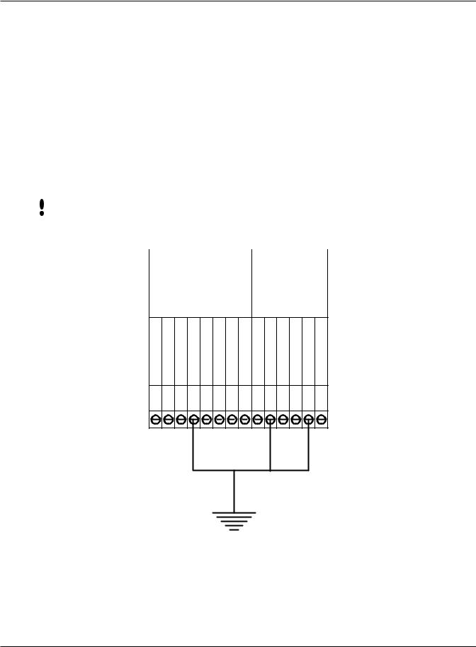
NOTE |
Use any one of the following ground terminals to make the earth ground |
||||||||||||||||
|
connection: 4, 10, or 13. Do NOT use terminal 2 to establish the earth ground |
||||||||||||||||
|
connection; terminal 2 is not directly connected to ground. |
||||||||||||||||
|
|
|
|
|
|
|
|
|
|
|
|
|
|
|
|
|
|
|
|
1 |
2 |
3 |
|
4 |
5 |
6 |
7 |
8 |
9 |
10 |
11 |
12 |
13 |
14 |
|
|
|
|
CARD |
|
OUTPUTS |
|
SWITCH |
||||||||||
|
|
|
READER |
|
|||||||||||||
|
|
|
|
INPUTS |
|||||||||||||
|
|
|
INPUT |
|
|
|
|
|
|||||||||
|
|
|
|
|
|
|
|
|
|
|
|
|
|
||||
OUTPUTVDC+5 |
DATA/D0 |
CLOCK/D1 |
GROUND |
CLOCKORLOCK |
DATAORBELL |
1AUXOUT |
2AUXOUT |
SWITCHREX |
2INAUX GROUND 1INAUX SWITCHDOOR GROUND |
1 |
2 |
3 |
4 |
5 |
6 |
7 |
8 |
9 |
10 11 12 13 14 |
EARTH GROUND ONNECTION PIN
Figure 2-2: Earth Ground Connection Terminals
14

HandPunch 3000/4000 Manual
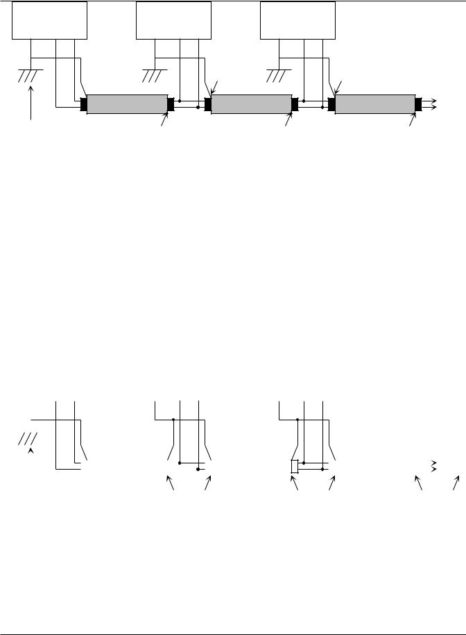
There are two standard methods for providing earth grounding to HandPunch units:
•earth grounding all units (see Figure 2-3)
•carrying an earth ground to each unit (see Figure 2-4)
Earth ground all units when there is a good earth ground source near each unit and/or when there are very long cable runs between units.
Carry an earth ground to each unit when there are no earth grounds Earth Ground convenient to the unit and the unit’s power supply is floating.
All Units
One method of establishing a ground reference is to connect each unit’s main board ground to earth ground. Earth ground is found on the third pin on standard AC line sockets (in the United States, this is the round one in the middle). If the building wiring is functioning correctly, this should be a lowimpedance path to a true ground, which then serves as a common reference point for the units.
If this method of grounding the units is used, it is not necessary to connect the units in the network together with a ground line in the communication cable. Indeed, doing so could create ground loops—large-area loops which provide a good coupling to external magnetic fields—which may actually compound communication problems. If a magnetic field, such as that from a lightning strike, induces a voltage in the ground loop, it is possible for large currents
to flow around the loop, which can raise the ground potential of some units relative to others. When the shield or the cable is connected to any ground in this configuration, it should be connected only at one end to prevent the formation of ground loops.
For systems with multiple units on a network, there will be a series of cables daisy-chained between the units, and the shield of each leg of the network should be connected to ground at only one end. It does not matter which end.
An example of this method of grounding is shown in Figure 2-3.
15
Planning An Installation
Master
GND T+ T-
Remote 1 |
|
Remote 2 |
|
||
GND |
R+ |
R- |
GND |
R+ |
R- |
|
|
Connect the |
|
|
Connect the |
|
|
Cable Shield to |
|
|
Cable Shield to |
|
|
Remote 1's |
|
|
Remote 2's |
|
|
Ground |
|
|
Ground |
|
|
|
|
|
To Next |
|
|
|
|
|
Remote |
Connect the Cable |
Do Not Connect |
Do Not Connect |
Do Not Connect |
Shield to the |
the Cable Shield |
the Cable Shield |
the Cable Shield |
Master's Ground |
at this End |
at this End |
at this End |
Carry a Ground Line to Each Unit
Figure 2-3: Communication Shielding with All Units Earth Grounded
All units are connected to the same earth ground. Each shield ground is connected to only one unit, then interrupted to prevent the formation of ground loops. Two sets of lines are wired as shown in Figure 2-3. It does not matter significantly which unit’s GND is used for a particular shield, as long as the path is broken from unit to unit.
The second method of establishing a ground reference in a system with floating power supplies is to use the ground line in the RS-422 cable to establish a common reference voltage for the communication signals. This line should be connected to the negative power terminal on the data converter or the ground line in the RS-232 port from the host PC system. It should then be carried to one of the ground terminals on the back of each unit in the network.
An example of this method of grounding is shown in Figure 2-4.
|
|
Master |
|
Remote |
1 |
|
Remote |
2 |
|
|
GND T+ T- |
|
GND R+ |
R- |
|
GND R+ |
R- |
||
|
|
|
|
|
|
|
|
|
|
|
|
|
|
|
|
|
|
|
|
|
|
|
|
|
|
|
|
|
|
|
|
|
|
|
|
|
|
To Next |
|
|
|
|
|
|
|
|
|
|
|
|
|
|
|
|
|
||
|
|
|
|
|
|
|
|
|
|
|
|
|
|
|
|
|
|
Remote |
|
|
|
|
|
|
|
|
|
|
|
|
|
|
|
|
|
|
|
|
|
|
|
|
|
|
|
|
|
|
|
|
|
|
|
|
|
|
Connect the Cable |
Connect Both Shields |
Connect Both Shields |
Connect Shield |
|||||||||||||||
Shield to the |
||||||||||||||||||
Master's Ground |
to Remote 1 Ground |
to Remote 2 Ground |
to Next Remote |
|||||||||||||||
: Communication Shielding Carrying a Single Ground to Each Unit
If no earth ground is available at the units, this is the only possible method of connecting the grounds. Even if an earth ground is available, depending on the building’s power wiring and other environmental issues, this method may be superior to the previous one, since it establishes the ground of each unit independently of the building power lines. Local variations in grounds between buildings, or from one point to another in a very large building, (perhaps due to
16

HandPunch 3000/4000 Manual
elevator motors or other large-current drawing machines) will have no effect on the communication network if this configuration is used.
However, the power supplies must be truly floating, with no hidden paths back to the high-voltage side of the transformers, or to earth ground. Since this
is difficult to achieve (there is always some parasitic capacitance between the primary and secondary in any transformer), this method may be more susceptible to high-frequency transients in the high-voltage side of the power lines than the earth-grounded method.
The master unit’s ground establishes the ground for the entire system. The main board ground points are connected to the shield ground at each unit, but are not connected to earth ground. The ground point on the master can be the data converter power supply negative terminal, or the GND pin on the
RS-232 cable. If the master is an HGU, its main board ground can be used.
This configuration should only be used if the power supplies to the units are truly floating, otherwise ground loops will be created, and differences in local grounds may cause large currents to flow through the cable shield.
17

Planning An Installation
Communications
HandPunch |
HandPunch/host computer communications can be configured in one of three |
to Host |
ways: |
Computer |
• via a direct RS-232 connection |
Connection |
|
|
• via a direct RS-422 connection using a data converter |
|
• via an optional Ethernet network connection (one HandPunch terminal |
|
must have the Ethernet communication option installed) |
|
• via an optional Modem connection (one HandPunch terminal must have |
|
the Modem communication option installed) |
RS-232 Host
Computer
Connection
 NOTE
NOTE
RS-422 Host
Computer
Connection
A direct HandPunch connection to a host computer can be made through an
4-conductor cable in an RS-232 serial configuration. A 6’ or 50’ cable may be purchased through Schlage Biometrics or a wiring diagram for the RS-232 to host computer connection is found on “Table 4” on page 33.
If you make the RS-232 to host computer connection you cannot use the serial printer option (see page 21).
A direct HandPunch network connection to a host computer can be made through a shielded, 4-conductor cable in a full-duplex RS-422 configuration.
An RJ-11 jack must be installed within 6 feet of the host computer. Position the RJ-11 jack using the template provided in this manual (see “Figure 3-2” on page 25). The HandPunch RS-422 network is connected to this jack.
A data converter (Schlage Biometrics P/N: DC-102) is required to connect the host computer to the RS-422 HandPunch network. The DC-102 is connected to an available RS-232 serial port on the computer. Then connect the DC-102 to the RJ-11 jack using the 8 foot cable provided with the DC-102. A wiring diagram for the RS-422 to host computer connection is found on page 31.
A HandPunch communication network is then connected, unit-to-unit, via an
RS-422 “daisy-chain” network. A network RJ-11 jack is installed on or in the wall behind each terminal. Each RJ-11 jack is then interconnected in daisychain fashion using two, twisted-pair, AWG22 wires (Schlage Biometrics recommends using Belden No. 82723 cable). The daisy-chain network can extend up to 4,000 feet in length, and can have up to 31 HandPunch terminals connected to it.
Connect the HandPunch terminal to the RJ-11 jack using the short silver cable provided with the terminal.
18
HandPunch 3000/4000 Manual
NOTE When wiring the RS-422 daisy-chain network, do not wire HandPunch terminals in a “star” network (a network where a number of units are all
connected to the network at one, central location – see Figure 2-5).
|
|
|
|
|
|
|
|
|
|
|
|
|
Hand |
|
Hand |
|
|
|
|
|
|
|
|
|
|
|
|
|
|
||
|
|
|
|
|
|
|
|
|
|
|
|
|
Punch |
|
Punch |
|
|
|
|
|
|
|
|
|
|
|
|
|
|
|
|
|
Hand |
|
Hand |
|
Hand |
|
Hand |
|
|
|
|
||||
|
Punch |
|
Punch |
|
Punch |
|
Punch |
|
|
|
|
||||
|
|
|
|
|
Hand |
|
Hand |
||||||||
|
|
|
|
|
|
|
|
|
|
|
|
|
|
||
|
|
|
|
|
|
|
|
|
|
|
|
||||
|
|
|
Daisy Chain - OK |
|
|
|
Punch |
|
Punch |
||||||
|
|
|
|
|
|
|
|
|
|||||||
|
Star - Not Supported |
|
Figure 2-5: Daisy-Chain Versus Star Network Communication Connections |
Ethernet Host |
The HandPunch is available with an optional, internal Ethernet |
Computer |
communications module for TCP/IP communications between the HandPunch |
Connection |
network and the host computer. When connecting via an Ethernet connection, |
|
one HandPunch terminal must be configured with this Ethernet option. This |
|
terminal will communicate with the host computer. |
|
To make the Ethernet connection, the Ethernet wiring must conform to |
|
10BaseT standards. An Ethernet RJ-45 jack must be installed on or in the wall |
|
behind the Ethernet HandPunch terminal. Position the jack location using the |
|
template provided in this manual (see “Figure 3-2” on page 25). The cable from |
|
the jack to the HandPunch is not provided with the Ethernet option. A wiring |
|
diagram for the Ethernet to host computer connection is found on page 39. |
|
IP Address and Gateway and Subnet Mask information is entered at the |
|
HandPunch using the Set Serial command (see page 59). |
Modem Host |
The HandPunch is also available with an optional modem module for |
Computer |
telephone line communications between the HandPunch network and the |
Connection |
host computer. When connecting via modem, one HandPunch terminal must |
|
be configured with the modem option. This terminal will communicate with the |
|
host computer. |
|
To make the modem connection, a telephone jack must be installed on or |
|
in the wall behind the modem HandPunch terminal. Position the RJ-11 jack |
|
location using the template provided in this manual (see “Figure 3-2” on page |
|
25). The short black cable provided with the modem HandPunch connects the |
|
terminal to the telephone jack. A wiring diagram for a modem to host computer |
|
|
|
19 |

Planning An Installation
connection is found on page 40.
External Devices
The HandPunch can control external devices such as:
•Bell
•Door Lock
•Request to Exit, Door Switch, and Auxiliary Inputs
•Auxiliary Outputs
•External Card Reader
•Serial Printer
The HandPunch requires the use of an external DC power supply to operate other controls or relays. The power supply can be of a different voltage than that used to power the HandPunch. The bell, door lock, and auxiliary outputs switch to ground when activated. For these devices, one pole of a control relay is connected to the PLUS side of the power supply, and the other pole connects to the output connection (switched minus) on the HandPunch. The negative pole on the external power supply must connect to a negative
(ground) connection on the HandPunch to complete the circuit. The current draw of the relay or external device must not exceed 0.1A.
Wiring for these devices should enter the HandPunch through the opening in the center of the wall plate or through the conduit opening at the right side of the HandPunch.
The external DC power supplies and relays needed to operate external  NOTE devices such as bells or door locks are NOT provided by Schlage Biometrics.
You must provide these power supplies.
Bell
Door Lock
The bell control circuit switches direct current to ground when actuated. The bell must receive its power from an external power supply through the contacts of a bell control relay. Refer to the Bell Output Wiring Diagram on page 34.
The door lock control output of the HandPunch switches to ground upon verification (unless programmed to send card data to a third-party control panel). As the output is limited to 0.1A, a lock control relay must be used.
Refer to the Lock Output Wiring Diagram on page 35 for lock output wiring connections. The relay and lock must receive power from an external power supply.
20

HandPunch 3000/4000 Manual
Request to Exit, Door Switch, and Auxiliary Inputs
Auxiliary
Outputs
External
Card Reader
 NOTE
NOTE
Serial Printer
The HandPunch terminal has four inputs. Refer to the Inputs Wiring Diagram on page 36.
•Request to Exit
•Door Switch
•Two Auxiliary Inputs
A Request to Exit switch (REX) on the secure side of a controlled door will activate the lock output. When the REX switch is pressed, the door unlocks for a specified time. The REX switch must be a momentary contact, normally open switch rated greater than 0.5 mA, 5 VDC circuit.
A Door Switch monitors door status – open or closed. The door switch must be a normally closed switch rated greater than 0.5 mA, 5 VDC circuit.
Auxiliary Input requirements vary, depending upon the type of input device, but the input device should be rated greater than 0.5 mA, 5 VDC circuit.
The HandPunch allows for the connection of up to three auxiliary output devices. Refer to the Outputs Wiring Diagram on page 35.
You can connect an external card reader (such as a magnetic stripe, bar code, or proximity reader) to a HandPunch. This external card reader provides a secondary level of user identification.
The HandPunch may require special format programming to be able to read these external card reader formats. Contact your dealer for information.
The connection to an external card reader is made through TS-3 on the HandPunch. Refer to the External Card Reader Wiring Diagram on page 37.
You can connect a serial printer to a HandPunch. A serial printer connected to the HandPunch prints punches as they occur. Schlage Biometrics does not supply serial printers. The connection to a serial printer is made through J4, the 4 pin connector on the HandPunch. Refer to the Serial Printer Connection
Diagram on page 41. Refer to the Printer String Information Application Note (available from Schlage Biometrics) for detailed information on connecting a serial printer to a HandPunch.
NOTE |
If you use the serial printer option you cannot use the RS-232 HandPunch |
|
network to host computer option (see page 18). |
21

Planning An Installation
This page is intentionally blank.
22
HandPunch 3000/4000 Manual
Mechanical Installation
Wall Plate
Installation
 NOTE
NOTE
Select an installation location based on the guidelines provided in the Planning an Installation section beginning on page 11.
For the following instructions protect the HandPunch from the dust and debris generated during the wall plate installation process.
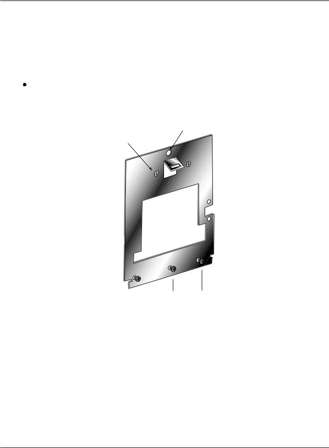
1.Remove the wall plate from the packing carton. Refer to Figure 3-1 for all wall plate references in the following section.
LEVELING HOLE
2 UPPER SCREWS
SURFACE
CONDUIT
ENTRY
 3 LOWER SCREWS
Figure 3-1: Wall Plate
2.Measure and mark a point 42 1/2 inches (123 cm) from the surface of the finished floor. This point will correspond to where the top-center point of the
HandPunch should be mounted.
3.For a hollow wall, drive a small nail into the wll at the mark and hang the wall plate from the leveling hole located near the top of the wall plate.
4.For a solid wall, hold teh wall plate against the wall, centering the leveling hole over the mark in the wall.
23

Networking and Communications
5.Align a bubble level with the top edge of the wall plate and gently rotate the wall plate until the bubble level shows that the totp edge of the wall plate is level.
6.Secure the plate to the wall using heavy masking tape.
7.Using the wall plate as a template, mark the locations of teh two upper screw holes and the three lower screw holes.
8.For a concealed wiring connection, trace the outline of the open area in the center of the wall plate. Identify and mark a 1/2 inch hole through which the
HandPunch’s wiring will be mounted.
9.For a surface conduit wiring connection, mark the two conduit clamp holes at the right side of the wall plate.
10.Remove the wall plate, masking tape, and the nail (if used).
Mounting the 1. For a hollow wall, use the provided hardware to mount the wall plate. Use Wall Plate the two auger style fasteners for teh upper two mounting holes. Use the
toggle bolts for the three lower mounting holes.
2.For a solid wall, use expansion bolts to mount the wall plate. For all five mounting holes, drill a 1/4 inch diameter hole, 1/4 of an inch deeper than the length of the expansion anchor.
Routing the 1. For a concealed wiring connection, drill a 1/2 inch hole in a convenient Wiring location within the open area of the wall plate. Pull the wiring to enter the
HandPunch through this hole in the open area.
2.For a surface conduit wiring connection, drill a 1/4 inch diameter hole, 1/4 of an inch deeper than the length of the expansion anchor for each of the two conduit clamp holes. Route 1/2 inch conduit to the HandPunch, ending the conduit between the two conduit clamp holes. Pull the wiring to enter the HandPunch through the conduit.
24
HandPunch 3000/4000 Manual
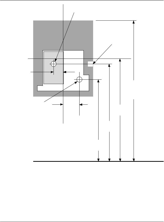
|
WIRE ENTRY POINT |
||
|
FOR RJ-11 JUNCTION BOX |
||
Wall Plate |
|
SURFACE |
|
|
|
||
|
|
CONDUIT |
|
|
|
ENTRY POINT |
|
|
|
C |
|
|
|
L |
|
1.25" |
|
|
|
(3 cm) |
|
|
|
|
|
50" Reference |
|
|
|
(127 cm) |
|
|
|
to Top of |
|
|
|
Wall Plate |
|
WIRE ENTRY POINT |
2" |
|
|
(5 cm) |
42.75" |
||
FOR SURFACE |
|||
|
(108.6 cm) |
||
RJ-11 BOX |
|
|
|
|
C |
42.5" |
|
|
(108 cm) |
||
|
L HandPunch |
||
|
|
40.75" |
|
|
|
(103 cm) |
|
Finished Floor
Figure 3-2: HandPunch Wire Routing Layout
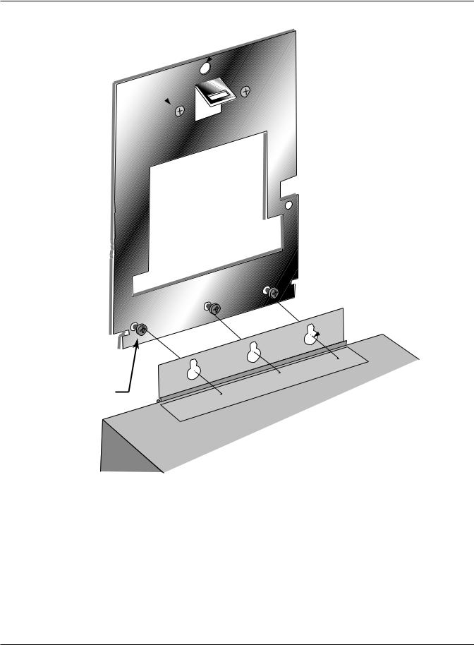
Attaching the 1. Remove the HandPunch from its carton.
HandPunch 2. Align the sleeves of the back plate with the pins of the wall plate and slide the HandPunch to the left as shown in “Figure 3-3” on page 26.
25
Networking and Communications
HOLE
2 UPPER SCREWS
 SURFACE
CONDUIT
ENTRY
KEYHOLE
HOLES
3 LOWER MOUNTING SCREWS
REAR OF TERMINAL
: Attaching the HandPunch to the Wall Plate
3. The Hand Punch is now ready for its wiring connections.
26

HandPunch 3000/4000 Manual
Networking and Communications
Stand-alone
HandReader
HandReader networking and communications can be configured in one of five ways:
•as a stand-alone HandReader
•as a master or remote HandReader in a HandReader network
•as a remote HandReader in a HandReader network connected to a host
PC
•as a remote network connected via optional Modem to host PC
•as a remote network connected via optional Ethernet to host PC
When installed as a stand-alone access control system there is no communication wiring to other HandReaders or to a host computer. Power input and control output wiring are all that are required. An RS-232 serial printer output is available for event logging (refer to the Printer section on 29). Schlage Biometrics highly recommends using Backhand™ software to backup template information stored in the HandReader.
Master or Remote HandReader in a HandReader Network
Remote HandReader in a HandReader Network Connected to a Host PC
Multiple HandReaders can be linked together in a HandReader network.
•Up to 32 HandReaders can be linked together on a 2-wire RS-485 or 4-wire RS-422 network (see Figure 3-1).
•Two twisted-pair, shielded, AWG 22 (or larger) wire should be used
(Schlage Biometrics recommends Belden 82732 or its equivalent).
•The wiring must be a “daisy-chain” network from HandReader to
HandReader and must not exceed 4,000 feet (1220 meters) in total length.
The master/remote network requires user enrollment at the “master”
HandReader. The master HandReader distributes hand template data with ID numbrs and time restrictions (if any) to the other HandReaders in the network.
Users removed at the master HandReader are automatically removed from the remote readers. A printer connected to the master HandReader will report transactions from all Handreaders on the network.
Multiple HandReaders can be linked to a presonal computer (PC) for an integrated access control network. Real time monitoring of door status and a variety of alarm types can be done with Schlage Biometrics’ HandNet for Windows™ (Schlage Biometrics model number HN-300) software. To run HandNet for Windows™, the computer must be PC compatible, using a Pentium™-166 or faster microprocessor and it must have a CD-ROM.
•The HandNet software can monitor over 1,000 HandReaders simultaneously.
27

Networking and Communications
Remote HandReader Connected to a Host PC via Optional Modem
•An unlimited number of sites can be created with up to 32 HandReaders per site.
•The HandReaders report all transactions to the PC. The HandNet software records all transactions and displays a variety of reports generated from this information.
•Template management is handled automatically.
•Users may enroll at any HandReader in the system. The PC collects the data and distributes it to other HandReaders in the network.
•Access may be restricted by time and by HandReader via HandNet’s access profiles and by the use of time zones.
Typically, HandReader networks link to a PC using an RS-422 connection. These networks have the following requirements:
•Two twisted pair, shielded, AWG 22 wire or larger should be used (Schlage
Biometrics recommends Belden No. 82723 or equivalent cable).
•HandReaders must be wired together in a “daisy-chain” network from
HandReader to HandReader and then to the host PC. The total length of teh wiring must not exceed 4,000 feet per network.
•The network requires an RS-422 to RS-232 converter (Schlage Biometrics
P/N DC-102) at the PC.
Schlage Biometrics’ optional HandNet for Windows™ software allows programming of most of the remote HandReader setups from the computer. However, each HandReader on the network requires the setting of an address.
HandReader addresses may be repeated, but only on different sites. Display language, date format changes, and the communication mode must also be set at the HandReader.
An optional internal “answer only” 14.4 bps modem is available for
HandReaders. This modem is designed for operation with United States phone systems. Site wiring should conform to standard telephone wiring standards and terminate at teh HandReader with a standard RJ-11 modular phone
jack. Each HandReader with a modem includes a XXXX cable for the final connection between the phone jack and the HandReader modem. Modem HandReaders may be networked with up to 31 non-modem HandReaders using RS-422 wiring. Refer to the Modem application note (available from Schlage Biometrics) for detailed information.
28
 Loading...