


 Loading...
 100
100 


Reference Guide
Regulatory models T102, T104
5B.13201.001

Table of contents
Introduction.................. |
3 |
Projector features........................... |
3 |
Shipping contents .......................... |
4 |
Projector exterior view ................... |
5 |
Controls and functions ................... |
6 |
Positioning your |
|
projector ....................... |
9 |
Choosing a location ....................... |
9 |
Obtaining a preferred projected |
|
image size.................................... |
10 |
Connection................. |
13 |
Connecting a computer or |
|
monitor ......................................... |
14 |
Connecting video source |
|
devices......................................... |
16 |
Operation.................... |
20 |
Starting up the projector............... |
20 |
Using the menus .......................... |
21 |
Utilizing the password function .... |
22 |
Switching input signal .................. |
24 |
Adjusting the projected image...... |
25 |
Magnifying and searching for |
|
details........................................... |
27 |
Selecting the aspect ratio............. |
27 |
Optimizing the image ................... |
29 |
Setting the presentation timer ...... |
33 |
Hiding the image .......................... |
34 |
Locking control keys .................... |
34 |
Freezing the image ...................... |
35 |
Operating in a high altitude |
|
environment ................................. |
35 |
Adjusting the sound ..................... |
35 |
Personalizing the projector menu |
|
display.......................................... |
36 |
Shutting down the projector ......... |
36 |
Menu operation............................ |
37 |
Maintenance............... |
44 |
Care of the projector .................... |
44 |
Lamp information ......................... |
45 |
Troubleshooting ........ |
51 |
Specifications ............ |
52 |
Projector specifications................ |
52 |
Dimensions .................................. |
53 |
Timing chart ................................. |
53 |
Copyright |
|
information................. |
55 |
2 Table of contents

Introduction
Projector features
The projector integrates high-performance optical engine projection and a userfriendly design to deliver high reliability and ease of use.
The projector offers the following features.
•Wall color correction allowing projection on surfaces of several predefined colors
•Quick auto search speeding up the signal detecting process
•Selectable password protected function
•Up to 11 sets of picture modes providing multiple choices for different projection purposes
•3D color management allowing color adjustments to your liking
•Selectable quick cooling function makes the projector cool in a shorter time
•Presentation timer for better control of time during presentations
•One-key auto-adjustment to display the best picture quality
•Digital keystone correction to correct distorted images
•Adjustable color balance control for data/video display
•High brightness projection lamp
•Ability to display 16.7 million colors
•Multi-language On-Screen Display (OSD) menus
•Switchable normal and economic modes to reduce the power consumption
•Component HDTV compatibility (YPbPr)
•High quality manual zoom lens
 • The apparent brightness of the projected image will vary depending on the ambient lighting conditions, selected input signal contrast/brightness settings, and is directly proportional to projection distance.
•The lamp brightness will decline over time and may vary within the lamp manufacturer's specifications. This is normal and expected behavior.
Introduction 3
Shipping contents
Carefully unpack and verify that you have all of the items shown below. If any of these items are missing, please contact your place of purchase.
Standard accessories
 The supplied accessories will be suitable for your region, and may differ from those illustrated.
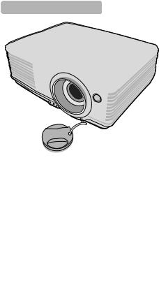
Projector |
Power Cord |
VGA Cable |
|
|
|
|
|
|
|
|
|
|
|
|
|
|
|
|
|
|
|
|
|
|
|
Reference |
Registration |
Quick Start Guide |
Warranty |
|
Safety |
||||
Guide CD |
Card |
Booklet |
|
Booklet |
|||||
|
|
|
|
||||||
Pull the tab before using the remote control.
Remote Control & Battery |
Carry case |
|
|
Optional accessories
1.Ceiling mount, wall mount
2.LiteShow II wireless presentation adaptor
3.Pull down and pull up 4:3 screens
4.Cables and adaptors
5.Replacement lamp
6.Optional remote
7.Projector lock system
4 Introduction
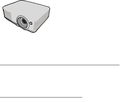
Projector exterior view
Front/upper side
1
2
5
3 |
6 |
|
|
|
7 |
4 |
|
Rear/lower side
8 9 10 11 12 13 14 15
16 |
17 |
18 |
 Warning
1.External control panel (See "Projector and remote
control" on page 6 for details.)
2.Vent (heated air exhaust)
3.Quick-release button
4.Lens cover
5.Focus ring and Zoom ring
6.Front IR remote sensor
7.Projection lens
8.AC power cord inlet
9.RS-232 control port
10.RGB signal output socket
11.RGB (PC)/Component video (YPbPr/YCbCr) signal input socket
12.Video input socket
13.S-Video input socket
14.Audio signal input socket Audio signal output socket
15.Kensington anti-theft lock slot
16.Quick-release foot
17.Lamp cover
18.Rear adjuster foot
•THIS APPARATUS MUST BE GROUNDED.
•When installing the unit, make certain that the associated wall switch or AC power outlet is easily accessible, so that the unit can be quickly disconnected if needed.
Introduction 5

Controls and functions
Projector and remote control
|
|
5 |
8 |
|
|
|
11 |
||
1 |
|
|
||
9 |
14 |
10 |
||
2 |
||||
|
|
|
||
3 |
|
15 |
12 |
|
4 |
|
|||
10 |
|
|
||
5 |
11 |
16 |
13 |
|
6 |
12 |
|
7 |
|
|
11 |
|||
|
|
|
||
7 |
|
|
|
|
8 |
13 |
17 |
|
|
|
|
|
||
|
11 |
|
|
1.Focus ring
Adjusts the focus of the projected image. See "Fine-tuning the image size and clarity" on page 26 for details.
2.Zoom ring
Adjusts the size of the image. See "Fine-tuning the image size and clarity" on page 26 for details.
3.TEMPerature indicator light
Lights up red if the projector's temperature becomes too high. See "Indicators" on page 50 for details.
4.POWER indicator light
Lights up or flashes when the projector is under operation. See "Indicators" on page 50 for details.
5. II POWER
Toggles the projector between standby mode and on. See "Starting up the projector" on page 20 and "Shutting down the projector" on page 36 for details.
6. Left/BLANK
Used to hide the screen picture. See "Hiding the image" on page 34 for details.
7.MODE/ENTER
Selects an available picture setup mode. See "Selecting a picture mode" on page 29 for details.
Enacts the selected On-Screen Display (OSD) menu item.
6 Introduction
8.MENU/EXIT
Turns on the On-Screen Display (OSD) menu. Goes back to previous OSD menu, exits and saves menu settings. See "Using the menus" on page 21 for details.
9.LAMP indicator light
Indicates the status of the lamp. Lights up or flashes when the lamp has developed a problem. See "Indicators" on page 50 for details.
10.AUTO
Automatically determines the best picture timings for the displayed image. See "Auto-adjusting the image" on page 25 for details.
11.Keystone/Arrow keys (  /
/ Up,
Up,
 /
/ Down)
Down)
Manually corrects distorted images resulting from an angled projection. See "Correcting keystone" on page 26 for details.
12. Right/
Activates panel key lock. See "Locking control keys" on page 34 for details. When the On-Screen Display (OSD) menu is activated, the #6, #11, and #12 keys are used as directional arrows to select the desired menu items and to make adjustments. See "Using the menus" on page 21 for details.
13.SOURCE
Displays the source selection bar. See "Switching input signal" on page 24 for details.
14.

 Freeze
Freezes the projected image. See "Freezing the image" on page 35 for details.
15. Left
Left
Selects the desired menu items and makes adjustments. See "Using the menus" on page 21 for details.
16.BLANK
Used to hide the screen picture. See "Hiding the image" on page 34 for details.
17.Digital Zoom keys (+, -)
Magnifies or reduces the projected picture size. See "Magnifying and searching for details" on page 27 for details.
Introduction 7

Remote control effective range
Infra-Red (IR) remote control sensor is located on the front of the projector. The remote control must be held at an angle within 30 degrees perpendicular to the projector's IR remote control sensor to function correctly. The distance between the remote control and the sensor should not exceed 8 meters (~ 26 feet).
Make sure that there are no obstacles between the remote control and the IR sensor on the projector that might obstruct the infra-red beam.
Approx. 15°
Replacing the remote control battery
1.Pull out the battery holder.
 Please follow the illustrated instructions. Push and hold the locking arm while pulling out the battery holder.
2. Insert the new battery (Type: CR-2025) in the holder. Note the positive polarity should face outward.
3.Push the holder into the remote control.
 CAUTION
•Avoid excessive heat and humidity.
•There may be battery damage if the battery is incorrectly replaced.
•Replace only with the same or equivalent type recommended by the battery manufacturer.
•Dispose of the used battery according to the battery manufacturer’s instructions.
•Never throw a battery into a fire. There may be danger of an explosion.
•If the battery is dead or if you will not be using the remote control for a long time, remove the battery to prevent damage to the remote control from possible battery leakage.
8 Introduction
Positioning your projector
Choosing a location
Your room layout or personal preference will dictate which installation location you select. Take into consideration the size and position of your screen, the location of a suitable power outlet, as well as the location and distance between the projector and the rest of your equipment.
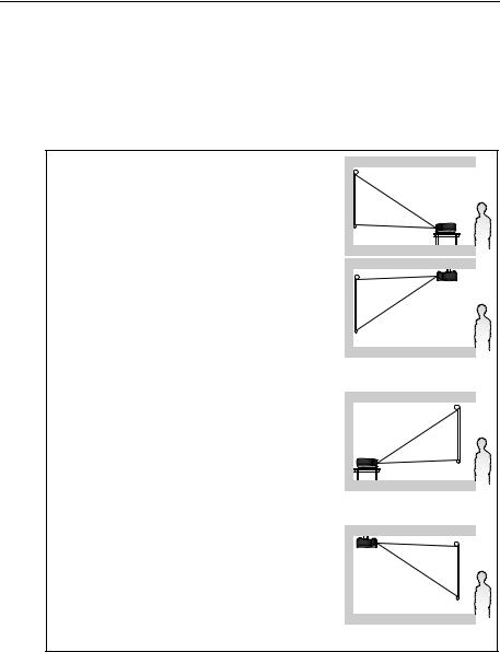
Your projector is designed to be installed in one of four possible installation locations:
1. Front Table
Select this location with the projector placed near the floor in front of the screen. This is the most common way to position the projector for quick setup and portability.
2. Front Ceiling
Select this location with the projector suspended upside-down from the ceiling in front of the screen.
Purchase the InFocus ceiling mount, SP-CEIL- UNIV, from your dealer to mount your projector on
the ceiling.
Set Front Ceiling in the SYSTEM SETUP: Basic >
Projector Position menu after you turn the projector on.
3. Rear Table
Select this location with the projector placed near the floor behind the screen.
Note that a special rear projection screen is
required.
Set Rear Table in the SYSTEM SETUP: Basic >
Projector Position menu after you turn the projector on.
4. Rear Ceiling
Select this location with the projector suspended upside-down from the ceiling behind the screen.
Note that a special rear projection screen and the InFocus ceiling mount, SP-CEIL-UNIV, are required
for this installation location.
Set Rear Ceiling in the SYSTEM SETUP: Basic >
Projector Position menu after you turn the projector on.
Positioning your projector |
9 |

Obtaining a preferred projected image size
The distance from the projector lens to the screen, the zoom setting, and the video format all factor into the resulting projected image size.
4:3 is the native aspect ratio of this projector. To be able to project a complete 16:9 (widescreen) aspect ratio image, the projector can resize and scale a widescreen image to the projector's native aspect width. This will result in a proportionally smaller height equivalent to 75% of the projector's native aspect height.
|
|
|
|
|
|
|
|
|
|
|
|
|
|
|
|
|
|
4:3 aspect image in a 4:3 |
16:9 aspect image scaled to a 4:3 |
||||
aspect display area |
aspect display area |
||||
Thus, a 16:9 aspect image will not utilize 25% of the height of a 4:3 aspect image displayed by this projector. This will be seen as darkened (unlit) bars along the top and bottom (vertical 12.5% height respectively) of the 4:3 projection display area whenever displaying a scaled 16:9 aspect image in the vertical center of the 4:3 projection display area.
The projector should always be placed horizontally level (like flat on a table), and positioned directly perpendicular (90° right-angle square) to the horizontal center of the screen. This prevents image distortion caused by angled projections (or projecting onto angled surfaces).
The modern digital projector does not project directly forward (like older style reel- to-reel film projectors did). Instead, digital projectors are designed to project at a slightly upward angle above the horizontal plane of the projector. This is so that they can be readily placed on a table and will project forward and upwards onto a screen positioned so that the bottom edge of the screen is above the level of the table (and everyone in the room can see the screen).
If the projector is mounted on a ceiling, it must be mounted upside-down so that it projects at a slightly downward angle.
You can see from the diagram on page 12, that this type of projection causes the bottom edge of the projected image to be vertically offset from the horizontal plane of the projector. When ceiling mounted, this refers to the top edge of the projected image.
If the projector is positioned further away from the screen, the projected image size increases, and the vertical offset also increases proportionately.
When determining the position of the screen and projector, you will need to account for both the projected image size and the vertical offset dimension, which are directly proportional to the projection distance.
InFocus has provided a table of 4:3-aspect-ratio screen sizes to assist you in determining the ideal location for your projector. There are two dimensions to consider, the perpendicular horizontal distance from the center of the screen (projection distance), and the vertical offset height of the projector from the horizontal edge of the screen (offset).
10 Positioning your projector
How to determine the position of the projector for a given screen size
1.Select your screen size.
2.Refer to the table and find the closest match to your screen size in the left columns labelled "4:3 screen diagonal". Using this value, look across this row to the right to find the corresponding average distance from screen value in the column labelled "Average". This is the projection distance.
3.On that same row, look across to the right column and make note of the "Vertical offset" value. This will determine the final vertical offset placement of the projector in relation to the edge of the screen.
4.The recommended position for the projector is aligned perpendicular to the
horizontal center of the screen, at the distance from the screen determined in step 2 above, and offset by the value determined in step 3 above.
For example, if you are using a 108-inch screen, the average projection distance is 4320 mm (170”) and with a vertical offset of 82 mm (3.2”).
If you place the projector in a different position (to that recommended), you will have to tilt it down or up to center the image on the screen. In these situations, some image distortion will occur. Use the Keystone function to correct the distortion. See "Correcting keystone" on page 26 for details.
How to determine the recommended screen size for a given distance
This method can be used for situations where you have purchased this projector and would like to know what screen size will fit in your room.
The maximum screen size is limited by the physical space available in your room.
1.Measure the distance between the projector and where you want to position the screen. This is the projection distance.
2.Refer to the table and find the closest match to your measurement in the average distance from screen column labelled "Average". If the min and max values are available on the table, check that your measured distance is between the min and max distances listed on either side of the average distance value.
3.Using this value, look across that row to the left to find the corresponding screen diagonal listed in that row. That is the projected image size of the projector at that projection distance.
4.On that same row, look across to the right column and make note of the "Vertical offset" value. This will determine the final placement of the screen in relation to the horizontal plane of the projector.
For example, if your measured projection distance was 4.5 m (177”), the closest match in the "Average" column is 4320 mm (170”). Looking across this row shows that a 108-inch screen is required.
Positioning your projector |
11 |

Projection dimensions
Refer to "Dimensions" on page 53 for the center of lens dimensions of this projector before calculating the appropriate position.
Maximum zoom |
Minimum zoom |
Screen |
|
|
|
|
|
Center of lens |
|
Vertical offset |
|
|
|
Projection distance |
4:3 screen diagonal |
Recommended projection distance from |
Vertical offset |
||||||||
|
|
|
|
|
screen |
|
|
|
|
|
|
|
|
Min length |
Average |
Max length |
|
|
|||
|
|
|
(with max. |
|
|
(with min. |
|
|
||
|
|
|
zoom) |
|
|
zoom) |
|
|
||
Feet |
Inches |
mm |
mm |
Inches |
mm |
Inches |
mm |
Inches |
mm |
Inches |
4 |
48 |
1219 |
1829 |
72 |
1920 |
76 |
2011 |
79 |
37 |
1.4 |
|
59 |
1500 |
2250 |
89 |
2362 |
93 |
2475 |
97 |
45 |
1.8 |
5 |
60 |
1524 |
2286 |
90 |
2400 |
94 |
2514 |
99 |
46 |
1.8 |
6 |
72 |
1829 |
2743 |
108 |
2880 |
113 |
3017 |
119 |
55 |
2.2 |
|
79 |
2000 |
3000 |
118 |
3150 |
124 |
3300 |
130 |
60 |
2.4 |
7 |
84 |
2134 |
3200 |
126 |
3360 |
132 |
3520 |
139 |
64 |
2.5 |
8 |
96 |
2438 |
3657 |
144 |
3840 |
151 |
4023 |
158 |
73 |
2.9 |
|
98 |
2500 |
3750 |
148 |
3937 |
155 |
4124 |
162 |
75 |
3.0 |
9 |
108 |
2743 |
4114 |
162 |
4320 |
170 |
4526 |
178 |
82 |
3.2 |
|
118 |
3000 |
4499 |
177 |
4724 |
186 |
4949 |
195 |
90 |
3.5 |
10 |
120 |
3048 |
4571 |
180 |
4800 |
189 |
5029 |
198 |
91 |
3.6 |
|
138 |
3500 |
5249 |
207 |
5512 |
217 |
5774 |
227 |
105 |
4.1 |
12 |
144 |
3658 |
5486 |
216 |
5760 |
227 |
6034 |
238 |
110 |
4.3 |
|
157 |
4000 |
5999 |
236 |
6299 |
248 |
6599 |
260 |
120 |
4.7 |
15 |
180 |
4572 |
6857 |
270 |
7200 |
283 |
7543 |
297 |
137 |
5.4 |
|
197 |
5000 |
7499 |
295 |
7874 |
310 |
8249 |
325 |
150 |
5.9 |
18 |
216 |
5486 |
8229 |
324 |
8640 |
340 |
9051 |
356 |
165 |
6.5 |
|
236 |
6000 |
8999 |
354 |
9449 |
372 |
9899 |
390 |
180 |
7.1 |
25 |
300 |
7620 |
11429 |
450 |
12000 |
472 |
12571 |
495 |
229 |
9.0 |
There is 3% tolerance among these numbers due to optical component variations. InFocus recommends that if you intend to permanently install the projector, you should physically test the projection size and distance using the actual projector before you permanently install it, so as to make allowance for this projector's optical characteristics. This will help you determine the exact mounting position so that it best suits your installation location.
12 Positioning your projector

Connection
When connecting a signal source to the projector, be sure to:
1.Turn all equipment off before making any connections.
2.Use the correct signal cables for each source.
3.Ensure the cables are firmly inserted.
In the connections shown below, some cables may not be included with the projector (see "Shipping contents" on page 4). Additional cables can be purchased from InFocus.com in select areas, your dealer and/or from a commercial electronics store.
Connection 13
Connecting a computer or monitor
Connecting a computer
The projector provides a VGA input socket that allows you to connect it to both IBM® compatibles and Macintosh® computers. A Mac adapter is needed if you are connecting legacy version Macintosh computers.
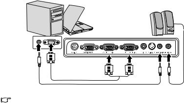
To connect the projector to a notebook or desktop computer:
1.Take the supplied VGA cable and connect one end to the D-Sub output socket of the computer.
2.Connect the other end of the VGA cable to the COMPUTER IN1/COMPUTER IN2 signal input socket on the projector.
3.If you wish to make use of the projector (mixed mono) speaker in your presentations, take a suitable audio cable and connect one end of the cable to the audio output socket of the device, and the other end to the AUDIO IN socket of the projector.
4.If you wish, you can use another suitable audio cable and connect one end of the cable to the AUDIO OUT jack of the projector, and the other end to your external speakers (not supplied).
Once connected, the audio can be controlled by the projector On-Screen Display (OSD) menus. See "Adjusting the sound" on page 35 for details. The built-in speaker will be muted when the AUDIO OUT jack is connected.
The final connection path should be like that shown in the following diagram:
Notebook or desktop computer
Speakers
VGA cable |
|
Audio cable |
Audio cable |
Many notebooks do not turn on their external video ports when connected to a projector. Usually a key combo like FN + F3 or CRT/LCD key turns the external display on/off. Locate a function key labeled CRT/LCD or a function key with a monitor symbol on the notebook. Press FN and the labeled function key simultaneously. Refer to your notebook's documentation to find your notebook's key combination.
14 Connection
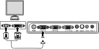
Connecting a monitor
If you want to view your presentation close-up on a monitor as well as on the screen, you can connect the MONITOR OUT signal output socket on the projector to an external monitor with a VGA cable following the instructions below:
To connect the projector to a monitor:
1.Connect the projector to a computer as described in "Connecting a computer" on page 14.
2.Take a suitable VGA cable (only one supplied) and connect one end of the cable to the D-Sub input socket of the video monitor.
Or if your monitor is equipped with a DVI input socket, take a VGA to DVI-A cable and connect the DVI end of the cable to the DVI input socket of the video monitor.
3.Connect the other end of the cable to the MONITOR OUT socket on the projector.
The final connection path should be like that shown in the following diagram:
Monitor
(VGA) |
or |
(DVI-A) |
 (VGA)
(VGA)
 • The D-Sub output only works when an appropriate D-Sub input is made to the COMPUTER IN1 jack.
•If you wish to use this connection method when the projector is in standby mode, make sure the VGA Out function is turned on in the SYSTEM SETUP: Advanced menu. See "VGA Out" on page 43 for details.
Connection 15
Connecting video source devices
You can connect your projector to various video source devices that provide any one of the following output sockets:
•Component video
•S-Video
•Video (composite)
You only need to connect the projector to a single video source device; however each provides a different level of video quality. The method you choose will most likely depend upon the availability of matching terminals on both the projector and the video source device as described below:
Best video quality
The best available video connection method is Component video (not to be confused with composite video). Digital TV tuner and DVD players output Component video natively, so if available on your devices, this should be your connection method of choice in preference to (composite) video.
See "Connecting a Component video source device" on page 17 for how to connect the projector to a component video device.
Better video quality
The S-Video method provides a better quality analog video than standard composite video. If you have both composite video and S-Video output terminals on your video source device, you should elect to use the S-Video option.
See "Connecting an S-Video source device" on page 18 for how to connect the projector to an S-Video device.
Good video quality
Composite video is analog video and will result in a perfectly acceptable, but less than optimal result from your projector. The other methods described above provide better video quality.
See "Connecting a composite video source device" on page 19 for how to connect the projector to a composite video device.
Connecting audio
The projector has one built-in mono speaker which is designed to provide basic audio functionality accompanying data presentations for business purposes only. It is not designed for, nor intended for stereo audio reproduction use as might be expected in home theater or home cinema applications. Any stereo audio input (if provided), is mixed into a common mono audio output through the projector speaker.
If you have a separate sound system, you will most likely want to connect the audio output of your video source device to that sound system, instead of to the mono audio projector. The audio connections are provided for informational purposes only. You need not connect audio to the projector if there is an alternate sound system available, or if audio is not required.
16 Connection
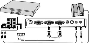
Connecting a Component video source device
Examine your video source device to determine if it has a set of unused Component video output sockets available:
•If so, you can continue with this procedure.
•If not, you will need to reassess which method you can use to connect to the device.
To connect the projector to a Component video source device:
1.Take a Component video to VGA (D-Sub) adaptor cable and connect the end with 3 RCA type connectors to the Component video output sockets of the video source device. Match the color of the plugs to the color of the sockets; green to green, blue to blue, and red to red.
2.Connect the other end of the Component video to VGA (D-Sub) adaptor cable (with a D-Sub type connector) to the COMPUTER IN1/COMPUTER IN2 socket on the projector.
3.If you wish to make use of the projector (mixed mono) speaker in your presentations, take a suitable audio cable and connect one end of the cable to the audio output socket of the device, and the other end to the AUDIO IN socket of the projector.
4.If you wish, you can use another suitable audio cable and connect one end of the cable to the AUDIO OUT jack of the projector, and the other end to your external speakers (not supplied).
Once connected, the audio can be controlled by the projector On-Screen Display (OSD) menus. See "Adjusting the sound" on page 35 for details. The built-in speaker will be muted when the AUDIO OUT jack is connected.
The final connection path should be like that shown in the following diagram:
AV device
Speakers
RS-232 |
MONITOR OUT |
COMPUTER IN1 |
COMPUTER IN2 |
VIDEO S -VIDEO AUDIO IN AUDIO OUT |


 Component video to VGA (D-Sub)

 adaptor cable
Audio cable |
Audio cable |
 • The projector is only capable of playing mixed mono audio, even if a stereo audio input is connected. See "Connecting audio" on page 16 for details.
•If the selected video image is not displayed after the projector is turned on and the correct video source has been selected, check that the video source device is turned on and operating correctly. Also check that the signal cables have been connected correctly.
Connection 17
Loading...