


TSS-1100
6 – Piece Home Theater System
SERVICE MANUAL
Infinity Systems Incorporated |
|
250 Crossways Park Dr. |
|
Woodbury, New York 11797 |
Rev2 1/2006 |

TSS-1100
CONTENTS
BASIC SPECIFICATIONS . . . . . . . . . ………………………………………….1
DETAILED SPECIFICATIONS . . . . . . . . . . . ………………………………….2
CONTROLS. ………………….. .. . …………………………………... . . . . . . .4 CONNECTIONS . . . . . . . . . . . ……….………………………………..…. . . . 5 OPERATION……. . . . . .. . . . . . . . .. .. . . . .. .. . . . . ….……… . . ... . . . . . . .6
EXPLODED VIEW-MECHANICAL PARTS LIST….… . … . .. .. . . .. . … . ….7
TSS-1100 SATELLITES/CENTER & PACKING….… . … . .. .. . . .. . … . …8 TSS-1100 TEST SET-UP & PROCEDURE….… . … . .. .. . . …………….. .9 BLOCK DIAGRAM. . . . ………………... ………………………….... . . .. . … . 10
ELECTRICAL PARTS LIST …………………… ………………..………………11
PCB DRAWINGS. .. . . . . . . . . . . . . . .. . . . . ……………………………….. …14 IC – TRANSISTOR PINOUTS . … . . .. . . . . . ………………………….... . . . 18 SCHEMATIC DIAGRAMS (120v). . ………………………………………..…. . .19 SCHEMATIC DIAGRAMS (230v) . . ……………………………………….…. . .21 PACKAGING. ………………….. .. . ……… ………………………... . . . . . . 23
SPECIFICATIONS |
Satellites & Center Channel |
|
Frequency Range: |
120Hz – 20,000Hz (±3dB) |
|
Recommended Amplifier Power Range: |
10 – 125 watts |
|
Sensitivity: (2.83V @ 1 meter) |
89dB |
|
Nominal Impedance: |
8 ohms |
|
Crossover Frequency: |
3500Hz, 24dB/Octave |
|
Midrange Driver(s): |
Dual 3-1/2" MMD, magnetically shielded |
|
High-Frequency Driver: |
3/4" MMD, magnetically shielded |
|
Dimensions (H x W x D): |
6" x 4-1/8" x 4-3/8" (152mm x 105mm x 111mm) |
|
Weight: |
Satellite |
Center Channel |
|
2.8 lb (1.3kg) |
4.5 lb (2.0kg) |
TSS-1100 Subwoofer |
|
|
Frequency Range: |
29Hz – 150Hz (±3dB) |
|
Amplifier Output: |
250 watts RMS |
|
Low-Frequency Driver: |
12" (305mm) |
|
Crossover Frequency: |
50Hz – 150Hz, 24dB/Octave, continuously variable |
|
Dimensions (H x W x D): |
17-3/4" x 12" x 16-1/8" |
|
|
(451mm x 305mm x 410mm) |
|
Weight: |
44 lb (20kg) |
|
Infinity continually strives to update and improve existing products, as well as create new ones. The specifications and construction details in this and related Infinity publications are therefore subject to change without notice.
1

TSS-1100
TSS-1100 150W Powered Sub/ Plate Amp |
|
|
|
|
|||
|
|
|
|
|
|
|
|
LINE VOLTAGE |
Yes/No |
Hi/Lo Line |
|
Nom. |
Unit |
|
Notes |
US 120vac/60Hz |
Yes |
108-132 |
|
120 |
Vrms |
Normal Operation |
|
EU 230vac/50-60Hz |
Yes |
207-264 |
|
230 |
Vrms |
Normal operation, MOMS required |
|
|
|
|
|
|
|
|
|
|
|
|
|
QA Test |
|
|
|
Parameter |
Specification |
Unit |
|
Limits |
Conditions |
|
Notes |
|
|
|
|
|
|
|
|
Amp Section |
|
|
|
|
|
|
|
Type (Class AB, D, other) |
D |
|
|
|
|
|
|
Load Impedance (speaker) |
5.6 |
Ohms |
|
n/a |
Nominal |
|
|
Rated Output Power (120VAC |
150 |
Watts |
|
110 |
|
Domestic version only 120 VAC-60 Hz |
|
Rated Output Power (230VAC |
150 |
Watts |
|
110 |
|
EU Version only |
230 VAC-50 Hz |
|
|
|
|
|
|
Average RMS power, 3/20 Cycles 50 Hz, Driven |
|
AVG RMS Dynamic Power |
250 |
Watts |
|
225 |
|
6dB above its input sensitivity sensitivity |
|
THD @ Rated Power |
0.5 |
% |
|
1 |
22K filter |
145 Watts |
|
THD @ 1 Watt |
0.1 |
% |
|
0.5 |
22K filter |
|
|
DC Offset |
10 |
mV-DC |
|
30 |
Amplifier output |
|
|
|
|
|
|
|
|
Measured at the amplifier board. 120 Watts @ |
|
Damping factor |
>50 |
DF |
|
20 |
Measured at amplifier board |
50 Hz, THD must be less tan 0.1% |
|
|
|
|
|
|
|
|
|
Input Sensitivity |
|
|
|
|
|
|
|
Input Frequency |
35 |
Hz |
|
35 |
Nominal Freq. |
|
|
L&R |
188 |
mVrms |
|
±2dB |
To 110 Watts, Ap Zo=600 Ohms |
Single input driven |
|
L or R input |
188 |
mVrms |
|
±2dB |
To 110 Watts , Ap Zo=600 Ohms |
Single input driven, LFE switch ON |
|
|
|
|
|
|
|
Single input driven, LP switch to Normal, This |
|
Speaker/Hi Level Input |
1.68 |
Vrms |
|
±2dB |
To 120 Watts |
applies to 230VAC model only |
|
|
|
|
|
|
|
|
|
Signal to Noise |
|
|
|
|
|
|
|
SNR-A-Weighted |
90 |
dBA |
|
85 |
relative to rated power |
A-Weighting filter |
|
SNR-unweighted |
85 |
dBr |
|
80 |
relative to rated power |
22K filter |
|
SNR rel. 1W-unweighted |
65 |
dBr |
|
60 |
relative to 1W Output |
22K filter |
|
|
|
|
|
|
Volume @max, w/ A/P Swept |
|
|
|
|
|
|
1.5 |
Bandpass Measurement (Line |
Line level inputs must be terminated using |
|
Residual Noise Floor |
1 |
mVrms(max) |
|
freq.+ harmonics) (BW=20 Khz) |
1KOHM |
|
|
|
|
|
|
|
|
|
|
Input Impedance |
|
|
|
|
|
|
|
Line Input (L, R,LFE) |
10K |
ohms |
|
n/a |
Nominal |
|
|
Speaker/Hi Level Input |
> 4.7K |
ohms |
|
n/a |
Nominal |
|
|
|
|
|
|
|
|
|
|
Filters |
|
|
|
|
|
|
|
LP filter 4th order fixed |
50-150 |
Hz |
|
± 10 |
2nd Order variable and 2nd order fix |
2nd order variable + 2nd order fix-24 db/Octave |
|
HP Filter 2nd order |
Fixed |
|
|
|
|
|
|
LFE Low pass 2nd order |
200>LP<1K |
Hz |
|
|
LFE input driven only |
|
|
Notch filter (Friend circuit) |
|
|
|
|
F=61 Hz, Q=3.607, Av=-8.62dB |
|
|
HP speaker out connector |
1st order fix |
|
|
|
|
|
|
Left & Right |
200 |
Hz |
|
± 10 |
Speaker input - Spkr out 4 Ohms |
(Applies to 230VAC model only) |
|
Left & Right |
100 |
Hz |
|
± 10 |
Speaker input - Spkr out 8 Ohms |
(Appies to 230VAC model only) |
|
|
|
|
|
|
|
|
|
Limiter |
|
|
|
|
|
|
|
THD at Max. Output Power |
n/a |
n/a |
|
functional |
Maximum Output Power |
Maximum THD as a result of limiting. |
|
|
|
|
|
|
|
|
|
Features |
-- |
|
|
|
|
|
|
Volume pot Taper (lin/log) |
LOG |
-- |
|
functional |
|
A Taper |
|
Speaker input connectors |
YES |
|
|
functional |
|
L&R Speaker input binding post connectors |
|
|
|
|
|
|
|
L&R Speaker out with HP applies only to |
|
HP Speaker out |
YES |
|
|
functional |
|
230VAC models |
|
Phase switch |
0-180 |
deg |
|
functional |
|
|
|
LP Filter defeat switch |
YES |
|
|
functional |
|
Disables LP filter, intended for LFE |
|
|
|
|
|
|
|
|
|
Input Configuration |
|
|
|
|
|
|
|
Line In (L,R) & LFE |
YES |
-- |
|
functional |
|
Dual RCA jack |
|
|
|
|
|
|
|
Binding post connector L&R (Applies to |
|
Spkr/Hi Level In |
YES |
-- |
|
functional |
|
230VAC model only) |
|
|
|
|
|
|
|
|
|
Signal Sensing (ATO) |
|
|
|
|
|
|
|
Auto-Turn-On (yes/no) |
YES |
|
|
functional |
|
|
|
ATO Input test frequency |
50 |
Hz |
|
functional |
|
|
|
ATO Level LFE Input |
2 |
mV |
|
functional |
|
Maximum acceptable level. |
|
|
|
|
|
|
|
Maximum acceptable level. (Applies to 230VAC |
|
ATO Level Speaker in |
40 |
mV |
|
functional |
|
model only) |
|
|
|
|
|
|
Amp connected and AC on, then |
|
|
ATO Turn-on time |
5 |
ms |
|
functional |
input signal applied |
|
|
|
|
|
|
|
T before muting, after line or |
Auto turn of time (T) |
must be 5 > T < 18 |
Auto Mute/ Turn-OFF Time |
15 |
minutes |
|
18 |
speaker level signal is removed |
Minutes |
|
|
|
|
|
|
|
|
|
Power on Delay time |
3 |
sec. |
|
4 |
AC Power Applied |
|
|
2

TSS-1100
|
|
|
QA Test |
|
|
Parameter |
Specification |
Unit |
Limits |
Conditions |
Notes |
|
|
|
|
|
|
|
|
|
|
|
|
Transients/Pops |
|
|
|
|
|
ATO Transient |
5 |
mV-peak |
n/a |
@ Speaker Outputs |
|
Turn-on Transient |
50 |
mV-peak |
2V-pk-pk |
@ Speaker Outputs |
AC Line cycled from OFF to ON |
Turn-off Transient |
50 |
mV-peak |
2V-pk-pk |
@ Speaker Outputs |
AC Line cycled from ON to OFF |
|
|
|
|
|
|
Efficiency |
|
|
|
|
|
Efficiency |
65 |
% |
65 |
|
Nominal Line voltage 120 VAC |
|
|
|
|
|
Maximum allowable input power under nominal |
|
|
|
20 |
|
Input voltage and frequency, HOT or COLD |
Stand-by Input Power |
18 |
Watts |
@ nom. line voltage |
operation. |
|
Power Cons. @ rated power |
170 |
Watts |
180 |
@ nom. line voltage |
120 Watts into 5.6 Ohms @ nominal line voltage |
|
|
|
|
|
|
Protections |
|
|
|
|
|
|
|
|
|
|
Amplifier should resume operation after short |
Short Circuit Protection |
YES |
|
functional |
Direct short at output |
circuit condition removal |
|
|
|
|
|
Temperature rise in accessible metal parts |
|
|
|
|
@1/8 max unclipped Power at 1.06 |
should not exceed 35K rise for domestic version |
|
|
|
|
or 30K rise for European versions (refer to |
|
Thermal Protection |
YES |
|
functional |
times the input voltage |
requirements sheet). |
|
|
|
|
|
Design must insure no Offset at the speaker |
|
|
|
|
|
output under any operating condition including |
DC Offset Protection |
YES |
|
- |
DC present at Speaker Out leads |
abnormal operation |
Line Fuse Rating |
|
|
|
|
|
USA-Domestic |
2 |
Amps |
2 |
Type-T or Slo Blo-250 V |
Internal fuse with UL/SEMKO rated holder |
|
|
|
|
Type-T or Slo Blo-250 V, Low |
|
EU |
1.25 |
Amps |
1.25 |
Breaking capacity |
Internal fuse with UL/SEMKO rated holder |
|
|
|
|
|
|
3
TSS-1100
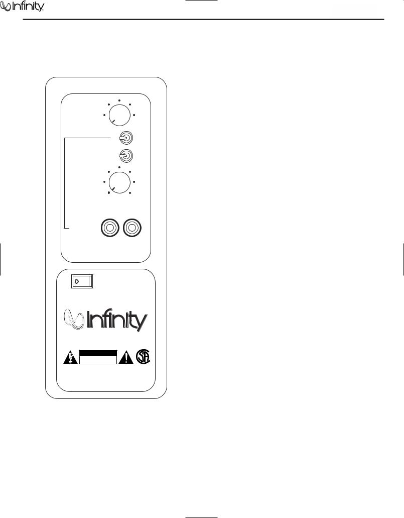
SUBWOOFER CONTROLS
Rear Panel
¡
LEVEL
Min
 Max
Max
LFE NORMAL
™
£PHASE 0˚ |
180˚ |
CROSSOVER
FREQUENCY
¢50Hz |
150Hz |
L ∞ R
LINE LEVEL IN
For LFE use L or R
ON 
 OFF
OFF
§ POWER
|
® |
CAUTION |
|
RISK OF ELECTRIC SHOCK |
® |
DO NOT OPEN |
|
WARNING: TO REDUCE THE RISK OF FIRE OR ELECTRIC SHOCK, |
NRTL/C |
DO NOT EXPOSE THIS APPLIANCE TO RAIN OR MOISTURE. |
CSA22.2 |
UL1492 |
|
AVERTISSEMENT: POUR PRÉVENIR LES RISQUES D’INCENDIE OU |
|
DE CHOC ÉLECTRIQUE, ÉVITER D’EXPOSER CET APPAREIL A LA |
|
PLUIE OU A L’HUMIDITÉ. |
|
Subwoofer-Level Control
LFE/Normal Switch
Phase Switch
Crossover-Frequency Adjustment
Line-Level (LFE) Inputs
Power Switch
A Few Suggestions
We recommend that you do not operate your speakers or subwoofer with the bass, treble and loudness controls set to full boost.This will place undue strain on your electronics and speakers and could damage them.
The volume control setting on your processor/preamp or receiver is not a specific indication of the overall loudness level of the speakers.The only important consideration is the loudness level at which the system can be played, regardless of where the volume control is set.
Always turn down the volume control setting on your processor/ preamp or receiver when changing a cassette or CD, or switching inputs to AM or FM operation. Excessively loud transients (clicks or popping sounds) can damage the satellite speakers and possibly the subwoofer.
Important!
Whenever changing cables, pulling plugs, etc., ALWAYS TURN OFF ALL EQUIPMENT, including the subwoofer.
4
TSS-1100
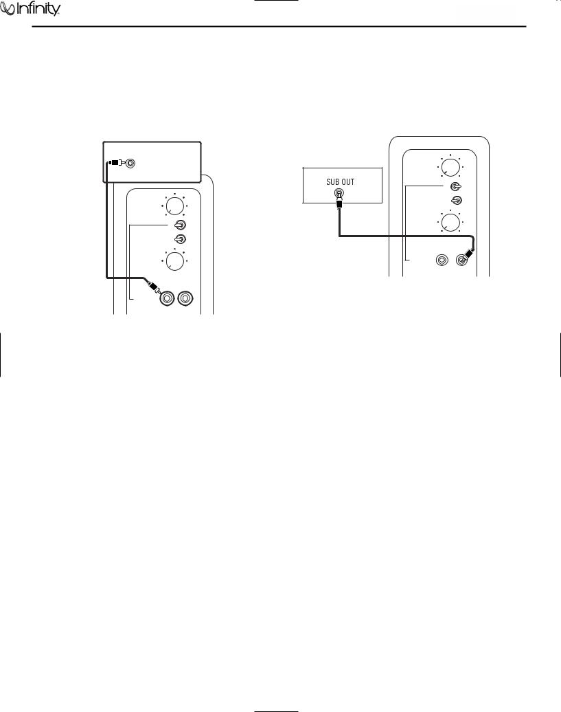
SUBWOOFER CONNECTIONS
If you have a Dolby* Digital or DTS® receiver/ processor with a low-frequency-effects (LFE) or subwoofer output:
|
SUBWOOFER OR |
|
|
LFE OUTPUT |
|
15' |
LEVEL |
|
Min |
Max |
|
subwoofer |
LFE |
NORMAL |
cable |
PHASE 0º |
180º |
included |
80Hz |
|
CROSSOVER
FREQUENCY
50Hz
 150Hz
150Hz
L R
LINE LEVEL IN
For LFE use L or R
Set line-level/LFE switch to “LFE.”
TSS-1100 |
5 |
|
If your receiver/processor does not contain a Dolby Digital or DTS processor but has a subwoofer output:
RECEIVER/PROCESSOR
|
LEVEL |
|
|
Min |
Max |
|
LFE |
NORMAL |
|
PHASE 0º |
180º |
|
80Hz |
|
|
CROSSOVER |
|
|
FREQUENCY |
|
|
50Hz |
150Hz |
15' subwoofer |
L |
R |
cable included |
LINE LEVEL IN |
|
For LFE use L or R
Set line-level/LFE switch to “Normal.”
NOTE: If your receiver/processor has only one sub out, you may use either the L or R input.

TSS-1100
OPERATION
Surround Modes
When using the system in a Dolby Digital or DTS home theater system, make sure all speakers are set to “Small”. When using the TSS-1100 in a Dolby Pro Logic* home theater system, make sure the receiver’s center channel mode is set to “Normal.”
Some Dolby Digital-equipped receivers/processors offer different setup options for each source or surround mode, e.g., CD-stereo, videotape, Dolby, Pro Logic. In each case, follow your equipment’s instructions to ensure that the subwoofer output is turned on and that the speakers are set to “Small” in each mode.
Power On
Plug your subwoofer’s AC cord into a wall outlet. Do not use the outlets on the back of the receiver.
Initially set the Subwoofer Level Control to the“MIN” position.
Turn on the subwoofer by pressing the Power Switch on the rear panel.
Turn on your entire audio system and start a CD or movie soundtrack at a moderate level.
Auto On/Stand-By
With the Power Switch in the ON position, the LED on the front panel will remain lit in red or green to indicate the On/Stand-By mode of the subwoofer.
RED = STAND-BY (No signal detected, Amp Off)
GREEN = ON (Signal detected, Amp On)
The subwoofer will automatically enter the Stand-By mode after approximately 10 minutes when no signal is detected from your system.The subwoofer will then power ON instantly when a signal is detected. During periods of normal use, the Power Switch can be left on. You may turn off the Power Switch for extended periods of nonoperation, e.g., when you are away on vacation.
Adjust Level
Turn the Subwoofer Level Control up about half way. If no sound emanates from the subwoofer, check the AC-line cord and input cables. Are the connectors on the cables making proper contact? Is the AC plug connected to a “live” receptacle? Has the Power Switch been pressed to the “On” position? Once you have confirmed that the subwoofer is active, proceed by playing a CD or DVD. Use a selection that has ample bass information.
Set the overall volume control of the receiver/processor to a comfortable level. Adjust the Subwoofer Level Control until you obtain a pleasing blend of bass. Bass response should not overpower the room but rather be adjusted so there is
a harmonious blend across the entire musical range. Many users have a tendency to set the subwoofer volume too loud,
adhering to the belief that a subwoofer is there to produce lots of bass.This is not entirely true. A subwoofer is there to enhance bass, extending the response of the entire system so the bass can be felt as well as heard. However, overall balance must
be maintained or the music will not sound natural. An experienced listener will set the volume of the subwoofer so its impact on bass response is always there but never obtrusive.
Crossover Adjustment
The Crossover Frequency Control determines the highest frequency at which the subwoofer reproduces sounds. For the TSS-1100, it is recommended that this control be set at 120Hz (approximately the 3 o’clock position).
NOTE: This control will have no effect if the LFE/Normal Switchis set to LFE. If you have a Dolby Digital or DTS receiver/ processor, the Low-Pass Frequency is set by the receiver/ processor. Set the LFE/Normal Switch on the subwoofer to LFE. Consult your owner’s manual to learn how to view or change this setting. A setting of 120Hz – 150Hz is recommended.
Phase Control
The Phase Switch determines whether the subwoofer speaker’s piston-like action moves in and out with the main speakers, 0˚, or opposite the main speakers, 180˚. Proper phase adjustment depends on several variables such as room size, subwoofer placement and listener position. Adjust the phase switch to maximize bass output at the listening position.
Final Positioning
After correctly connecting the TSS-1100 system and verifying that both the subwoofer and all satellite speakers are playing, it is time to optimize the system for your particular listening room. Earlier, you placed the subwoofer in its general location. Finding the exact location for optimum performance sometimes only involves moving the speakers up to a few inches in any direction. We urge you, therefore, to experiment with placement, if possible, until your speakers deliver their full potential.
MAINTENANCE AND SERVICE
The satellite and subwoofer enclosures may be cleaned using a soft cloth to remove fingerprints or to wipe off dust.
All wiring connections should be inspected and cleaned or remade periodically.The frequency of maintenance depends on the metals involved in the connections, atmospheric conditions, and other factors, but once per year is the minimum.
If a problem occurs, make sure that all connections are properly made and clean. If a problem exists in one loudspeaker, reverse the connection wires to the left and right system. If the problem remains in the same speaker, then the fault is with the loudspeaker. If the problem appears in the opposite speaker, the cause is in another component or cable. In the event that your TSS-1100 ever needs service, contact your local Infinity dealer or Infinity directly at 516.674.4INF (USA only) or www.infinitysystems.com for a service center near you.
6

TSS-1100
SERVICE NOTE
Access to woofer:
1)Carefully pry metal grille out of its recess with a sharp pointed instrument such as an awl or dental pick – USE CAUTION and protect the surface of the subwoofer from scratches or dents from the work tool. Work evenly around the perimeter until the grill w/ gasket can be removed.
2)Remove the (6) Phillips screws holding the trim ring to the cabinet.
3)Remove the (6) Phillips screws holding the woofer to the cabinet.
REPLACEMENT: Assure when the woofer is replaced, it is exactly centered in the counterbore.
7
 Loading...