


®
Models OVTR 2, OVTR 3
3-Way Full-Range Floorstanding Speakers
Owner’s Manual
OVTR 2 Part #331250 – USA 120 Vac Only OVTR 3 Part #331251 – USA 120 Vac Only
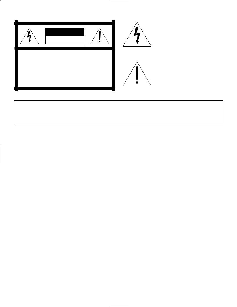
CAUTION
RISK OF ELECTRIC SHOCK
DO NOT OPEN
CAUTION: TO REDUCE THE RISK OF ELECTRIC SHOCK,
DO NOT REMOVE COVER (OR BACK).
NO USER-SERVICEABLE PARTS INSIDE.
REFER SERVICING TO QUALIFIED SERVICE PERSONNEL.
The lightning flash with arrowhead symbol, within an equilateral triangle, is intended to alert the user to the presence of uninsulated “dangerous voltage” within the product’s enclosure that may be of sufficient magnitude to constitute a risk of electric shock to persons.
The exclamation point within an equilateral triangle is intended to alert the user to the presence of important operating and maintenance (servicing) instructions in the literature accompanying the product.
THIS INFINITY PRODUCT IS DESIGNED FOR (USA) 120 VOLT USE ONLY! FOR DETAILED SAFETY PRECAUTIONS, PLEASE SEE THE ENCLOSED LEAFLET “IMPORTANT SAFETY INSTRUCTIONS” (P/N 330100-001).

3-WAY FLOOR-STANDING
SPEAKERS WITH
INTEGRATED POWERED
SUBWOOFERS...
ABOUT THIS MANUAL...
PARTS LIST...
TOOLS AND SUPPLIES
(NOT ENCLOSED)...
INTRODUCTION
Infinity Compositions Overture OVTR 2 and OVTR 3 speaker systems are a pair of advanced, 3-way full-range, floor-standing speakers with integrated powered subwoofers. Housed in slender columns, these highly-efficient speakers require only minimal power to produce sound levels greater than those heard in a movie theater. Moreover, even though they excel at reproduction of front left and right home-theater channels, you’ll find these speakers also provide the highest musical fulfillment when listening to CDs, LPs, or tapes.
To start enjoying your new Compositions Overture speakers, first read and then perform all instructions listed in this manual, as well as those found in the owner’s manuals of associated components in your audio system. Also, please read the enclosed Important Safety Instructions for detailed safety precautions. Save all instructions for future reference. These speakers are covered by a limited five-year warranty (see page 12), so save the bill of sale to protect your purchase and aid in any service-related questions.
UNPACKING THE SPEAKERS
Finish unpacking each speaker box. If you suspect damage from transit, report it immediately to your dealer and/or delivery service. Keep the shipping cartons and packing materials for future use. Open each accessory pack and verify the following contents:
(4) Feet
(4) Locking Nuts
(4) Nylon Domes
(1) Wrench
(2) Spare 5A (250V) Fuses for OVTR 2 or
(2) Spare 5 A (250V) Fuses for OVTR 3
Owner’s Manual (P/N 331350-001) and Warranty Registration Card You may also need the following tools and supplies:
High-quality speaker wire (also see Wiring The System on page 5)
Wire strippers
Small flat-blade screwdriver (for fuse replacement, if needed)
(4) Banana plugs or spade terminals (optional)
Level (optional for adjusting feet)
Compositions Overture OVTR 2/OVTR 3 – Owner’s Manual 1

IMPORTANT!
Figure 1. This bottom view shows the four locations of the foot holes and the ac cord channel on a Compositions Overture OVTR 2 or OVTR 3 speaker.
NOTE: Do not unfasten any screws. There are no user-serviceable parts inside the speaker. For service, please contact an authorized Infinity technician for help (also see “Troubleshooting” on page 8 and “Limited Five-Year Warranty” on page 12).
INSTALLING THE FEET
Compositions Overture OVTR 2 and OVTR 3 speakers use dual-purpose feet with spike and round ends for carpeted or hard-surface floors. Refer to Figures 1 and 2 as you perform the following steps:
1.Lay each speaker on its side and locate the four threaded holes on the bottom (see Figure 1).
For safety reasons, each speaker base contains a cord channel designed to keep the ac power cord away from the feet. During shipping, the cord may become dislodged from its intended position and upon subsequent speaker placement may be accidentally pierced by spiked feet. Please make sure that the 120 Vac power cord is inside the cord channel (see Figure 1).
Foot Hole |
F U S E |
Foot Hole |
|
S U F |
|
|
E |
|
|
Fuse Holder |
|
CAUTION
RISK OF ELECTRIC SHOCK
DO NOT OPEN
|
AVIS: RISQUE DE CHOC ELECTRIQUE - NE PAS OUVRIR |
|
|
CAUTION: |
ATTENTION: |
~120V 60Hz |
FOR CONTINUED PROTECTION AGAINST |
UTILSER UN FUSIBLE DE |
RISK OF FIRE, REPLACE ONLY WITH SAME |
RECHANGE DE MEME |
|
300W MAX |
TYPE OF FUSE: 2AG SB 250V |
TYPE ET CALIBRE |
OVTR 2 or |
|
OVTR 3 |
|
(bottom view) |
|
Foot Hole |
Foot Hole |
120 Vac Power Cord
2 Compositions Overture OVTR 2/OVTR 3 – Owner’s Manual
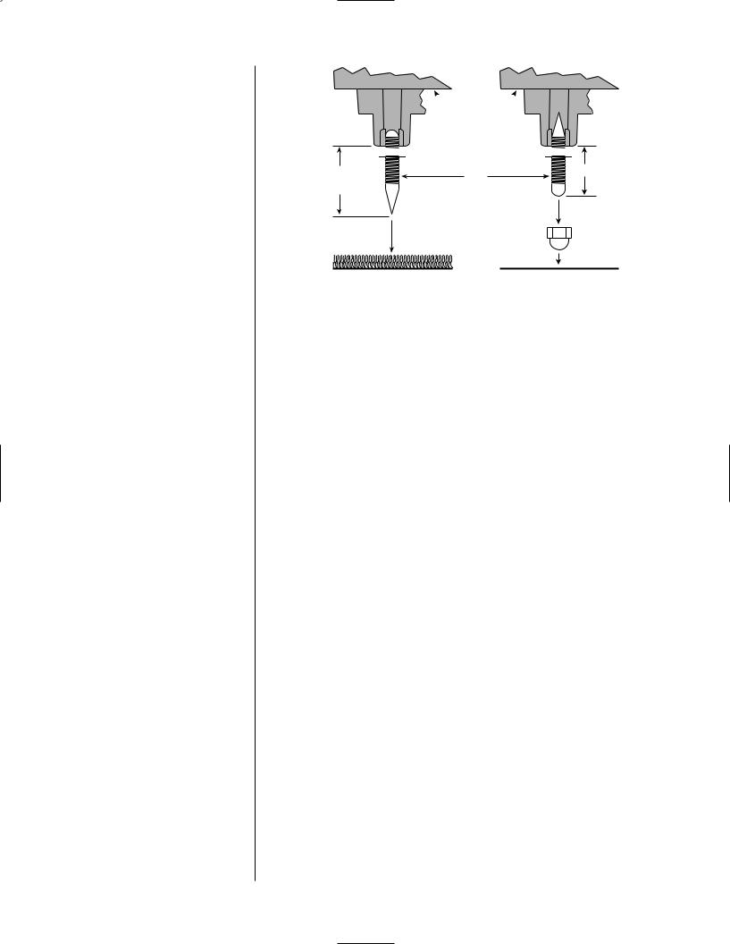
Figure 2. This cross-section shows how to install a foot onto the bottom of a Compositions Overture OVTR 2 or OVTR 3 speaker.
 Bottom
Of Speaker


 Locking Nut


5 ⁄8" min. |
5 |
⁄8" |
|
Foot |
|
11⁄8" max. 
 round end
spike end
Nylon Dome
(optional for wood floors)
CARPETED |
HARD-SURFACE |
FLOORS |
FLOORS |
2.For carpets, screw the round end of a foot into each hole and handtighten a nut onto each one (see Figure 2). Leave a minimum of 5⁄8" exposed spike to keep the carpet from blocking the port. (On thicker carpets, you can increase the length of exposed spike up to 1 1 ⁄8 ").
For hard-surface floors, screw the spike end into each hole instead and leave 5⁄8" of round end exposed.
3.Carefully flip each speaker upright to sit on its feet.
4.If needed, adjust the feet so each speaker is level and then tighten each nut with the enclosed wrench. To protect hard surfaces (e.g., wood floors), thread a nylon dome onto each round end (see Figure 2).
Compositions Overture OVTR 2/OVTR 3 – Owner’s Manual 3
 Loading...