


 Loading...
Operating Manual
Incl. EC Declaration of Conformity
VGC402
Two-Channel Measurement and Control Unit
VGC403
Three-Channel Measurement and Control Unit
ch |
para |
ch |
para |
tinb07e1-e 2011-07 |
1 |

Contents
1 |
Introduction |
|
1.1 |
Validity . . . . . . . . . . . . . . . . . . . . . . . . . . . . |
. 4 |
1.1.1 |
Part number . . . . . . . . . . . . . . . . . . . . . . . . . |
. 4 |
1.1.2 |
Firmware version . . . . . . . . . . . . . . . . . . . . . |
. 4 |
1.1.3 |
Type label . . . . . . . . . . . . . . . . . . . . . . . . . . |
. 4 |
1.2 |
Intended use. . . . . . . . . . . . . . . . . . . . . . . . |
. 4 |
1.2.1 |
Liability and warranty . . . . . . . . . . . . . . . . . . |
. 4 |
1.3 |
Product versions . . . . . . . . . . . . . . . . . . . . |
. 4 |
1.4 |
Safety . . . . . . . . . . . . . . . . . . . . . . . . . . . . . |
. 5 |
1.4.1 |
Personnel qualifications . . . . . . . . . . . . . . . . |
. 5 |
1.4.2 |
Illustration of residual dangers . . . . . . . . . . . |
. 5 |
1.4.3 |
General safety instructions . . . . . . . . . . . . . |
. 5 |
1.4.4 |
Disconnecting device . . . . . . . . . . . . . . . . . . |
. 6 |
2 |
Technical data |
|
2.1 |
General data . . . . . . . . . . . . . . . . . . . . . . . . |
. 7 |
2.1.1 |
Mechanical data. . . . . . . . . . . . . . . . . . . . . . |
. 7 |
2.1.2 |
Ambience . . . . . . . . . . . . . . . . . . . . . . . . . . . |
. 7 |
2.1.3 |
Operation . . . . . . . . . . . . . . . . . . . . . . . . . . . |
. 7 |
2.2 |
Mains connection. . . . . . . . . . . . . . . . . . . . |
. 7 |
2.3 |
Channels. . . . . . . . . . . . . . . . . . . . . . . . . . . |
. 8 |
2.3.1 |
Sensor connections . . . . . . . . . . . . . . . . . . . |
. 8 |
2.3.2 |
Sensor supply . . . . . . . . . . . . . . . . . . . . . . . |
. 8 |
2.3.3 |
Measuring technique . . . . . . . . . . . . . . . . . . |
. 8 |
2.4 |
Switching functions. . . . . . . . . . . . . . . . . . |
. 8 |
2.4.1 |
Switching function relay . . . . . . . . . . . . . . . . |
. 9 |
2.4.2 |
Error signal relay . . . . . . . . . . . . . . . . . . . . . |
. 9 |
2.5 |
Outputs . . . . . . . . . . . . . . . . . . . . . . . . . . . . |
. 9 |
2.5.1 |
Analog output. . . . . . . . . . . . . . . . . . . . . . . . |
. 9 |
2.5.2 |
Recorder output . . . . . . . . . . . . . . . . . . . . . . |
. 9 |
2.5.3 |
Computer interface . . . . . . . . . . . . . . . . . . . |
. 9 |
2.6 |
Scope of delivery . . . . . . . . . . . . . . . . . . . . |
. 9 |
3 |
Installation |
|
3.1 |
Unpacking. . . . . . . . . . . . . . . . . . . . . . . . . . |
10 |
3.2 |
Mechanical installation . . . . . . . . . . . . . . . |
10 |
3.2.1 |
Desktop unit . . . . . . . . . . . . . . . . . . . . . . . . . |
10 |
3.2.2 |
Control panel mounted. . . . . . . . . . . . . . . . . |
10 |
3.2.3 |
Mounting the unit in a rack. . . . . . . . . . . . . . |
11 |
3.3 |
Connecting . . . . . . . . . . . . . . . . . . . . . . . . . |
11 |
3.3.1 |
Back side of the device . . . . . . . . . . . . . . . . |
11 |
3.3.2 |
Mains connection . . . . . . . . . . . . . . . . . . . . . |
12 |
3.3.3 |
Ground . . . . . . . . . . . . . . . . . . . . . . . . . . . . . |
12 |
3.3.4 |
SENSOR . . . . . . . . . . . . . . . . . . . . . . . . . . . |
12 |
3.3.5 |
RELAY . . . . . . . . . . . . . . . . . . . . . . . . . . . . . |
13 |
3.3.6 CONTROL . . . . . . . . . . . . . . . . . . . . . . . . . . 14 3.3.7 RS232C . . . . . . . . . . . . . . . . . . . . . . . . . . . . 14
4 Operation
4.1 Front panel . . . . . . . . . . . . . . . . . . . . . . . . . 15
4.1.1 Display . . . . . . . . . . . . . . . . . . . . . . . . . . . . . 15 4.1.2 Control buttons. . . . . . . . . . . . . . . . . . . . . . . 15
4.2 Switching on and off . . . . . . . . . . . . . . . . . 16
4.2.1 Switching on. . . . . . . . . . . . . . . . . . . . . . . . . 16 4.2.2 Switching off. . . . . . . . . . . . . . . . . . . . . . . . . 16 4.2.3 Waiting time . . . . . . . . . . . . . . . . . . . . . . . . . 16
4.3 Operating modes . . . . . . . . . . . . . . . . . . . . 16
4.4 Measurement mode . . . . . . . . . . . . . . . . . . 17
4.4.1 Selection . . . . . . . . . . . . . . . . . . . . . . . . . . . 17 4.4.2 Description . . . . . . . . . . . . . . . . . . . . . . . . . . 17 4.4.3 Control button functions . . . . . . . . . . . . . . . . 17
4.5 Parameter mode. . . . . . . . . . . . . . . . . . . . . 19
4.5.1 Selection . . . . . . . . . . . . . . . . . . . . . . . . . . . 19 4.5.2 Parameter groups . . . . . . . . . . . . . . . . . . . . 19 4.5.3 Basic operation . . . . . . . . . . . . . . . . . . . . . . 20
5 Parameter
5.1Switching function parameters (PArA SP)21
5.1.1 Fundamental terms . . . . . . . . . . . . . . . . . . . 21 5.1.2 Configuring switching functions . . . . . . . . . . 22 5.1.3 Adjustment range. . . . . . . . . . . . . . . . . . . . . 22
5.2 Sensor parameters (PArA SEn). . . . . . . . . 23
5.2.1 Measurement filter (FiLt) . . . . . . . . . . . . . . . 23 5.2.2 Gas type (GAS) . . . . . . . . . . . . . . . . . . . . . . 24 5.2.3 Measuring range (FS) . . . . . . . . . . . . . . . . . 24 5.2.4 Offset (oFS) . . . . . . . . . . . . . . . . . . . . . . . . . 24 5.2.5 Degas function (dEGAS) . . . . . . . . . . . . . . . 25 5.2.6 Sensor activation (S-on) . . . . . . . . . . . . . . . 25 5.2.7 Switch-on threshold (t-on) . . . . . . . . . . . . . . 25 5.2.8 Sensor deactivation (S-oFF) . . . . . . . . . . . . 25 5.2.9 Switch-off threshold (t-off) . . . . . . . . . . . . . . 26 5.2.10 Emission (EMi) . . . . . . . . . . . . . . . . . . . . . . . 26 5.2.11 Filament selection (FiL) . . . . . . . . . . . . . . . . 26 5.2.12 Pirani range extension (PrE) . . . . . . . . . . . . 26
5.3 General parameters (PArA GEn) . . . . . . . . 27
5.3.1 Unit of measurement (unit) . . . . . . . . . . . . . 27 5.3.2 Baud rate (bAud) . . . . . . . . . . . . . . . . . . . . . 27 5.3.3 Display format (diGit) . . . . . . . . . . . . . . . . . . 27 5.3.4 Default parameters (dEF). . . . . . . . . . . . . . . 27 5.3.5 Recorder output (Ao) . . . . . . . . . . . . . . . . . . 27 5.3.6 Error signal relay (Err-r) . . . . . . . . . . . . . . . . 29
5.4 Test parameters (PArA tESt) . . . . . . . . . . . 29
2 |
tinb07e1-e 2011-07 Vacuum Gauge Controller |

5.4.1 |
Selection . . . . . . . . . . . . . . . . . . . . . . . . . . . |
29 |
5.4.2 |
Firmware version (Pnr) . . . . . . . . . . . . . . . . |
29 |
5.4.3 |
Watchdog control (dt-C). . . . . . . . . . . . . . . . |
29 |
5.4.4 |
Torr lock (tr-L) . . . . . . . . . . . . . . . . . . . . . . . |
30 |
5.4.5 |
Parameter setup lock (LoC) . . . . . . . . . . . . . |
30 |
5.4.6 |
RAM test (rA-t). . . . . . . . . . . . . . . . . . . . . . . |
30 |
5.4.7 |
EPROM test (EP-t). . . . . . . . . . . . . . . . . . . . |
30 |
5.4.8 |
EEPROM test (EE-t) . . . . . . . . . . . . . . . . . . |
30 |
5.4.9 |
Display test (di-t) . . . . . . . . . . . . . . . . . . . . . |
30 |
5.4.10 |
A/D converter signal (Ad-S). . . . . . . . . . . . . |
30 |
5.4.11 |
A/D converter ID (Ad-i) . . . . . . . . . . . . . . . . |
31 |
5.4.12 |
I/O test (io-t). . . . . . . . . . . . . . . . . . . . . . . . . |
31 |
5.4.13 |
RS232C test (rS-t) . . . . . . . . . . . . . . . . . . . . |
31 |
6 |
Computer interface |
|
6.1 |
Basics . . . . . . . . . . . . . . . . . . . . . . . . . . . . . |
32 |
6.1.1 |
Connection. . . . . . . . . . . . . . . . . . . . . . . . . . |
32 |
6.1.2 |
Nomenclature . . . . . . . . . . . . . . . . . . . . . . . |
32 |
6.2 |
Communication . . . . . . . . . . . . . . . . . . . . . |
32 |
6.2.1 |
Protocol . . . . . . . . . . . . . . . . . . . . . . . . . . . . |
32 |
6.2.2 |
Sending (Host --> Unit) . . . . . . . . . . . . . . . . |
32 |
6.2.3 |
Receiving (Unit --> Host) . . . . . . . . . . . . . . . |
33 |
6.2.4 |
Examples . . . . . . . . . . . . . . . . . . . . . . . . . . . |
33 |
6.2.5 |
Number formats . . . . . . . . . . . . . . . . . . . . . . |
33 |
6.2.6Continuous transmission of measurements. 33
6.3 |
Mnemonics . . . . . . . . . . . . . . . . . . . . . . . . . |
34 |
6.3.1 |
Overview . . . . . . . . . . . . . . . . . . . . . . . . . . . |
34 |
6.3.2 |
AOM. . . . . . . . . . . . . . . . . . . . . . . . . . . . . . . |
35 |
6.3.3 |
BAU . . . . . . . . . . . . . . . . . . . . . . . . . . . . . . . |
35 |
6.3.4 |
COM . . . . . . . . . . . . . . . . . . . . . . . . . . . . . . |
35 |
6.3.5 |
COR. . . . . . . . . . . . . . . . . . . . . . . . . . . . . . . |
36 |
6.3.6 |
DCD . . . . . . . . . . . . . . . . . . . . . . . . . . . . . . . |
36 |
6.3.7 |
DGS . . . . . . . . . . . . . . . . . . . . . . . . . . . . . . . |
36 |
6.3.8 |
ERA . . . . . . . . . . . . . . . . . . . . . . . . . . . . . . . |
36 |
6.3.9 |
ERR . . . . . . . . . . . . . . . . . . . . . . . . . . . . . . . |
36 |
6.3.10 |
EUM. . . . . . . . . . . . . . . . . . . . . . . . . . . . . . . |
37 |
6.3.11 |
FIL . . . . . . . . . . . . . . . . . . . . . . . . . . . . . . . . |
37 |
6.3.12 |
FSR . . . . . . . . . . . . . . . . . . . . . . . . . . . . . . . |
37 |
6.3.13 |
FUM . . . . . . . . . . . . . . . . . . . . . . . . . . . . . . . |
38 |
6.3.14 |
GAS . . . . . . . . . . . . . . . . . . . . . . . . . . . . . . . |
38 |
6.3.15 |
HVC . . . . . . . . . . . . . . . . . . . . . . . . . . . . . . . |
38 |
6.3.16 |
ITR . . . . . . . . . . . . . . . . . . . . . . . . . . . . . . . . |
38 |
6.3.17 |
LOC . . . . . . . . . . . . . . . . . . . . . . . . . . . . . . . |
38 |
6.3.18 |
OFC . . . . . . . . . . . . . . . . . . . . . . . . . . . . . . . |
39 |
6.3.19 |
OFD . . . . . . . . . . . . . . . . . . . . . . . . . . . . . . . |
39 |
6.3.20 |
PNR . . . . . . . . . . . . . . . . . . . . . . . . . . . . . . . |
39 |
6.3.21 |
PR1 . . . . . . . . . . . . . . . . . . . . . . . . . . . . . . . |
39 |
6.3.22 |
PRE . . . . . . . . . . . . . . . . . . . . . . . . . . . . . . . |
40 |
6.3.23 |
PRX . . . . . . . . . . . . . . . . . . . . . . . . . . . . . . . |
40 |
6.3.24 |
RES . . . . . . . . . . . . . . . . . . . . . . . . . . . . . . . |
40 |
6.3.25 |
SAV . . . . . . . . . . . . . . . . . . . . . . . . . . . . . . . |
40 |
6.3.26 |
SC1 . . . . . . . . . . . . . . . . . . . . . . . . . . . . . . . |
41 |
6.3.27 |
SP1 . . . . . . . . . . . . . . . . . . . . . . . . . . . . . . . |
41 |
6.3.28 |
SPS . . . . . . . . . . . . . . . . . . . . . . . . . . . . . . . |
41 |
6.3.29 |
TAD . . . . . . . . . . . . . . . . . . . . . . . . . . . . . . . |
42 |
6.3.30 |
TDI . . . . . . . . . . . . . . . . . . . . . . . . . . . . . . . . |
42 |
6.3.31 |
TEE . . . . . . . . . . . . . . . . . . . . . . . . . . . . . . . |
42 |
6.3.32 |
TEP . . . . . . . . . . . . . . . . . . . . . . . . . . . . . . . |
42 |
6.3.33 |
TID . . . . . . . . . . . . . . . . . . . . . . . . . . . . . . . . |
43 |
6.3.34 |
TIO. . . . . . . . . . . . . . . . . . . . . . . . . . . . . . . . |
43 |
6.3.35 |
TKB . . . . . . . . . . . . . . . . . . . . . . . . . . . . . . . |
43 |
6.3.36 |
TLC . . . . . . . . . . . . . . . . . . . . . . . . . . . . . . . |
44 |
6.3.37 |
TRA . . . . . . . . . . . . . . . . . . . . . . . . . . . . . . . |
44 |
6.3.38 |
TRS . . . . . . . . . . . . . . . . . . . . . . . . . . . . . . . |
44 |
6.3.39 |
UNI. . . . . . . . . . . . . . . . . . . . . . . . . . . . . . . . |
44 |
6.3.40 |
WDT. . . . . . . . . . . . . . . . . . . . . . . . . . . . . . . |
44 |
7 |
Maintenance and service |
|
7.1 |
Maintenance . . . . . . . . . . . . . . . . . . . . . . . . |
45 |
7.1.1 |
Cleaning. . . . . . . . . . . . . . . . . . . . . . . . . . . . |
45 |
7.2 |
Program transfer mode . . . . . . . . . . . . . . . |
45 |
7.2.1 |
Preparations and selection . . . . . . . . . . . . . |
45 |
7.2.2 |
Program transfer . . . . . . . . . . . . . . . . . . . . . |
45 |
7.2.3 |
Restarting . . . . . . . . . . . . . . . . . . . . . . . . . . |
45 |
7.3 |
Calibration . . . . . . . . . . . . . . . . . . . . . . . . . |
46 |
7.3.1 |
Basics . . . . . . . . . . . . . . . . . . . . . . . . . . . . . |
46 |
7.3.2 |
CAO . . . . . . . . . . . . . . . . . . . . . . . . . . . . . . . |
46 |
7.3.3 |
CAF . . . . . . . . . . . . . . . . . . . . . . . . . . . . . . . |
46 |
7.3.4 |
Calibrating the unit. . . . . . . . . . . . . . . . . . . . |
46 |
8 |
Troubleshooting |
|
8.1 |
Fault indication . . . . . . . . . . . . . . . . . . . . . |
48 |
8.2 |
Error messages . . . . . . . . . . . . . . . . . . . . . |
48 |
8.3 |
Technical support . . . . . . . . . . . . . . . . . . . |
48 |
9 |
Storage and disposal |
|
9.1 |
Packaging. . . . . . . . . . . . . . . . . . . . . . . . . . |
49 |
9.2 |
Storage . . . . . . . . . . . . . . . . . . . . . . . . . . . . |
49 |
9.3 |
Disposal . . . . . . . . . . . . . . . . . . . . . . . . . . . |
49 |
Appendix
Conversion tables . . . . . . . . . . . . . . . . . . . 50
Weights . . . . . . . . . . . . . . . . . . . . . . . . . . . . 50 Pressure . . . . . . . . . . . . . . . . . . . . . . . . . . . 50 Linear measures . . . . . . . . . . . . . . . . . . . . . 50 Temperature . . . . . . . . . . . . . . . . . . . . . . . . 50
Default parameters . . . . . . . . . . . . . . . . . . 51 Literature . . . . . . . . . . . . . . . . . . . . . . . . . . 51 Index . . . . . . . . . . . . . . . . . . . . . . . . . . . . . . 52 ETL Certification . . . . . . . . . . . . . . . . . . . . 55 EC Declaration of Conformity. . . . . . . . . . 55
tinb07e1-e 2011-07 Vacuum Gauge Controller |
3 |

1 Introduction
1.1 Validity
1.1.1Part number
This document applies to the following products:
Part number |
Product |
|
|
398-020 |
VGC402 |
398-021 |
VGC403 |
|
|
The part number can be found on the type label which is attached to one side of the unit.
1.1.2Firmware version
This Operating Manual is based on the firmware version 302-534-D.
If the unit does not work as described, please check if it is equipped with this firmware version. See Chapter 5.4.2 Firmware version (Pnr), 29.
1.1.3Type label
There is a type label attached to one side of the unit. In all communication with INFICON, please state the information on the type label. For this purpose you may want to copy the information into the space provided below:
1.2 Intended use
The VGC402 and VGC403 Vacuum Gauge Controller is a display and control unit for vacuum gauges made by INFICON.
It is used together with vacuum gauges of the PSG, PCG, PEG, MPG, CDG, BPG, BCG and HPG series and is used for total pressure measurements. The vacuum gauges must be operated in accordance with their respective operating manuals.
In the following, the VGC402 or VGC403 Vacuum Gauge Controller will be referred to as «Vacuum Gauge Controller».
1.2.1Liability and warranty
INFICON assumes no liability and the warranty becomes null and void if the end user or third parties
•Disregard the information in this document
•Use the product in a non-conforming manner
•Make any kind of alterations (modifications, repair work, etc.) to the product
•Use the product with accessories not listed in the corresponding product documentation
We reserve the right to make technical changes without prior notice. The figures are non-committal.
Model:
PN:
SN:
V Hz W 
Fig. 1-1 Type label (example)
1.3 Product versions
The Vacuum Gauge Controller is available in two different versions: VGC402 and VGC403. The two products differ from each other with regard to:
•Number of channels
•Number of switching functions
•Power consumption
•Weight
See Chapter 2 Technical data, 7.
This Operating Manual describes both the VGC402 and the VGC403.
4 |
tinb07e1-e 2011-07 Vacuum Gauge Controller |
1.4 Safety
1.4.1Personnel qualifications
All work described in this document may only be carried out by persons who have suitable technical training and the necessary experience or who have been instructed by the end user of the product.
1.4.2Illustration of residual dangers
This Operating Manual illustrates safety notes concerning residual dangers as follows:
 DANGER
DANGER indicates an imminently hazardous situation which, if not avoided, will result in death or severe injury.
1.4.3General safety instructions
For all work you are going to do, adhere to the applicable safety regulations.
Also observe all safety notes given in this document and forward the information to all other users of the product.
In particular, pay attention to the following safety notes:
 DANGER
Mains power.
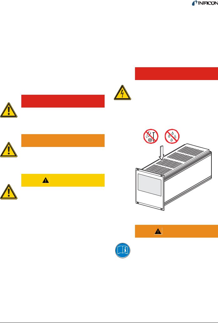
The Vacuum Gauge Controller contains parts which are connected to the mains supply.
Make sure that no objects enter through the louvers of the unit. Keep the unit dry. Do not open the unit.
 WARNING
WARNING indicates a potentially hazardous situation which, if not avoided, could result in death or severe injury.
CAUTION |
|
CAUTION indicates a potentially hazardous |
|
situation which, if not avoided, may result in |
|
moderate or minor injury or in property dam- |
|
age. |
|
NOTE: |
Fig. 1-2 Do not insert objects through louvers and keep unit dry |
A note such as this one indicates particularly impor- |
|
tant, but not safety-relevant information. |
WARNING |
|
|
|
Improper use. |
|
Improper use can damage the Vacuum |
|
Gauge Controller. |
|
Use the Vacuum Gauge Controller only as in- |
|
tended by the manufacturer. See Chapter 1.2 |
|
Intended use, 4. |
tinb07e1-e 2011-07 Vacuum Gauge Controller |
5 |
 WARNING
Improper installation and operation data.
Improper installation and operation data may damage the Vacuum Gauge Controller.
Strictly adhere to the stipulated installation and operation data.
1.4.4Disconnecting device
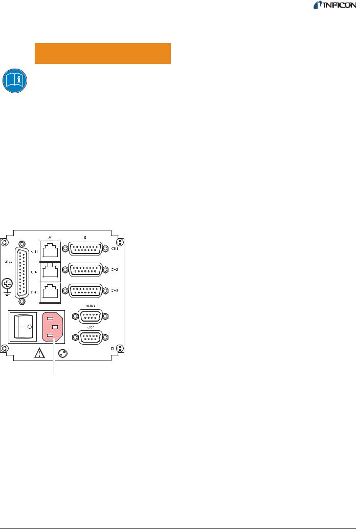
The Vacuum Gauge Controller is equipped with a disconnecting device according to EN 61010-1.
The disconnecting device is located at the back of the Vacuum Gauge Controller. See Fig. 1-3, 6.
The disconnecting device must be readily identifiable and easily reached by the user.
In order to disconnect the Vacuum Gauge Controller from mains, you must unplug the mains cable.
A |
Fig. 1-3 Back side of the VGC403
A Disconnecting device
6 |
tinb07e1-e 2011-07 Vacuum Gauge Controller |
2 Technical data
2.1 General data
2.1.1Mechanical data
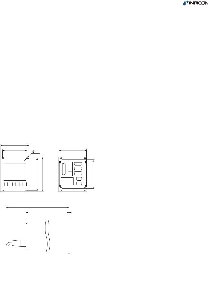
Dimensions |
Width: 106.3 mm |
|
Height: 128.5 mm (3 HE) |
|
Depth: 207 mm |
|
See Fig. 2-1, 7 |
Weight |
VGC402: |
|
1.04 kg |
|
VGC403: |
|
1.16 kg |
Use |
Desktop unit |
|
Control panel mounted |
|
Mounting the unit in a rack |
106.3 |
|
|
91.4 |
|
103 |
3.5 |
|
|
122.5 |
128.5 |
110 |
285 |
|
|
|
204.5 |
2.5 |
|
|
|
|
|
|
|
|
|
|
|
|
|
|
|
|
|
|
Fig. 2-1 Dimensions (in mm)
2.1.2Ambience
Temperature |
Storage: -20…+60 °C |
|
Operation: +5…+50 °C |
Relative humidity |
Max. 80 % (bis 31 °C), |
|
decreasing to |
|
max. 50 % (above 40 °C) |
Use |
Indoors only |
|
Altitude max. 2000 m NN |
Pollution degree |
II |
Protection type |
IP20 |
2.1.3Operation
Manually |
Via 4 control buttons on the |
|
front panel |
Remote control |
Via RS232C interface |
2.2 Mains connection
Voltage |
90…250 VAC |
Frequency |
50…60 Hz |
Power consumption |
VGC402: |
|
Max. 45 W |
|
VGC403: |
|
Max. 65 W |
Overvoltage category |
II |
Protection class |
1 |
Connection |
European appliance con- |
|
nector IEC 320 C14 |
tinb07e1-e 2011-07 Vacuum Gauge Controller |
7 |

2.3 Channels
2.3.1Sensor connections
Number of channels |
VGC402: 2 |
|
VGC403: 3 |
Sensor connections per |
RJ45 (FCC 68) |
channel |
D-Sub, 15 pins, female |
|
(connected in parallel) |
Compatible sensors |
Pirani: |
|
PSG400, PSG400-S, |
|
PSG100-S, PSG101-S, |
|
PSG500, PSG500-S, |
|
PSG502-S, PSG510-S, |
|
PSG512-S, PSG550, |
|
PSG552, PSG554 |
|
Pirani / Capacitance: |
|
PCG400, PCG400-S, |
|
PCG550, PCG552, PCG554 |
|
Cold cathode: |
|
PEG100 |
|
Cold cathode / Pirani: |
|
MPG400, MPG401 |
|
Capacitance: |
|
CDG025, CDG025D, |
|
CDG045, CDG045D, |
|
CDG100, CDG100D, |
|
CDG160D |
|
Hot ionization / Pirani: |
|
BPG400, BPG402 |
|
HPG400 |
|
Hot ionization / Pirani / |
|
Capacitance: BCG450 |
2.3.3Measuring technique
Measuring ranges |
Sensor dependent |
Error of measurement |
Gain error: |
|
≤ 0.005 % FS |
|
Offset error: |
|
≤ 0.01 % FS |
Measuring rate |
50 s-1 |
Display rate |
10 s-1 |
Filter time constant |
Slow: |
|
Approx. 1.0 s (fg = 0.16 Hz) |
|
Normal (nor): |
|
Approx. 0.3 s (fg = 0.53 Hz) |
|
Fast: |
|
Approx. 0.06 s (fg = 2.65 Hz) |
Unit of measurement |
mbar, Pa, Torr, Micron |
Possible adjustments |
Linear sensors (CDG): |
|
Zero-adjust |
|
Logarithmic sensors (PSG, |
|
PCG, PEG, MPG, BPG, |
|
BCG, HPG): |
|
Fixed correction factors for |
|
N2, Ar, H2, or a variable cor- |
|
rection factor in the range |
|
0.10…9.99 |
A/D converter |
Resolution > 16 bit |
NOTE:
The measurements of the BPG/BCG/HPG/CDGxxxD are transferred digitally.
2.3.2Sensor supply
Voltage |
+24 VDC ±5 % |
Current |
500 mA |
|
(750 mA short-time) |
Fuse |
900 mA via PTC element |
|
Self-resetting after switching |
|
the unit off or unplugging the |
|
sensor. |
|
The supply meets the |
|
requirements of a ground |
|
protective extra low voltage |
|
(SELV). |
2.4 Switching functions
Number of switching |
VGC402: 4 |
functions |
VGC403: 6 |
Assignment |
Can be configured any way |
Delay time |
Filter time constant depen- |
|
dent |
Adjustment range |
Sensor dependent |
Hysteresis |
Linear sensors (CDG): ≥ 1 |
|
% FS |
|
Logarithmic sensors (PSG, |
|
PCG, PEG, MPG, BPG, |
|
BCG, HPG): |
|
≥ 10 % of measurement |
8 |
tinb07e1-e 2011-07 Vacuum Gauge Controller |

2.4.1Switching function relay
Contact type |
Change-over contact, float- |
|
ing |
Load (ohmic) |
Max. 60 VDC, 0.5 A |
|
Max. 30 VAC, 1 A |
Lifetime |
Mechanical: |
|
107 cycles |
|
Electrical: |
|
105 cycles at maximum load |
Connection |
D-sub, 25 pins, female. |
|
See Fig. 3-8, 13. |
2.4.2Error signal relay
Number |
1 |
Delay time |
≤ 20 ms |
Contact type |
Change-over contact, float- |
|
ing |
Load (ohmic) |
Max. 60 VDC, 0.5 A |
|
Max. 30 VAC, 1 A |
Lifetime |
Mechanical: |
|
107 cycles |
|
Electrical: |
|
105 cycles at maximum load |
Connection |
D-sub, 25 pins, female. |
|
See Fig. 3-8, 13. |
2.5 Outputs
2.5.1Analog output
Number |
1 per channel |
Voltage range |
0…10 VDC |
Deviation from |
± 50 mV |
displayed value |
|
Internal resistance |
47 Ω |
Relation between |
Sensor dependent |
voltage and pressure |
|
Connection |
D-Sub, 9 pins, male. |
|
See Fig. 3-9, 14. |
2.5.2Recorder output
Number |
1 |
Voltage range |
0…10 VDC |
Resolution |
1 mV |
Accuracy |
± 20 mV |
Internal resistance |
3300 Ω |
Relation between |
Programmable |
voltage and pressure |
|
Connection |
D-Sub, 9 pins, male. |
|
See Fig. 3-9, 14. |
2.5.3Computer interface
Default |
RS232C |
Protocol |
ACK/NAK |
|
ASCII with 3-character mne- |
|
monics. Bidirectional data |
|
flow. |
Signals |
Only TXD and RXD used |
Baud rate |
9600, 19200, 38400 |
Connection |
D-Sub, 9 pins, female. |
|
See Fig. 3-10, 14. |
2.6 Scope of delivery
Designation |
Number |
|
|
Vacuum Gauge Control- |
1 |
ler |
|
Mains cable |
1 |
Rubber strip |
1 |
Rubber feet |
2 |
Collar screws |
4 |
Plastic sleeves |
4 |
CD-ROM manual |
1 |
EC Declaration of Confor- |
1 |
mity |
|
Installation manual |
1 |
|
|
tinb07e1-e 2011-07 Vacuum Gauge Controller |
9 |
3 Installation
3.1 Unpacking
1Visually inspect the transport packaging for signs of external damage
2Unpack the Vacuum Gauge Controller and put the packaging material aside
NOTE:
Keep the packaging material for later use. The Vacuum Gauge Controller must be stored and transported in the original packaging material only.
3Examine the Vacuum Gauge Controller for completeness
4Visually inspect the Vacuum Gauge Controller for signs of damage
 WARNING
Damaged product.
Putting a damaged product into operation can be extremely dangerous.
Never attempt to put a damaged product into operation. Secure the damaged product from unintended operation. Send a damage report to the haulage company or the insurer.
3.2 Mechanical installation
The Vacuum Gauge Controller can be used as follows: As a desk-top unit, mounted in a control panel, or mounted in a 19" rack. In each of these cases you must pay attention to the following safety note:
 CAUTION
Too high ambient temperature.
Exceeding the maximum permitted ambient temperature may damage the unit.
Make sure that the maximum permitted ambient temperature is not exceeded and that the air can flow freely through the louvers. Do not expose the unit to direct sunlight.
3.2.1Desktop unit
In order to use the Vacuum Gauge Controller as a desktop unit, proceed as follows:
1Turn the Vacuum Gauge Controller upside down as shown in Fig. 3-1, 10
2Push the supplied rubber strip onto the lower edge of the front panel
3Stick the supplied rubber feet to the bottom of the casing
Fig. 3-1 Using the product as a desk-top unit
4Turn the Vacuum Gauge Controller back to normal orientation and place it on the required location
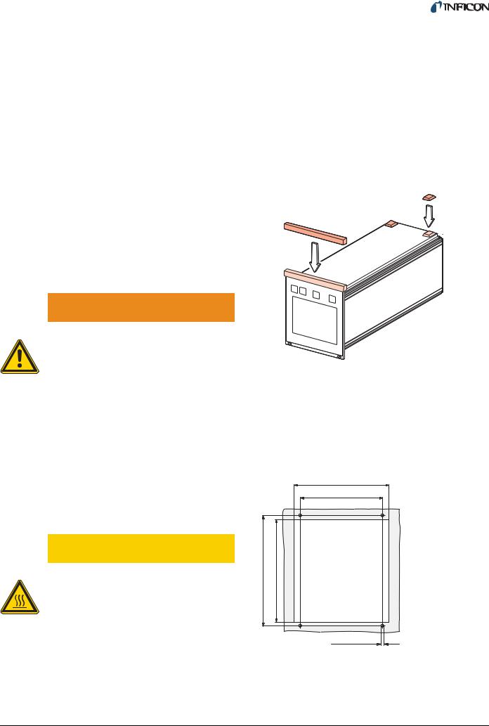
3.2.2Control panel mounted
In order to mount the unit in a control panel, the following cutout is required:
105 |
91.4 |
122.5 |
112 |
M3 (ø3.5)
Fig. 3-2 Control panel cutout (in mm)
1Insert the Vacuum Gauge Controller into the cutout
2Fasten the unit with four M3 screws
10 |
tinb07e1-e 2011-07 Vacuum Gauge Controller |

NOTE:
In order to reduce the strain on the front panel it is recommended to support the bottom of the unit.
3.2.3Mounting the unit in a rack
The Vacuum Gauge Controller is designed for installation into a rack chassis adapter according to DIN 41 494 (19", 3 HE). For this purpose, 4 collar screws and 4 plastic sleeves are supplied with the unit.
 WARNING
Lower protection class of the rack.
If the product is installed in a rack, it is likely to lower the protection class of the rack (protection from foreign bodies and water) e.g. according to the EN 60204-1 regulations for switching cabinets.
Take appropriate measures to restore the required protection class of the rack.
Fig. 3-3 Mounting the unit in a rack
NOTE:
In order to reduce the strain on the front panel it is recommended to equip the rack chassis adapter with a guide rail.
NOTE:
For safe and easy installation of heavy rack chassis adapters, it is recommended to equip the rack frame with slide rails.
1Fasten the rack chassis adapter in the rack
2Insert the Vacuum Gauge Controller into the rack chassis adapter
3Fasten the Vacuum Gauge Controller with the supplied collar screws and plastic sleeves to the rack chassis adapter
3.3 Connecting
3.3.1Back side of the device
Fig. 3-4, 11 shows the back side of the VGC403. The connection for channel 3 (Pos. C) is not available in the VGC402.
|
|
|
|
A |
J |
|
|
|
|
I |
|
|
|
B |
|
|
|
|
|
|
|
|
|
C |
|
|
|
|
D |
H |
G |
K |
F |
E |
Fig. 3-4 Back side of the VGC403
ASensor connection, channel 1
BSensor connection, channel 2
CSensor connection, channel 3
DCONTROL connection
ESwitch for program transfer mode
FRS232C connection
GMains connection / disconnecting device
HMains switch
IGround screw
JRELAY connection
KScrew for internal protective conductor. Do not loosen this screw!
 WARNING
Screw for internal protective conductor.
The internal protective conductor is connected to the casing with a screw (Pos. K).
Do not turn or loosen this screw.
The configuration of the available connections is described in the following sections.
tinb07e1-e 2011-07 Vacuum Gauge Controller |
11 |

3.3.2Mains connection
The mains connection (Fig. 3-4, 11, Pos. G) is designed for a mains cable which contains a European appliance connector on the device side.
A mains cable is supplied with the unit. If the plug is not compatible with your wall socket, you have to get a suitable mains cable:
•Three-conductor cable with protective ground
•Conductor cross-section 3 × 1.5 mm2 or larger
3.3.3Ground
The ground screw (Fig. 3-4, 11, Pos. I) can be used to connect the Vacuum Gauge Controller with the protective ground of the pumping station.
1If required: Connect the protective ground of the pumping station with the ground screw. Use a protective conductor.
3.3.4SENSOR
The SENSOR connection is used to connect the sensors.
For each channel, there are two connections available which are connected in parallel: An 8-pin RJ45 appliance socket and a 15-pin D-Sub appliance socket. See
Fig. 3-4, 11, Pos. A…C.
Pin assignment
Fig. 3-5 Three-conductor cable with protective ground (example)
 WARNING
Mains power.
Improperly grounded devices can be extremely dangerous in the event of a fault.
Use three-wire mains or extension cables with protective ground only. Plug the mains cable into wall sockets with protective ground only.
 WARNING
No mains fuse.
The Vacuum Gauge Controller is not equipped with a mains fuse.
The wall socket must be protected with a fuse (max. 10 A).
1Connect the European appliance connector of the mains cord with the mains connection of the unit
2Connect the plug of the mains cable with the wall socket
NOTE:
If the unit is installed in a switching cabinet, the mains power can be supplied via a switchable central power distributor.
8 1
Fig. 3-6 SENSOR appliance socket (RJ45)
1 |
+24 VDC |
5 |
Signal-GND |
2 |
PGND |
6 |
Status |
3 |
Signal |
7 |
HV_L |
4 |
Ident |
8 |
HV_EMI |
8 1
15 |
9 |
Fig. 3-7 SENSOR appliance socket (D-Sub, 15-pin)
1 |
EMI-Status |
9 |
n.c. |
2 |
Signal |
10 |
Ident |
3 |
Status |
11 |
Supply_CDG |
4 |
HV_EMI |
12 |
Signal-GND |
5 |
PGND |
13 |
RXD |
6 |
n.c. |
14 |
TXD |
7 |
Degas |
15 |
Chassis |
8 |
Supply |
|
|
12 |
tinb07e1-e 2011-07 Vacuum Gauge Controller |
 CAUTION
Improper sensor.
Sensors which are not designed for use with the Vacuum Gauge Controller may damage the unit.
Operate the Vacuum Gauge Controller with proper sensors only. See Chapter 2.3.1 Sensor connections, 8.
 CAUTION
Multiple connection.
Only one sensor may be connected to each of the channels. Otherwise the connected sensors will be damaged.
Never connect more than one sensor per channel.
Connecting
1Channel 1: Connect the sensor with to the CH1-A or CH1-B connection. Use a shielded 1:1 cable.
2Channel 2: Connect the sensor with to the CH2-A or CH2-B connection. Use a shielded 1:1 cable.
3Channel 3: Connect the sensor with to the CH3-A or CH3-B connection. Use a shielded 1:1 cable.
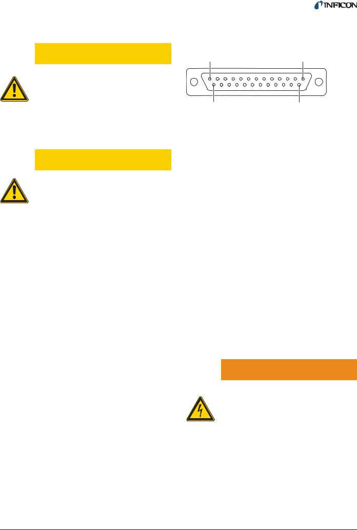
3.3.5RELAY
The switching functions and the error monitoring system influence the state of several relays inside of the Vacuum Gauge Controller. The RELAY connection (Fig. 3-4,
11, Pos. J) allows to utilize the relay contacts for switching purposes. The relay contacts are potential-free (floating).
Pin assignment
13 |
1 |
25 |
14 |
Fig. 3-8 RELAY appliance socket (D-Sub, 25-pin)
1 |
GND |
14 |
Error make contact (NO) |
2 |
n.c. |
15 |
Error common contact |
3 |
Error break contact (NC) |
|
(COM) |
4 |
SP 1 break contact (NC) |
16 |
SP 4 break contact (NC) |
5 |
SP 1 common contact |
17 |
SP 4 common contact |
(COM) |
|
(COM) |
|
6 |
SP 1 make contact (NO) |
18 |
SP 4 make contact (NO) |
7 |
GND |
19 |
SP 5 break contact (NC) |
8 |
SP 2 break contact (NC) |
20 |
SP 5 common contact |
9 |
SP 2 common contact |
|
(COM) |
(COM) |
21 |
SP 5 make contact (NO) |
|
10 |
SP 2 make contact (NO) |
22 |
SP 6 break contact (NC) |
11 |
SP 3 break contact (NC) |
23 |
SP 6 common contact |
12 |
SP 3 common contact |
|
(COM) |
(COM) |
24 |
SP 6 make contact (NO) |
|
13 |
SP 3 make contact (NO) |
25 |
+24 VDC, 200 mA. Meets |
|
|
|
the requirements of a ground |
|
|
|
protective extra low voltage |
|
|
|
(SELV) |
n.c. |
not connected |
|
|
COM common contact |
|
|
|
NC |
break contact (normally closed) |
||
NO |
make contact (normally open) |
|
|
NOTE:
Pin 25 is used for supplying relays with a higher breaking capacity. The supply contact is protected at 200 mA with a PTC element. The element is self-reset- ting when switching the unit off or unplugging the RELAY connector.
 WARNING
Hazardous voltage.
Voltages above 60 VDC or 30 VAC pose a shock hazard.
The RELAY connection may be used for switching voltages of max. 60 VDC or 30 VAC only. These voltages must meet the requirements of a ground protective extra low voltage (SELV).
1Connect the peripheral components with the RELAY connection. Use a shielded connection cable.
tinb07e1-e 2011-07 Vacuum Gauge Controller |
13 |

3.3.6CONTROL
The CONTROL connection (Fig. 3-4, 11, Pos. D) contains the following signal pins:
•Analog outputs for the signals of the individual channels
•Recorder output. This is a programmable analog output which can be assigned to one of the three channels.
•HV-EMI. Used to switch the high-vacuum circuit of the PEG sensor on and off. The signal levels are: On = +24 V. Off = 0 V. See Reference [7].
Pin assignment
1 5
6 9
Fig. 3-9 CONTROL appliance plug (D-Sub, 9-pin)
1 |
Analog output 1 |
6 |
Analog output 2 |
2 |
Analog output 3 |
7 |
Recorder output |
3 |
GND |
8 |
GND |
4 |
HV-EMI 3 |
9 |
HV-EMI 2 |
5 |
HV-EMI 1 |
|
|
1Connect the peripheral components with the CONTROL connection. Use a shielded connection cable.
NOTE:
The analog outputs (pins 1, 2, 6) differ from the displayed values by no more than ±50 mV.
3.3.7RS232C
The RS232C serial interface (Fig. 3-4, 11, Pos. F) allows remote control of the unit via a computer or a terminal. See Chapter 6 Computer interface, 32.
In addition, the interface may be used for firmware updates. See Chapter 7.2 Program transfer mode, 45.
Pin assignment
5 1
9 6
Fig. 3-10 RS232C appliance socket (D-Sub, 9-pin)
1 |
n.c. / SUP |
6 |
DSR |
2 |
TXD |
7 |
n.c. |
3 |
RXD |
8 |
CTS |
4 |
n.c. |
9 |
GND |
5 |
GND |
|
|
1Connect the serial interface of the computer with the RS232C connection. Use a shielded cable.
NOTE:
Use a serial extension cable with a 9-pin plug and a 9-pin socket. The cable must not contain any crossed wires.
14 |
tinb07e1-e 2011-07 Vacuum Gauge Controller |
4 Operation
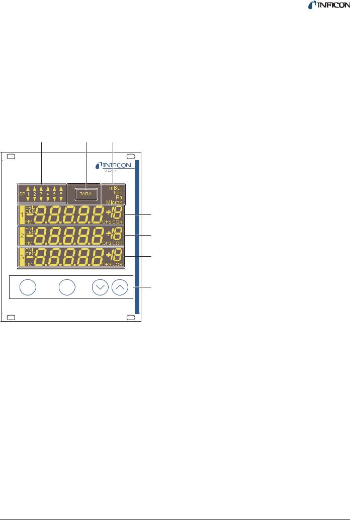
4.1 Front panel
Fig. 4-1, 15 shows the front panel of the VGC403. The VGC402 is not equipped with the switching points SP5 and SP6 (Pos. A) and the display for the channel 3 (Pos. F).
A |
B |
C |
|
|
D |
|
|
E |
|
|
F |
ch |
para |
G |
Fig. 4-1 Front panel of the VGC403
ASwitching function indicator
BParameter mode
CPressure unit
DDisplay area for channel 1
EDisplay area for channel 2
FDisplay area for channel 3
GControl buttons
4.1.1Display
Switching functions
The top left corner (Pos. A) of the display indicates the switching function states. An illuminated triangle above a number indicates that the pressure is above the lower threshold value. An illuminated triangle below a number indicates that the pressure is below the upper threshold value. See Fig. 5-1, 21.
Parameter mode
The PARA indicator (Pos. B) is illuminated when the unit is set to the parameter mode.
Pressure unit
The top right corner (Pos. C) of the display indicates the pressure unit: mbar, Torr, Pa, or Micron.
Channels
There is a separate display area for each of the available channels (Pos. D, E, F). From the left to the right, this area displays the following information:
Display |
Significance |
|
|
1, 2, 3 |
Channel number |
FAIL (flashing) |
Error |
DEG (illuminated) |
Degas function is acti- |
|
vated |
HV (illuminated) |
High-vacuum circuit is |
|
activated |
-8.8.8.8.8+18 |
Measurement or status |
|
message |
OFS (illuminated) |
Offset correction is acti- |
|
vated |
COR (illuminated) |
Gas type correction is |
|
activated |
|
|
4.1.2Control buttons
CH
The CH button is used to select a channel. This may be necessary e.g. if you want to switch a particular sensor on or off, or if you want to modify the sensor parameters. The number of the currently selected channel is flashing for a few seconds.
PARA
The PARA button is used to select the parameter mode. The PARA indicator (Pos. B) is illuminated and you can modify various parameters. See Chapter 4.5 Parameter mode, 19.
Arrow buttons (DOWN/UP)
The arrow buttons are required for entering data in the parameter mode. Pressing one of these buttons will decrease or increase the currently displayed value. In the following, these buttons will be referred to as DOWN and UP, respectively.
tinb07e1-e 2011-07 Vacuum Gauge Controller |
15 |
4.2 Switching on and off
4.2.1Switching on
1Switch the mains switch on. See Fig. 3-4, 11, Pos. H.
After switching on, the Vacuum Gauge Controller will perform the following actions:
•Self test
•Identify all sensors
•Restore the previously set parameters
•Activate measurement mode
•Adapt parameters (if a sensor type has changed meanwhile)
4.2.2Switching off
1Switch the mains switch off. See Fig. 3-4, 11, Pos. H.
4.2.3Waiting time
CAUTION
Delay time.
After switching off, the Vacuum Gauge Controller requires approximately 10 seconds to initialize again.
Wait for at least 10 seconds before you switch the Vacuum Gauge Controller on again.
NOTE:
If the Vacuum Gauge Controller has been installed in a control panel or a rack, it can also be switched on and off via the central power distributor.
4.3 Operating modes
The Vacuum Gauge Controller can be set to one of the following operating modes:
Measurement mode
The measurement mode is the standard operating mode. It displays the pressure readings of the sensors. In case of an error, a status message is displayed instead. See Chapter 4.4 Measurement mode, 17.
Parameter mode
The parameter mode gives you access to various parameters. You can check the parameter settings or modify them using the arrow buttons. This allows you to configure the Vacuum Gauge Controller. See Chapter 4.5 Parameter mode, 19.
Program transfer mode
The program transfer mode is used to transfer the latest version of the firmware to the Vacuum Gauge Controller. See Chapter 7.2 Program transfer mode, 45.
16 |
tinb07e1-e 2011-07 Vacuum Gauge Controller |
4.4 Measurement mode
4.4.1Selection
The Vacuum Gauge Controller automatically selects the measurement mode after it has been switched on.
When the unit is set to the parameter mode, it will automatically return to the measurement mode if no button is pressed for 10 seconds.
4.4.2Description
The measurement mode is the standard operating mode. It displays the pressure readings of the sensors. A status message is displayed if the pressure exceeds the permissible range. See Tab. 4-1, 17.
Display |
Pressure |
|
|
Er Hi |
Significantly above the permissible |
|
range |
|
The FAIL indicator flashes |
|
The error signal relay switches |
Reading |
In the permissible range |
Er Lo |
Significantly below the permissible |
|
range |
|
The FAIL indicator flashes |
|
The error signal relay switches |
Er x |
Error message of BPG400/HPG |
|
x = Error code (High-Byte) |
Er xx |
Error message of BCG, BPG402 |
|
xxH = Error code |
noSEn |
See Tab. 4-2, 18 |
noid |
See Tab. 4-2, 18 |
oFF |
See Tab. 5-14, 30 |
Hot |
See Chapter 5.2.6, 25 |
SELF |
See Chapter 5.2.8, 25 |
CH 1 |
See Chapter 5.2.8, 25 |
CH 2 |
See Chapter 5.2.8, 25 |
CH 3 |
See Chapter 5.2.8, 25 |
LoC |
See Chapter 5.4.5, 30 |
|
|
Tab. 4-1 Display when in measurement mode
Channels which are not connected to a sensor display noSEn. This status message disappears after approximately two minutes.
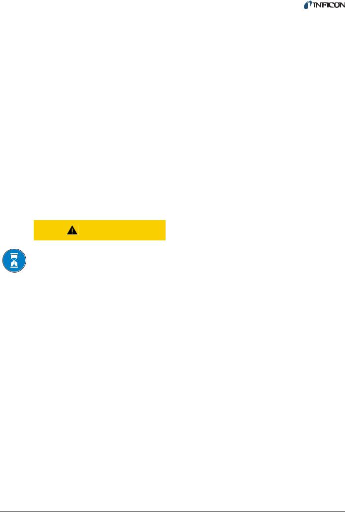
4.4.3Control button functions
4.4.3.1 Selecting a channel
1 Press the CH button
para
Fig. 4-2 Pressing the CH button
The unit selects the next channel. The number of the selected channel is flashing for a few seconds.
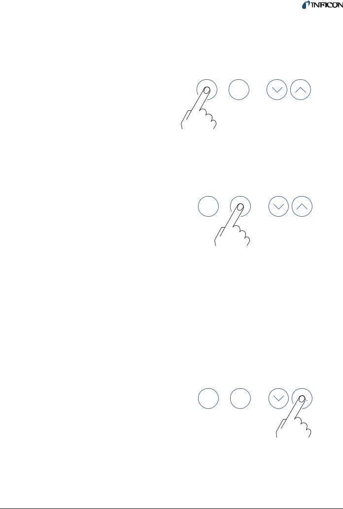
4.4.3.2 Selecting parameter mode
1 Press the PARA button
ch
Fig. 4-3 Pressing the PARA button
The unit changes to the parameter mode. See Chapter 4.5 Parameter mode, 19. It will automatically
return to the measurement mode if no button is pressed for 10 seconds.
4.4.3.3Switching high-vacuum circuit on
The high-vacuum circuit of the following sensors can be switched on manually: PEG.
For this purpose the sensor control must be set to HAnd. See Chapter 5.2.6 Sensor activation (S-on), 25.
1Press the CH button to select the required channel
2Keep the UP button pressed for approximately 1 second
ch para
Fig. 4-4 Press the UP button for 1 second
The sensor on the selected channel is switched on. The HV indicator is illuminated. The display shows the pressure reading or a status message. See Tab. 4-1, 17.
tinb07e1-e 2011-07 Vacuum Gauge Controller |
17 |
Loading...