


UL1000
Catalog-No.
from software version
TECHNICAL HANDBOOK
UL1000 Fab and
UL1000
Helium Leak Detector
UL 1000:
550 - 000A
550 - 001A
550 - 002A
UL 1000 Fab:
550 - 100A
550 - 101A
V5.14
iina70e1-m (1408) Translation of the original handbook

2
iina70e content.fm Technical Handbook(1408)

Table of Contents 3
iina70e content.fm Technical Handbook(1408)
Table of Contents
1 General Information 7
1.1 Notes on the Use of this Handbook 7
1.1.1 Safety Symbols 7
1.1.2 Indications 8
1.1.3 Symbols of Vacuum Technology 8
1.1.4 Definiton of Terms 8
1.2 Support from INFICON Service 10
1.2.1 Service Centers 11
1.3 Introduction 13
1.3.1 Purpose 13
1.3.2 Technical Data 15
1.3.2.1 Physical Data 15
1.3.2.2 Electrical Data 15
1.3.2.3 Other Data 16
1.3.2.4 Ambient Conditions 16
1.4 Unpacking 16
1.4.1 Supplied Equipment 17
1.4.2 Accessories and Options 18
1.4.2.1 Sniffer line SL200 18
1.4.2.2 Toolbox 18
1.4.2.3 Helium Bottle Holder 18
1.4.2.4 ESD Mat 18
1.4.2.5 RC1000 Remote control 19
1.4.2.6 Test chamber TC1000 20
2 Installation 21
2.1 Transportation 21
2.2 Working Location 23
2.3 Electrical Connections 25
2.3.1 Mains Power 25
2.3.2 Connections for the Data Acquisition Systems 27
2.3.2.1 Accessories 28
2.3.2.2 Digital Out 28
2.3.2.3 Digital In 29
2.3.2.4 Recorder 30
2.3.2.5 RS232 31
2.3.2.6 Remote Control 31
2.4 Vaccum Connections 32
2.4.1 Inlet Port 32
2.4.2 Exhaust 32
2.4.3 Vent 32
2.4.4 Purge-connection (UL1000 Fab) /
Gas ballast (UL1000) 32
2.5 Default parameters 33

4 Table of Contents
iina70e content.fm Technical Handbook(1408)
3 First Operation Check 34
3.1 Needed Equipment 34
3.2 Description of the Initial Operation 34
3.2.1 Start up and Measure 34
3.2.2 Internal Calibration 37
3.2.3 Verification 37
4 Description and Working Principle 38
4.1 Introduction 38
4.2 Components of the UL1000 and UL1000 Fab 38
4.2.1 Vacuum System 39
4.2.2 Control Panel 40
4.2.2.1 LC Display 41
4.2.2.2 START Button 41
4.2.2.3 STOP Button 41
4.2.2.4 ZERO Button 41
4.2.2.5 MENU Button 43
4.2.2.6 Soft Keys 43
4.2.2.7 Numerical Entries 43
4.3 Working Modes 45
4.3.1 Vacuum Mode 45
4.3.2 Sniffer Mode 47
4.3.3 Auto Leak Test Mode 47
5 Operation of the UL1000 and UL1000 Fab 48
5.1 Display 48
5.2 The Screen in Run-Up Mode 48
5.3 Display in stand-by mode 49
5.3.1 Purging 49
5.4 The Screen in Measurement Mode 49
5.4.1 Call for Calibration 49
5.4.2 Speaker Volume 50
5.4.3 Status Line in the Display 50
5.4.4 Numerical Display Mode 51
5.4.5 Trend Mode 51
6 Description of the Menu 52
6.1 Main Menu 52
6.2 View 54
6.2.1 Scale linear/logarithmic 55
6.2.2 Display-range auto/manual 55
6.2.3 Time axis 56
6.2.4 Contrast 56
6.2.5 Background in Stand-by 57
6.2.6 Decimal places 57
6.2.7 Lower display limit 58
6.3 Mode 58
6.3.1 Auto Leak Test 59

Table of Contents 5
iina70e content.fm Technical Handbook(1408)
6.4 Trigger & Alarms 61
6.4.1 Trigger Level 1 61
6.4.2 Trigger Level 2 62
6.4.3 Volume 62
6.4.4 Units 63
6.4.5 Alarm delay 63
6.4.6 Audio alarm type 64
6.4.6.1 Pinpoint 64
6.4.6.2 Leak rate prop. 64
6.4.6.3 Setpoint 65
6.4.6.4 Trigger alarm 65
6.5 Calibration 65
6.6 Settings 66
6.6.1 Vacuum settings 67
6.6.1.1 Automatic purge (UL1000 Fab only) 67
6.6.1.2 Vent delay 67
6.6.1.3 Vacuum ranges 68
6.6.1.4 Leak rate internal test leak 69
6.6.1.5 Machine factor 69
6.6.1.6 Auto Leak Test adjustments 69
6.6.2 Zero & Background 73
6.6.2.1 Background Suppression 73
6.6.2.2 Zero 73
6.6.3 Mass 74
6.6.4 Interfaces 75
6.6.4.1 Control Location 75
6.6.4.2 RS232 Protocol 76
6.6.4.3 Recorder output 77
6.6.4.4 Scaling Recorder Output 78
6.6.5 Miscellaneous 79
6.6.5.1 Time&Date 79
6.6.5.2 Language 79
6.6.5.3 Leak rate filter 80
6.6.5.4 Mains Frequency 80
6.6.5.5 Service interval exhaust filter 80
6.6.5.6 Service message exhaust filter 81
6.6.6 Parameter save / load 81
6.6.6.1 Load parameter set 81
6.6.6.2 Save parameter set 82
6.6.7 Monitoring functions 82
6.7 Information 85
6.7.1 Service 85
6.8 Access Control 86
6.8.1 Access to CAL function 86
6.8.2 Access to Trigger&Alarme menu 87
6.8.3 Change Device PIN 87
6.8.4 Change Menu-PIN 87
7 Calibration 88
7.1 Introduction 88

6 Table of Contents
iina70e content.fm Technical Handbook(1408)
7.2 The calibration routines 88
7.2.1 Internal Calibration 89
7.2.1.1 Automatic Internal Calibration 89
7.2.1.2 Manual Internal Calibration 89
7.2.2 External Calibration 89
7.3 Factor of Calibration - Range of Values 93
8 Error And Warning Messages 94
8.1 Hints 94
8.2 List of Errors & Warnings 95
9 Maintenance Work 99
9.1 General Information 99
9.2 Maintenance or Service at INFICON 100
9.3 Key to the Maintenance Plan 100
9.4 Maintenance Plan 101
9.5 Maintenance Groups 102
9.5.1 1500 Hours Maintenance 102
9.5.2 4000 Hours Maintenance 102
9.5.3 8000 Hours Maintenance 103
9.5.4 16000 Hours Maintenance 103
9.5.5 Notes refering the maintenance of the SplitFlow 80 104
9.6 Description of the Maintenance Work 104
9.6.1 Opening the Instrument for Maintenance Purposes 105
9.7 Checking and Replacing the Filter Insert 106
9.8 Replacing the Exhaust Silencer 108
9.9 Checking/Emptying the Exhaust Filter 109
9.9.1 Replacing the Filter Insert 109
9.10 Monitoring the Oil Level of the D16 B and Topping up the Oil 111
9.11 Oil Change for the D16B 112
9.12 Scroll Pumps (UL1000 and UL1000 Fab only) 114
Appendix 115
A Diagram 115
B Index 116
C Declaration of Conformity 118
General Information 7
iina70e 01.fm technical handbook(1408)
1 General Information
Notice: We recommend that you carefully read this technical handbook to ensure
optimum operating conditions right from the start.
This technical handbook contains important informations on the functions,
installation, start-up and operation of th e UL 10 00 and UL1 0 00 Fa b.
General
We reserve the right to modify the design and the specified data. The illustrations are
not binding.
1.1 Notes on the Use of this Handbook
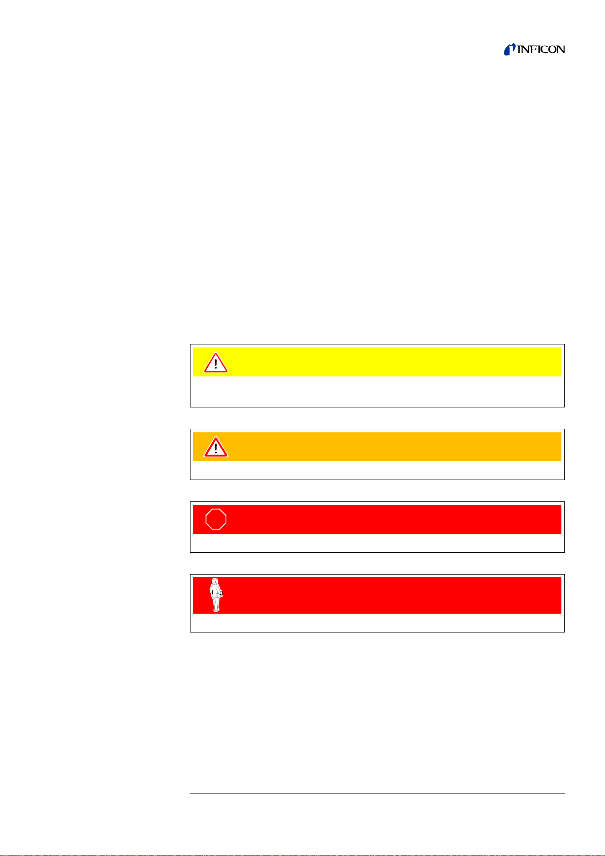
1.1.1 Safety Symbols
Important remarks concerning operational safety and protection are emphasised as
follows:
Caution
Information on correct handling or use. Disregard can lead to malfunctions or minor
equipment damage.
Warning
Information on preventing extensive equipment and environmental damage.
STO P
Danger
Information on preventing any kind of physical injury.
Skilled personnel
Indicates procedures that must be performed by skilled personnel only.
8 General Information
iina70e 01.fm technical handbook(1408)
1.1.2 Indications
Tipp Information on helpful procedures.
Notice: Information on special technical requirements that the user must comply
with.
The references to diagrams consists of the chapter number, figure number and the
item number in this order. F or example : Fig. 2-4/ 7 refers to item 7 in t he figure 4 of
chapter 2.
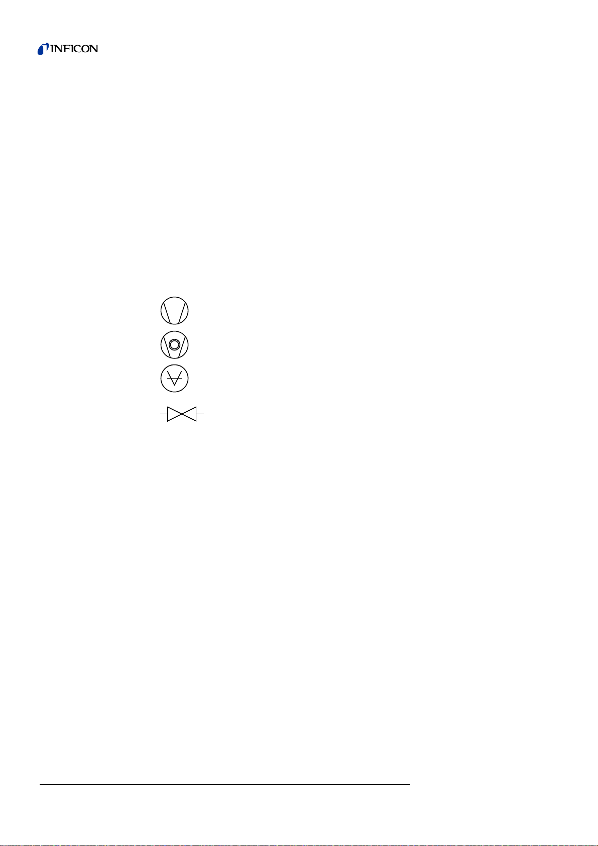
1.1.3 Symbols of Vacuum Technology
Given in the following are some important vacuum symbols which are used in this
manual.
Vacuum pump in general
Turbomolecular pump
Measuring instrument
Valve
1.1.4 Definiton of Terms
Autoranging
The range of the preamplifier and the vacuum ranges are selected automatically.
The autoranging feature of the UL1000 Fab covers the entire range or leak rates
depending on the selected operating mode. Not only the leak rate signal, but also the
pressure in the test sample (inlet pressure P1) and the forevacuum pressure (P2) are
used for control purposes. Range switching between the main ranges is performed
via valves. Fine range switching within the m ain ranges is implemen ted by switching
over the gain factor of the preamplifier.
Autotune
Mass alignment
This function automatically aligns the mass spectrometer so that a maximum leak
rate is displayed. The control processor changes the voltage which erates the ions
in the selected mass range until a maximum ion current is detected by the ion
detector. During each calibration the mass alignment is run automatically.

General Information 9
iina70e 01.fm technical handbook(1408)
Auto zero
Measurement and automatic adaptation to the helium background.
This function determines the internal ZERO level of the unit which is then deducted
from the currently measured leak rate signal. This function is enabled by pressing
the Start key provided the UL1000 or UL1000 Fab have ru n at least 20 s in "Standby"
mode or in "Ventilation" mode.
If the before suppressed helium background further decreases and only the display
limit appears, the ZERO-level will be adjusted automatically
Menu
The menu allows the user to program the UL10 00 and UL 100 0 Fab accordin g to his
requirements. The menu has a tree architecture.
Default
Status of the UL1000 and UL1000 Fab when supplie d by the fa cto ry .
GROSS
GROSS is a measurement mode which allows high inlet pressure (1 to 15 mbar).
The smallest detectable leak rate is 1x10
-6
mbar l/s.
FINE
FINE is the medium measurement mode with inlet pressure between 2 and 0,4mbar.
Detection limit is 1x10
-10
mbar l/s.
ULTRA
ULTRA is the most sensitive measuring range with inlet pressures below 0,4 mbar.
The minimum detectable leak rate is 5x10
-12
mbar l/s.
Foreline pressure
Pressure in the foreline between Turbo pump and scroll pump.
Minimum detectable leak rate
The smallest leak rate the UL1000 and UL1000 Fab is able to detect
( 5x10
-12
mbar l/s).
Internal helium background
The existing helium partial pressure in the measurement system. The level of the
internal helium background is measured in the Stand-by mode and subtracted from
the measured signal.
Measure Measurement mode
The UL1000 and UL1000 Fab measures the leak rate of the test sample.
10 General Information
iina70e 01.fm technical handbook(1408)
1.2 Support from INFICON Service
If an instrument is returned to INFICON or an authorised representative of INFICON,
please indicate wether the instrument is free of substances damaging to healths or
wether it is contaminated. If it is contaminated also indicate the nature of the hazard.
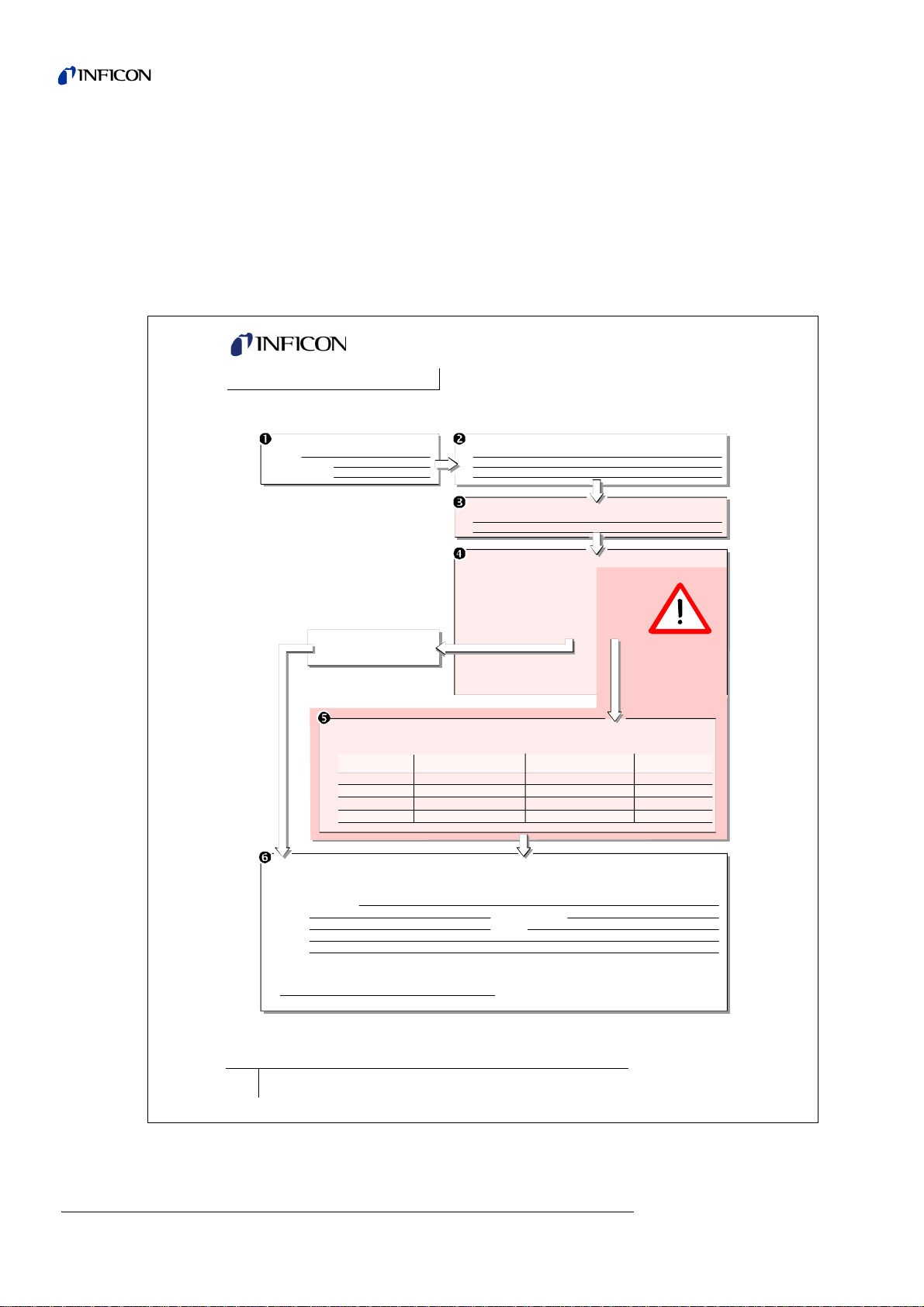
INFICON must return any appliances without a Declaration of Contamination to the
sender’s address. A form for stating details as to the type of contamination is
reproduced in Fig. 1-1.
A maintenance and service contract is recommended.
Fig. 1-1: Declaration of Contamination form
INFICON GmbH
Bonner Str. 498,50968 Cologne, Germany
Tel: +49 221 3474 2222 Fax: +49 221 3474 2221
www.inficon.com leakdetection.service
@
inficon.co
m
zisa01e1-a
Declaration of Contamination
Legally binding declaration:
I/we hereby declare that the information on this form is complete and accurate and that I/we will assume any further costs that may
arise. The contaminated product will be dispatched in accordance with the applicable regulations.
Organization/company
Address Post code, place
Phone Fax
Email
Name
Date and legally binding signature Company stamp
1) or not containing any amount
of hazardous residues that
exceed the permissible ex-
posure limits
Process related contamination of product:
toxic no
1) yes
caustic n o
1) yes
biological hazard no
yes
2)
explosive no
yes
2)
radioactive no
yes
2)
other harmful substances no
1) yes
The service, repair, and/or disposal of vacuum equipment and components will only be carried out if a correctly completed declaration has
been submitted. Non-completion will result in delay.
This declaration may only be completed (in block letters) and signed by authorized and qualified staff.
Copies:
Original for addressee - 1 copy for accompanying documents - 1 copy for file of sender
Harmful substances, gases and/or by-products
Please list all substances, gases, and by-products which the product may have come into contact with:
Trade/product name
Chemical name
(or symbol)
Precautions associated
with substance
Action if human contact
Description of product
Type
Article Number
Serial Number
Reason for return
Operating fluid(s) used (Must be drained before shipping.)
The product is free of any sub-
stances which are damaging to
health yes
This form can be downloaded
from our website.
2) Products thus contam i-
nated will not be ac-
cepted without written
evidence of deconta mi-
nation!
General Information 11
iina70e 01.fm technical handbook(1408)
1.2.1 Service Centers
In case you urgently need assistance please get in touch with the local INFICON
Service in your country or the service hotline in Cologne, Ge rm a ny:
Algeria jhj@agramkow.dk Finland jhj@agramkow.dk
Agramkow
Sonderborg
Phone: +45 741 236 36
Fax: +45 744 336 46
Agramkow
Sonderborg
Phone: +45 741 236 36
Fax: +45 744 336 46
Belarus leakdetection.service@inficon.com France Christophe.Zaffanella@oerlikon.com
INFICON GmbH
Cologne
Phone: +49 221 56788-112
Fax: +49 221 56788-9112
OLV France
Orsay
Phone: +33 476 351 584
Fax: +33 476 351 584
Belgium leakdetection.service@inficon.com Germany leakdetection.service@inficon.com
INFICON GmbH
Cologne
Phone: +49 221 56788-112
Fax: +49 221 56788-9112
INFICON GmbH
Cologne
Phone: +49 221 56788-112
Fax: +49 221 56788-9112
Brazil fernandoz@prestvacuo.com.br Hungary adam.lovics@kon-trade.hu
PV Pest Vácuo Ltda.
Santa de Parnaíba
Phone: +55 114 154 4888
Fax: +55 114 154 4888
Kontrade
Budaörs
Phone: +36 23 50 38 80
Fax: +36 23 50 38 96
Bulgaria leakdetection.service@inficon.com India asdash@hotmail.com
INFICON GmbH
Cologne
Phone: +49 221 56788-112
Fax: +49 221 56788-9112
Dashpute
400 064
Phone: +91 22 888 0324
Fax: +91 22 888 0324
Canada reachus@vpcinc.ca Ireland reach.unitedkingdom@inficon.com
Vacuum Products Canada Ltd.
Ontario
Phone: +905.672.7704
Fax: +905.672.2249
INFICON
Blackburn
Phone: +44 1254 678 250
Fax: +44 1254 698 577
Central America infoqro@meisa.com Italy davide.giovanetti@inficon.com
MEISA S.a. de C.V.
Querètaro
Phone: +52 44 22 25 42 80
Fax: +52 44 22 25 41 57
INFICON GmbH
Castelnuovo
Phone: +39 045 6 40 25 56
Fax: +39 045 6 40 24 21
China reach.china@inficon.com Israel urimark@mark-tec.co.il
INFICON LTD
Hong Kong
Phone: +852.2862.8863
Fax: +852.2865.6883
Mark Technologies Ltd.
Kiriat Ono
Phone: +972 35 34 68 22
Fax: +972 35 34 25 89
INFICON LTD
Beijing
Phone: +86.10.6590.0164
Fax: +86.10.6590.0521
Japan reach.japan@inficon.com
INFICON LTD
Guangzhou
Phone: +86.20.8723.6889
Fax: +86.20.8723.6003
INFICON Co. Ltd.
Yokohama
Phone: +81.45.471.3396
Fax: +81.45.471.3387
INFICON LTD
Shanghai
Phone: +86.21.6209.3094
Fax: +86.21.6295.2852
Czech Republic filip.lisec@inficon.com Korea reach.korea@inficon.com
INFICON GmbH
Pilsen
Phone +420 734 331 758
Fax: +420 604 203 037
INFICON Ltd.
Sungnam city
Phone: +82 312 062 890
Fax: +82 312 063 058
Denmark jhj@agramkow.dk INFICON Ltd.
Suwon City
Phone: +82 312 062 890
Fax: +82 312 063 058
Agramkow
Sonderborg
Phone: +45 744 336 36
Fax: +45 744 336 46
INFICON Ltd.
Cheonan City
Phone: +82 312 062 890
Fax: +82 312 063 058
Egypt jhj@agramkow.dk Latvia leakdetection.service@inficon.com
Agramkow
Sonderborg
Phone: +45 741 236 36
Fax: +45 744 336 46
INFICON GmbH
Cologne
Phone: +49 221 56788-112
Fax: +49 221 56788-9112
Estonia leakdetection.service@inficon.com Lithuania leakdetection.service@inficon.com
INFICON GmbH
Cologne
Phone: +49 221 56788-112
Fax: +49 221 56788-9112
INFICON GmbH
Cologne
Phone: +49 221 56788-112
Fax: +49 221 56788-9112

12 General Information
iina70e 01.fm technical handbook(1408)
Mexico infoqro@meisa.com Spain richard.cunill@leyboldoptics.com
MEISA S.a. de C.V.
Querètaro
Phone: +52 442 225 42 80
Fax: +52 442 225 41 57
Leybold Optics Ibérica
Barcelona
Phone: +34 93 66 60 778
Fax: +34 93 66 64 612
Netherlands leakdetection.service@inficon.com Sweden jhj@agramkow.dk
INFICON GmbH
Cologne
Phone: +49 221 56788-112
Fax: +49 221 56788-9112
Agramkow
Sonderborg
Phone: +45 741 236 36
Fax: +45 744 336 46
Norway jhj@agramkow.dk Syria leakdetection.service@inficon.com
Agramkow
Sonderborg
Phone: +45 741 236 36
Fax: +45 744 336 46
INFICON GmbH
Cologne
Phone: +49 221 56788-112
Fax: +49 221 56788-9112
Poland kamola@vakpol.com Taiwan Susan.Chang@inficon.com
VAK-POL & GAZ Sp. zo.o
Pulawy
Phone: +48 60 23 15 212
Fax: +48 60 23 15 212
INFICON Company Limited
Chupei City, HsinChu Hsien
Phone: +886.3.5525.828
Fax: +886.3.5525.829
Portugal leakdetection.service@inficon.com Tunisia leakdetection.service@inficon.com
INFICON GmbH
Cologne
Phone: +49 221 56788-112
Fax: +49 221 56788-9112
INFICON GmbH
Cologne
Phone: +49 221 56788-112
Fax: +49 221 56788-9112
Republic of South Africa vacuquip@hotmail.com Turkey jhj@agramkow.dk
Vacuquip
Randburg
Phone: +27 73 15 78 355 Agramkow
Sonderborg
Phone: +45 741 236 36
Fax: +45 744 336 46
Russia leakdetection.service@inficon.com Ukraine leakdetection.service@inficon.com
INFICON GmbH
Cologne
Phone: +49 221 56788-112
Fax: +49 221 56788-9112
INFICON GmbH
Cologne
Phone: +49 221 56788-112
Fax: +49 221 56788-9112
Singapore reach.singapore@inficon.com United Kingdom reach.unitedkingdom@inficon.com
INFICON PTE LTD.
Singapur
Phone: +65.890.6250
Fax: +65.890.6266
INFICON
Blackburn
Phone: +44 1254 678 250
Fax: +44 1254 698 577
Slovakia filip.lisec@inficon.com United Arab Emirates leakdetection.service@inficon.com
INFICON GmbH
Pilsen
Phone +420 734 331 758
Fax: +420 604 203 037
INFICON GmbH
Cologne
Phone: +49 221 56788-112
Fax: +49 221 56788-9112
Slovenia medivak@siol.net USA service.usa@inficon.com
Medivac
Ljubljani
Phone: +386 15 63 91 50
Fax: +386 17 22 04 51
Inficon Inc.
East Syracuse, NY
Phone: +1.315.434.1167
Fax: +1.315.434.2551
South America except Brazil infoqro@meisa.com Inficon Inc.
San Jose, CA
Phone: +1.408.361.1200
Fax: +1.408.362.1556
MEISA S.a. de C.V.
Querètaro
Phone: +52 44 22 12 36 15
Fax: +52 44 22 12 19 40
Inficon Inc.
Austin, TX
Phone: +1.512.448.0488
Fax: +1.512.448.0398
General Information 13
iina70e 01.fm technical handbook(1408)
1.3 Introduction
1.3.1 Purpose
The UL1000 and UL1000 Fab are helium leak detectors. These instruments may be
used to detect the location and the size of leaks on objects under test in two different
ways:
• when the test sample has been evacuated first and is sprayed with helium on the
outside. It is required that a vacuum connection is provided between the UL1000
and UL1000 Fab and the test sample (vacuum mode).
or
• when a helium overpressure is provided in the test sample and the test sample is
searched from the outside with a sniffer probe which is attached to the inlet port
(sniffer mode).
For UL1000 use only:
Notice: Pumping condensable gases and steams: When pumping test sample
water vapour that is inside can attain to the fore pump. With the water vapor
that is in the air - especially in humid areas or wh en using humid or wet test
samples - the acceptable compatibility of water vapor or capacity of water
vapor respectively can be exceeded.
The steam in the oil of the pump condenses when the water vapor rises over the
acceptable value. So the attribute of the oil ch anges and danger of corrosion occures
for the pump.
While using the leak detector with condensable gases and steams the oil of the fore
pump has to be controlled regularly. So you can recognize a condensation of water
vapor in the pump. Usually the oil is light and lucent. When water vapor is inside it
gets blear and milky at operating state temperature.
When turning the pump off water vapor condensates and rases the part of water in
the oil.
STO P
Danger
Caution: Danger of explosion
Hydrogen forms a highly explosive gas mixture with air.
Great caution is necessary when using hydrogen! No smoking, no naked flames,
avoid sparks.
Caution
The UL1000/UL1000 Fab is only allowed to be used as a leak detector. It ma y not
be used as a pump system (especially not for pumping off aggressive or humid
gasses)
14 General Information
iina70e 01.fm technical handbook(1408)
For UL1000 Fab use only:
If you plan to detect noxious matters please contact the manufacturer. Rules for
decontamination will be developed then. If the leak detector alreay has been in
contact with dangerous gases please fill the declaration of contamination, too, and
send it to INFICON before you send the parts.
Warning
The leak detector must not directly be switched off after the process, in which
condensable gases or steams are pumped, is finished. It must be ru nning (at least
20 minutes) with opend gas ballast valve (see Chapte r 5.3.1) until the oil of the
pump is free from detachted steams.
When not taking care of this instruction there can be a corrosion within the pump.
So damages will occure.
The height of the oil of the pump has to be controlled regularly.
The normal intervalls of changing the oil from the producer have to be taken care
of. See instructions of the rotary vane pump.
Caution
Gases that contain halogen melecules (i.e. fluorine, chlorine), i.e. refrigerants and
SF6, should not be pumped by the leak detector in higher contact rations an d over
a longer time period.
The coating layer of the cathodes (at the ion source) can be affected. This could
cause a burn out of the cathodes.
Caution
Condensable gases and steams can attain the inside of the leak detector and
destruct the fore pump.
With the water vapor that is in the air - especially in humid areas or when using
humid or wet test samples - the acceptable compatibility of water vapor or capacity
of water vapor respectively can be exceeded.
STO P
Danger
Dangerous gases pollute the machine.
So you must not use the machine for detecting toxical, acidity, microbiological,
explosive, radioactive or other noxious matters.

General Information 15
iina70e 01.fm technical handbook(1408)
1.3.2 Technical Data
1.3.2.1 Physical Data
Hinweis To get down to the minimum detected leak rate range some conditions
must be fulfilled:
• UL1000 and UL1000 Fab has fully warmed up
• Ambient conditions must be stable (temperature, no vibration/accelerations.)
• The part under test has been evacuated long enough (background is no longer
decreasing)
• ZERO must be active
1.3.2.2 Electrical Data
Max. inlet pressure 15 mbar
Minimum detectable Helium leak rates
• in vacuum mode (ULTRA) <5×10
-12
mbar l/s
limit of detection in sniffer mode <5×10
-8
mbar l/s
Maximum displayable helium leak rate in ULTRA 0.1 mbar l/s
Measurement range 12 decades
Time constant of the leak rate signal (blanked off,
63% of the final value)
<1 s
Pumping speed (Helium) at the inlet
Max. roughing capability 25 m
3
/h (50 Hz)
17.6 cfm (50 Hz)
30 m
3
/h (60 Hz)
21.1 cfm (60 Hz)
• in vacuum mode
– GROSS mode 8 l/s
– FINE mode 7 l/s
– ULTRA mode 2.5 l/s
Detectable masses 2, 3 and 4
Mass spectrometer 180° magnetic sector field
Ion source 2 filaments;
Iridium/Yttria-oxide
Inlet port DN 25 KF
Run-up time (after starting) 3 min
Part no. 550 - 000A, 550 - 100A 230 V 50 Hz
Part no. 550 - 001A, 550 - 101A 115 V 60 Hz
Part no. 550 - 00 2A 100 V 50/60 Hz
Power consumption 1100 VA
Type of protection IP20
Power cords (EU, USA, UK) 3 m

16 General Information
iina70e 01.fm technical handbook(1408)
1.3.2.3 Other Data
1.3.2.4 Ambient Conditions
1.4 Unpacking
Unpack the UL1000 and UL1000 Fab immediately after delivery, even if it will be
installed later on.
Examine the shipping container for any external damage. Completely remove the
packaging materials.
Check if the UL1000 and UL1000 Fab is complete (See Chapter 1.4.1) and carefu lly
examine the leak detector visually.
If any damage is discovered, report it immediately to the forwarding agent and
insurer. If the damaged part has to be replaced, please contact the orders
department.
Notice: Before starting up make sure that the transportation fixing is loosened.
(Please refer to chapter 2.1)
Tipp Retain the packaging materials in the event of complaints about damage.
Tipp For unpacking please use the wedge which is part of the packaging.
Valves solenoid
Dimensions (L × W × H) incl. handle in mm 1068 × 525 × 850
Dimensions (L × W × H) incl. handle in inches 42 × 21 × 33
Weight in kg 110
Weight in lbs 242
Noise level dB (A) < 70
Noise level dB (A) 0.5m distance < 56
Audio alarm dB (A) 90
Contamination level (to IEC 60664-1) 2
Overvoltage category (to IEC 60664-1) II
For use within buildings
Permissible ambient temperatur e (d ur in g op er at ion) +10 °C … +40 °C
Permissible storage temperature 0 °C … +60 °C
Max. rel. humidity 80% non condensing
Max. permissible height above sea level (during operation) 2000 m
General Information 17
iina70e 01.fm technical handbook(1408)
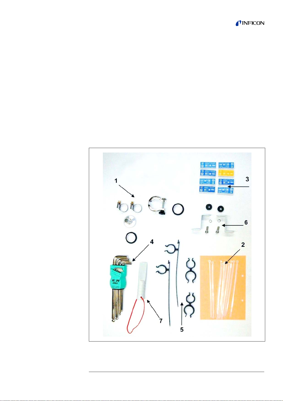
1.4.1 Supplied Equipment
• Helium Leak Detector UL1000 or UL1000 Fab
• Exhaust hose adapter with clamps (see arrow 1)
• power cord fixture
• Set of fuses (see arrow 2)
• Set of tools (see arrow 7)
• Bellow Clips (2 + 2) (see arrow 5)
• Folder with documents
– Technical Handbook UL1000 and UL1000 Fab
– Spare Parts List UL1000 and UL1000 Fab
• hooks to wrap power cord (with screws) (see arrow 6)
• Tool to open the UL1000 and UL1000 Fab (see arrow 7)
• O-Ring with filter (for use at applications with particles)
Fig. 1-2

18 General Information
iina70e 01.fm technical handbook(1408)
1.4.2 Accessories and Options
The following parts can be ordered additionally:
1.4.2.1 Sniffer line SL200
By use of the sniffer line the UL1000 and UL1000 Fab can easily be converted to a
sniffer leak detector. The length of the sniffer line is 4m (i.e. 12 feet).
1.4.2.2 Toolbox
The toolbox is a detachable compartment with a lockable lid. Fittings and small
fixtures can be stored plus the hand set (Please refer to Chapter 1.4.2.5). The
storage volume is approximately 5 l.
The toolbox is placed on the working surface and jammed by the handle.
1.4.2.3 Helium Bottle Holder
The helium bottle holder allows you to carry a helium reservoir a nd a spray g un with
the UL1000 and UL1000 Fab. Only small and midsize bottles (max 10 l, 200 bar) will
fit without influencing the stability of the UL1000 and UL1000 Fab.
1.4.2.4 ESD Mat
This mat is put on the working surface of the UL1000 and UL1000 Fab and is
clamped and grounded by the inlet port ring. It avoids electrical disch arge s between
the working surface and sensitive test parts.
• Sniffer Line SL200 14005
• Leak Ware 14090
• Helium Sniffer QUICK-TEST QT100 15594
• Tool Box (detachable) 551-000
• Helium Bottle Holder 551-001
• ESD Mat 551-002
• RC1000 Remote control
– RC1000WL wireless version
– RC1000C cable version
– Extension Cable, 8 m
551-015
551-010
14022
• Test chamber TC1000 551-005
• spray gun with hose 16555
• set of plugs 20099024
• LeakWare (software package) 14090
General Information 19
iina70e 01.fm technical handbook(1408)
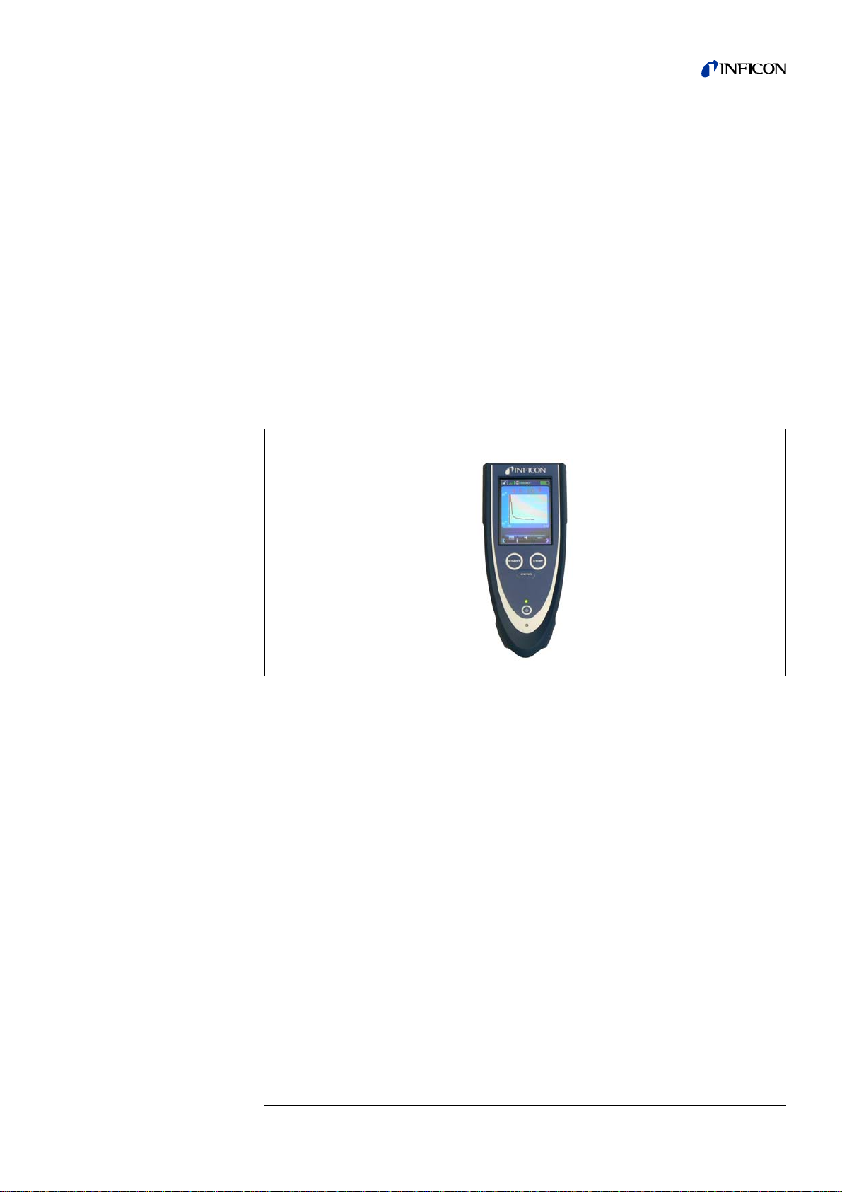
1.4.2.5 RC1000 Remote control
The RC1000 is a wireless remote control that allows to operate the UL1000 and
UL1000 Fab from distance up to 100 m. It provides the functions START, STOP/
VENT, ZERO and speaker volume, and displays leak rate in bargaraph or in chart
mode. (see also Technical Handbook RC1000.)
Measured values can be stored in an internal memory for up to 24 hours of recording
time. The data can easily be downloaded to a USB stick to save it.
An internal trigger can be set to provide a warning if the limit leak rates are exceeded.
An optical warning is shown on the display and an acoustic warning signal is
sounded on the integrated loudspeaker or the connected headphones.
The RC1000 remote control is housed in a robust housing to enable ergonomic
working. Magnets on the underside of the unit enable it to be attached to horizontal
or vertical metal surfaces.
The RC1000 also enables remote operation of the leak test device in question using
a connection cable of up to 28 metres in length.
Fig. 1-3 RC1000 wireless remote control
20 General Information
iina70e 01.fm technical handbook(1408)
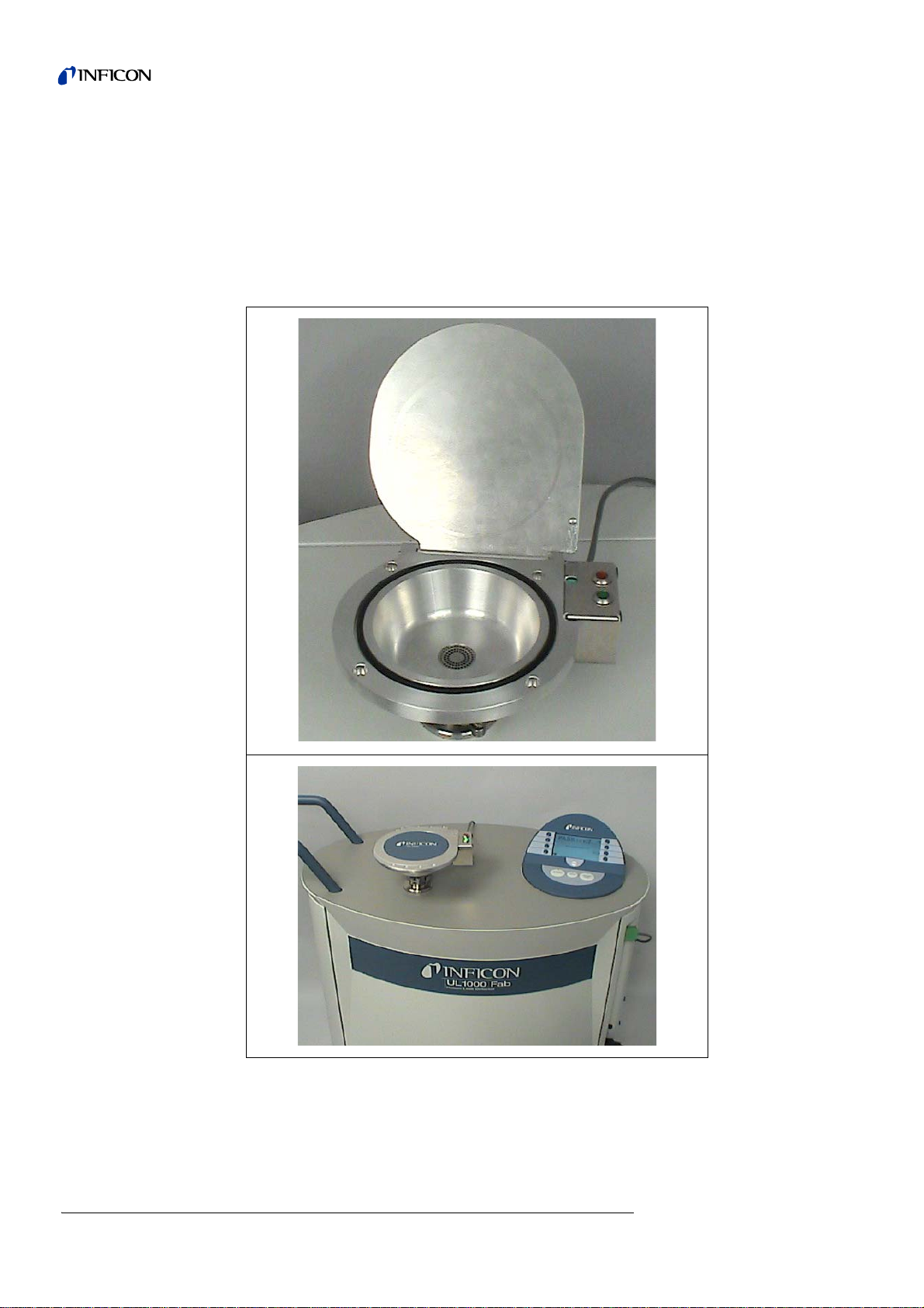
1.4.2.6 Test chamber TC1000
This test chamber turns the UL1000 / UL1000 Fab into a workstation to test
hermetically sealed components.
Testing according to MIL-STD 883 can be done easily, fast and accurate. The test
starts automatically when the chamber lid is closed, test parameters like cycle time
and rejectant level can be setted in the menu Auto Leak Test (see 6.6.1.6). The test
cycle runs automatically, the test result is also displayed by red / green LEDs directly
at the chamber.
Fig. 1-4 Test chamber TC1000
Installation 21
iina70e 02.fm technical handbook(1408)
2 Installation
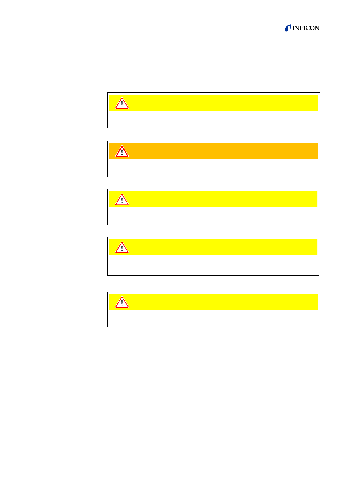
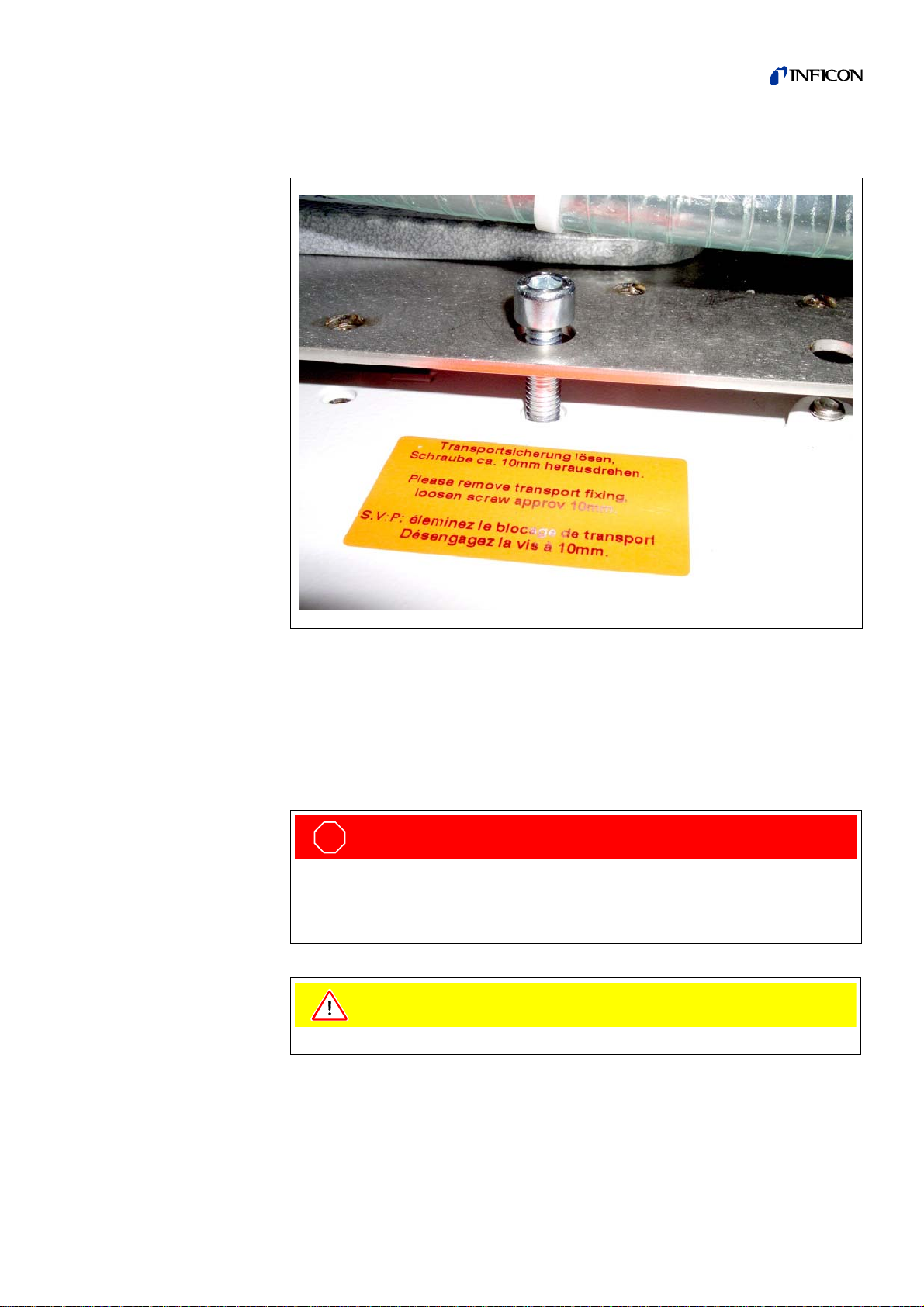
2.1 Transportation
UL1000 Fab with Triscroll TS 620
For transportation the chassis plate where the pump is mounted on has to be
secured by a transportation fixing.
This transportation fixing consists of 2 screws at chassis of the UL1000 Fab (one on
each side).
To get access to these screws remove the side covers of the UL1000 Fab.
There are orange labels on the bottom part pointing to the screws:
Caution
The UL1000 and UL1000 Fab is not equipped with any crane eyes and must
therefore not be transported using lifting equipment.
Warning
The UL1000 and UL1000 Fab must only be pushed or pulled along using the handle
provided for this purpose. Don’t use the handle to lift.
Caution
Your feet can be pinched.
Keep your feet away from the rollers. .
Caution
Your feet can be run over.
Do not pull the unit, push it
Caution
When transporting over longer distances the original pa ckaging must be used . The
castors must not be fixed when the UL1000 and UL1000 Fab is sh ipped in a crate.
22 Installation
iina70e 02.fm technical handbook(1408)
For transportation fixing the screws are tightened to the chassis plate. For oper ation
of the UL1000 Fab the screws should be loosened.
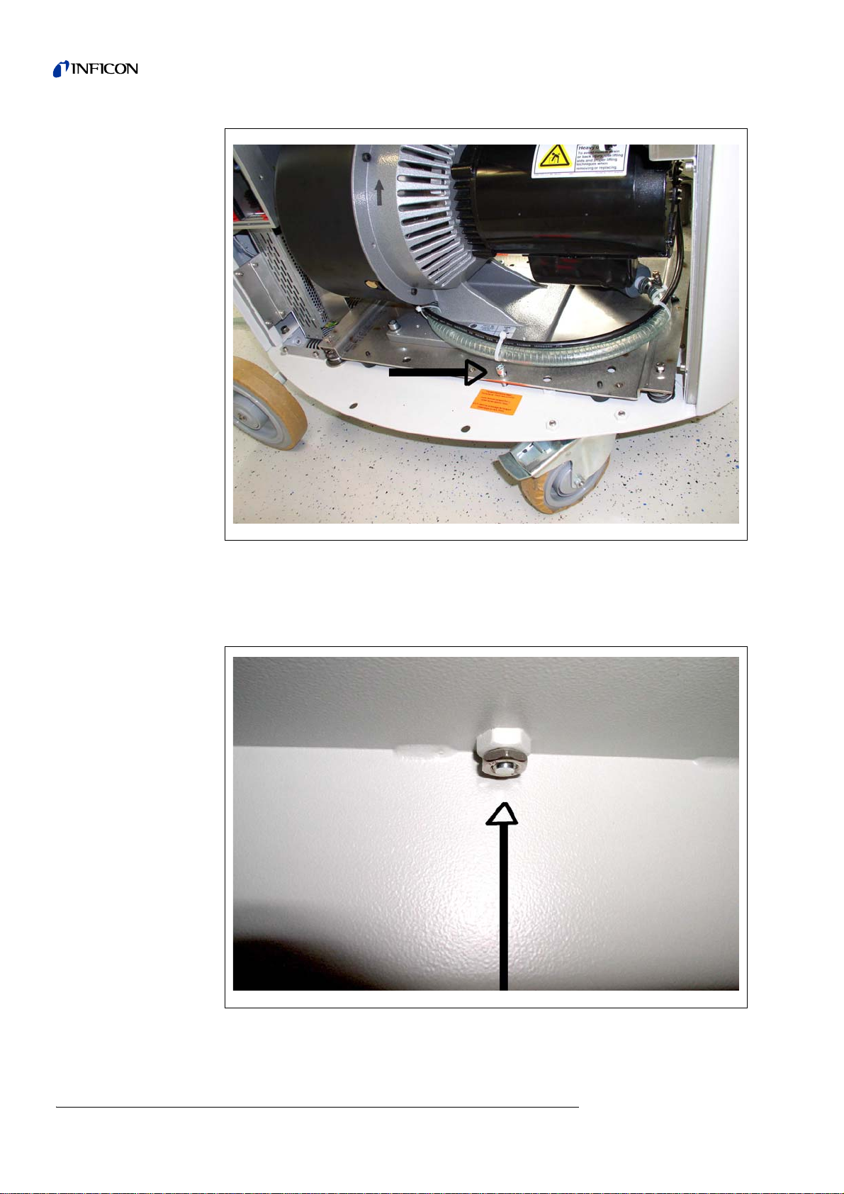
To loosen the screws first loosen the counter nut that is accessible from und erneath:
Fig. 2-1
Fig. 2-2
Installation 23
iina70e 02.fm technical handbook(1408)
Loosen the screws approximately 10 mm above the chassis plate and tighten then
the counter nuts again:
For transportation tighten the screws again and fix them by the counter nuts.
2.2 Working Location
Move the UL1000 and UL1000 Fab to the desired position and arrest the castors.
Fig. 2-3
STO P
Danger
Caution: Exhaust gases and fumes:
Exhaust gases and fumes from oil-sealed pumps may be harmful to health.
For operation in poorly ventilated rooms, an exhaust pipe should be connected to
exhaust connection 5 depending on the application and gases used.
Caution
Make sure that you can always reach the mains plug.
24 Installation
iina70e 02.fm technical handbook(1408)
It is recommended that you check all major helium sources in the vicinity of the
UL1000 and UL1000 Fab within a radius of about 10 m for the presence of any big
leaks. You may use the sniffer probe for this.
Warning
The UL1000 and UL1000 Fab must not be operated while standing in water or
when exposed to drip water. The same applies to all other kinds of liquids.
Warning
Avoid contact with bases, acids or solvents as well as exposure to extreme climatic
conditions.
Warning
The UL1000 and UL1000 Fab is designed for indoor use only.
Caution
Ensure a sufficient air cooling. The air inlet as well the air discharg e openings must
never be obstructed.
Caution
The UL1000 and UL1000 Fab can be locked by arresting the castors of the front
wheels to avoid movements on skewness.
Installation 25
iina70e 02.fm technical handbook(1408)
2.3 Electrical Connections
2.3.1 Mains Power
Notice: Generally the local regulations for electrical connections m ust be observed.
The mains voltage rating for the UL1000 and UL1000 Fab can be read off from the
name plate beneath the mains socket Fig. 2-6/7 at the back side. This vo ltage is fixed
and can not be changed.
A separate fuse for each of the mains conductors has been integ rated into the mains
switch.
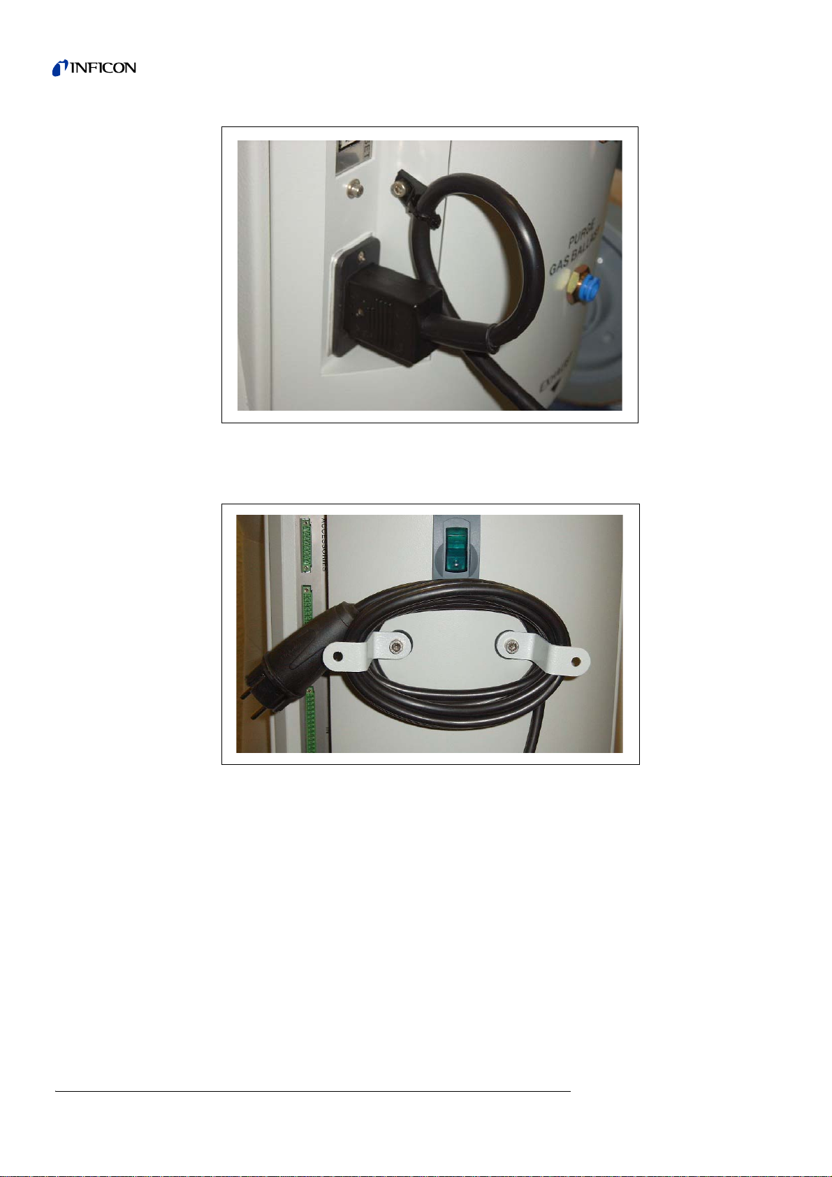
The mains voltage is applied to the instrument via the detachable mains ca ble which
is supplied with the instrument. A mains socket Fig. 2-6/7 is available for this purpose
at the back side of the instrument.
Notice: The cable can be secured like shown in the following Figure.
Warning
Before connecting the UL1000 and UL1000 Fab to the mains you mu st make sure
that the mains voltage rating of the UL1000 and UL1000 Fab coincides with the
locally available mains voltage. The instrument must exclusively be connected to a
single phase supply with fuses for installation (Circuit breaker 16A max. according
to IEC/EN 60898 with tripping characteristic B).
STO P
Danger
Caution: mains voltage:
Improperly grounded or fused products can lead to fatal injuries.
Only 3-core mains cables having a protection ground conductor must be used.
Operation of the UL1000 and UL1000 Fab where the ground conductor has been
left unconnected is not permissible.
26 Installation
iina70e 02.fm technical handbook(1408)
Notice: If the machine is not operating the cable can be stored at the cable holders.
Fig. 2-4 secure fixture power cord
Fig. 2-5 storing power cord
Installation 27
iina70e 02.fm technical handbook(1408)
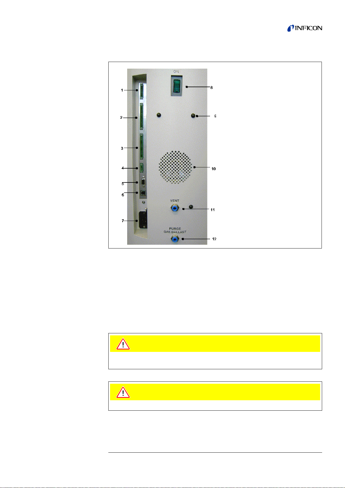
2.3.2 Connections for the Data Acquisition Systems
Tipp The sockets: Accessories, Digital Out, Digital In and Recorder have pin 1
on top. The pin numbers are counted downwards. The socket 2 and 3 are
coded mechanically to avoid a confusion with the counter plug. For the
connection with the counter plug (set of plugs 20099024) remove the
plastic pins at the plug, accordingly the plug fits the socket.
Tipp The connections for external devices are safely seperated from the mains
and safe low voltage.
1. Accessories
2. Digital Out
3. Digital In
4. Recorder
5. RS232
6. Remote Control /
Wireless transmitter
7. Mains Socket
8. Mains Switch
9. Hole to mount cable hooks.
10. Speaker
11. Vent
12. Purge (UL1000 Fab) /
Gas ballast (UL1000)
Fig. 2-6
Caution
The electronic of the device can be destroyed. So just connect de vices to the le ak
detector that are seperated from the mains.
Caution
Just connect devices that don’t excess 25V AC/Amp.

28 Installation
iina70e 02.fm technical handbook(1408)
2.3.2.1 Accessories
The following accessories may be connected to the sniffer line SL200 (P lease refe r
to Chapter Fig. 2-6/1) or the test chamber TC1000:
Contact pins 1 and 3 are fused with a 0.8 A slow-blow fuse. The amount of power
which can be drawn is limited to 10 W. The contacts are numbered from top to
bottom.
2.3.2.2 Digital Out
The following relay outputs are available for further signal processing. The maximum
rating for the relay contacts is 60V AC/1A.
Description of the operation mode of the Digital Out.
Trigger 1:
Is open in case Trigger Level 1 is exceeded or the machine is not in condition of
measuring.
Trigger 2:
Is open in case Trigger Level 2 is exceeded or the machine is not in condition of
measuring.
Zero active:
Is closed in case Zero function is running.
Ready:
Is closed in case machine is ready for measurement (Emission on, no error).
CAL active
Closed when machine is in calibrating routine.
Pin Assignment
1 +24 V, constantly applied, power supply for the sniffer line SL200.
2 GND24
3, 6 Input
4, 5, 7, 8 Output
Pin Assignment
1 +24V, bridged with pin 1 of socket „Digital In“
2 GND_24V
3 Trigger 1
4 Trigger 2
5Free
6 Zero active
7 Ready
8 CAL active
9 Cal request
10 Error
11 Warning
12 Purge
13 Measure
14 Recorder Strobe
15 Common dig. out
16 Free

Installation 29
iina70e 02.fm technical handbook(1408)
CAL Request
Is opend in case of calibration request. During external calibration a open output
indicates that the external calibrated leak has to be clos ed .
Error
Open when an error is shown.
Warning
Open when a warning is shown.
Purge
Closed when purge is active.
Measure
Closed in case a machine is in measure mode.
Recorder Strobe
Closed in case recorder output is invalid. Only used when record output is set on
„leak rate“.
2.3.2.3 Digital In
These inputs can be used to control the UL1000 and UL1000 Fab with a
programmable logic control (PLC).
Description of operation mode of the Digital In.
Zero:
Change from low to high: activate zero
Change from high to low: deactivate zero
Start:
Change from low to high: activate START
Stop:
Change from low to high: activate STOP
When this inlet is longer high than anounced in chapter 6.6.1.2 then ventilate it
additionaly.
Pin Assignment
1 +24V, bridged with pin 1 of socket „Digital Out“
2 GND_24V
3Start
4Stop
5Zero
6CAL
7 Clear
8 Purge
9Free
10 Free
11 Common dig
12 Free
13 Free
14 Free
15 Free
16 Free

30 Installation
iina70e 02.fm technical handbook(1408)
Purge:
Change from low to high: activate purge
Change from high to low: deactivate purge
Clear:
Change from low to high: confirm error message
CAL:
Change from low to high:
When machine is in stand-by mode: start internal calibration. In case machine is
measurement mode: start external calibration. (Premise: external calibration test
leak has to be open and leak rate signal is stable)
Change from high to low:
External calibration: approve that external test leak is closed and leak rate signal is
stable.
High means: U > 13 V(approximately 7mA)
Low means: U < 7 V
The level of the logic signals must not exceed 35V.
Notice: Signals at these inputs are only accepted if the location of control is set to
„PLC“ or „Local and PLC“. Refer to Chapter 6.6.4.1
2.3.2.4 Recorder
The recorder output see Fig. 2-6/4 may be used to log th e leak rate, the inlet pressure
and the forevacuum pressure.
The measured values are provided by way of an analogu e signal in the ran ge of 0 V
… 10 V. The resolution is limited to 10 mV. The instrument which is connected to the
recorder output (e. g. X(t) chart recorder) should have an input resistance of no less
than 2.5 k. The measured values are available through pins 1 and 4. The reference
potential (GND) is available at pins 2 and 3. The contacts are numbered from top to
bottom.
Tipp A diagramm showing pressures and leakrate versus voltage is attach ed in
the appendix.
Notice: The chart recorder outputs are electrically isolated from other plugs. If, in
spite of this, hum interference is apparent it is recommended to operate the
UL1000 and UL1000 Fab and the chart recorder from the same mains
phase. If this is not possible, you must make sure that the frame ground of
both instruments is kept at the same potential.
Pin Assignment
1 Analog 1
2GND
3GND
4 Analog 2
 Loading...