


 Loading...
OPERATION AND SERVICE MANUAL
MODEL MDC-360
MAXTEK FILM DEPOSITION CONTROLLER
P/N 179800
S/N _____________
MAXTEK, INC.
http://www.maxtekinc.com
5980 Lakeshore Drive, Cypress, CA 90630-3371
Tel: (714) 828-4200 • Fax: (714) 828-4443 Email: sales@maxtekinc.com • support@maxtekinc.com
©1995-2002 MAXTEK, INC. All rights reserved. First Edition, March 1995
Second Edition, Revision A, March 1996 Revision B, June 1996 Revision C, December 1996 Revision D, February 1997 Revision E, January 1998 Revision F, March 1998 Revision G, May 1998 Revision H, January 1999 Revision I, November 1999 Revision J, February 2000 Revision K, August 2000 Revision L, October 2002 Revision M, November 2002 Revision N, June 2005
ii

WARRANTY
Maxtek, Inc. warrants the product to be free of functional defects in material and workmanship and that it will perform in accordance with its published specification for a period of (twenty-four) 24 months.
The foregoing warranty is subject to the condition that the product be properly operated in accordance with instructions provided by Maxtek, Inc. or has not been subjected to improper installation or abuse, misuse, negligence, accident, corrosion, or damage during shipment.
Purchaser's sole and exclusive remedy under the above warranty is limited to, at Maxtek's option, repair or replacement of defective equipment or return to purchaser of the original purchase price. Transportation charges must be prepaid and upon examination by Maxtek the equipment must be found not to comply with the above warranty. In the event that Maxtek elects to refund the purchase price, the equipment shall be the property of Maxtek.
This warranty is in lieu of all other warranties, expressed or implied and constitutes fulfillment of all of Maxtek's liabilities to the purchaser. Maxtek does not warrant that the product can be used for any particular purpose other than that covered by the applicable specifications. Maxtek assumes no liability in any event, for consequential damages, for anticipated or lost profits, incidental damage of loss of time or other losses incurred by the purchaser or third party in connection with products covered by this warranty or otherwise.
DISCLOSURE
The disclosure of this information is to assist owners of Maxtek equipment to properly operate and maintain their equipment, and does not constitute the release of rights thereof. Reproduction of this information and equipment described herein is prohibited without prior written consent from Maxtek, Inc.,
5980 Lakeshore Drive, Cypress, California, 90630-3371.
SAFETY
All standard safety procedures associated with the safe handling of electrical equipment must be observed. Always disconnect power when working inside the controller. Only properly trained personnel should attempt to service the instrument.
iii
Table of Contents
1. |
GENERAL DESCRIPTION............................................................................................. |
1-1 |
|
1.1 |
PURPOSE....................................................................................................................... |
1-1 |
|
1.2 |
FEATURES .................................................................................................................... |
1-1 |
|
1.2.1 |
EXTENSIVE PROGRAM STORAGE ......................................................................... |
1-1 |
|
1.2.2 DYNAMIC MEASUREMENT UPDATE RATE .......................................................... |
1-1 |
||
1.2.3 |
SUPERIOR GRAPHICS DISPLAY ............................................................................ |
1-1 |
|
1.2.4 |
PROGRAM SECURITY.............................................................................................. |
1-1 |
|
1.2.5 DESIGNED FOR UNATTENDED OPERATION ...................................................... |
1-1 |
||
1.2.6 |
FAIL SAFE ABORTS.................................................................................................. |
1-1 |
|
1.2.7 |
ABORT STATUS RETENTION .................................................................................. |
1-2 |
|
1.2.8 RUN COMPLETION ON CRYSTAL FAILURE ......................................................... |
1-2 |
||
1.2.9 |
POWERFUL SYSTEM INTERFACE.......................................................................... |
1-2 |
|
1.2.10 |
POWER SUPPLY NOISE TOLERANCE............................................................... |
1-2 |
|
1.2.11 |
INTERNATIONAL STANDARD POWER CONNECTOR ..................................... |
1-2 |
|
1.2.12 |
FIELD UPGRADABLE ......................................................................................... |
1-2 |
|
1.3 |
SPECIFICATIONS......................................................................................................... |
1-3 |
|
1.3.1 |
MEASUREMENT ....................................................................................................... |
1-3 |
|
1.3.2 |
DISPLAY .................................................................................................................... |
1-3 |
|
1.3.3 |
COMMUNICATION................................................................................................... |
1-3 |
|
1.3.4 |
PROGRAM STORAGE CAPACITY ........................................................................... |
1-3 |
|
1.3.5 |
PROCESS PARAMETERS ......................................................................................... |
1-3 |
|
1.3.6 |
MATERIAL PARAMETERS ....................................................................................... |
1-3 |
|
1.3.7 |
INPUT/OUTPUT CAPABILITY ................................................................................. |
1-5 |
|
1.3.8 |
SENSOR PARAMETERS............................................................................................ |
1-5 |
|
1.3.9 |
SOURCE PARAMETERS........................................................................................... |
1-5 |
|
1.3.10 |
RECORDER PARAMETERS................................................................................. |
1-6 |
|
1.3.11 |
UTILITY SETUP PARAMETER ............................................................................ |
1-6 |
|
1.3.12 |
OTHER .................................................................................................................. |
1-6 |
|
1.4 |
ACCESSORIES.............................................................................................................. |
1-6 |
|
2. FRONT PANEL DISPLAYS AND CONTROLS ........................................................... |
2-1 |
||
2.1 |
OPERATING DISPLAYS.............................................................................................. |
2-1 |
|
2.1.1 |
|
RATE .......................................................................................................................... |
2-1 |
2.1.2 |
|
POWER ...................................................................................................................... |
2-1 |
2.1.3 |
|
THICKNESS............................................................................................................... |
2-1 |
2.1.4 |
|
LAYER NUMBER....................................................................................................... |
2-1 |
2.1.5 |
|
CRYSTAL HEALTH % ............................................................................................... |
2-1 |
2.1.6 |
|
TIME TO GO.............................................................................................................. |
2-2 |
2.2 |
PARAMETER/STATUS DISPLAYS ............................................................................ |
2-2 |
|
2.3 |
OPERATING CONTROLS............................................................................................ |
2-2 |
|
2.3.1 |
|
MANUAL KEY ........................................................................................................... |
2-2 |
2.3.2 |
|
START KEY ................................................................................................................ |
2-3 |
2.3.3 |
|
ABORT KEY............................................................................................................... |
2-3 |
2.3.4 |
|
RESET KEY................................................................................................................ |
2-3 |
2.3.5 |
|
ZERO KEY ................................................................................................................. |
2-3 |
2.3.6 |
|
SHUTTER KEY .......................................................................................................... |
2-3 |
2.3.7 |
|
STATUS KEY.............................................................................................................. |
2-3 |
2.3.8 |
|
ARROW KEYS............................................................................................................ |
2-4 |
2.3.9 |
|
PROGRAM KEY......................................................................................................... |
2-4 |
2.3.10 |
ALPHANUMERIC KEYBOARD............................................................................ |
2-5 |
|
3. BENCH CHECKOUT & INSPECTION......................................................................... |
3-1 |
|
3.1 |
INSPECTION ................................................................................................................. |
3-1 |
3.2 |
INITIAL POWER UP..................................................................................................... |
3-1 |
iv
3.3 |
SAMPLE PROGRAM.................................................................................................... |
3-1 |
|
3.3.1 |
MATERIAL #1 PARAMETERS .................................................................................. |
3-2 |
|
3.3.2 |
MATERIAL #2 PARAMETERS .................................................................................. |
3-3 |
|
3.3.3 |
PROCESS PARAMETERS ......................................................................................... |
3-4 |
|
3.4 |
SIMULATE OPERATION............................................................................................. |
3-4 |
|
3.5 |
MANUAL OPERATION ............................................................................................... |
3-4 |
|
3.6 |
INSTALLING OPTION BOARDS................................................................................ |
3-4 |
|
3.6.1 |
SOURCE-SENSOR BOARD ...................................................................................... |
3-5 |
|
3.6.2 |
DISCRETE I/O BOARD............................................................................................. |
3-5 |
|
3.6.3 |
IEEE-488 OPTION BOARD ...................................................................................... |
3-5 |
|
3.7 |
DIGITAL TO ANALOG CONVERTER (DAC) CHECKOUT..................................... |
3-5 |
|
4. PROGRAMMING AND CONTROLLER SETUP ........................................................ |
4-1 |
||
4.1 |
GENERAL...................................................................................................................... |
4-1 |
|
4.1.1 NAVIGATING THE MENU STRUCTURE ................................................................ |
4-1 |
||
4.1.2 |
ENTERING ALPHA CHARACTERS.......................................................................... |
4-2 |
|
4.1.3 |
ENTERING TIME PARAMETERS............................................................................. |
4-2 |
|
4.1.4 |
COPYING AND DELETING ..................................................................................... |
4-2 |
|
4.1.5 |
PASSWORD PROTECTION ...................................................................................... |
4-2 |
|
4.1.5.1 |
VIEW/RUN PROCESS PASSWORD ........................................................................... |
4-3 |
|
4.1.5.2 |
EDIT PROCESS PASSWORD ...................................................................................... |
4-3 |
|
4.1.5.3 |
EDIT MATERIAL PASSWORD................................................................................... |
4-3 |
|
4.1.6 ADJUSTING PARAMETER/STATUS DISPLAY CONTRAST ................................... |
4-3 |
||
4.2 |
GETTING STARTED .................................................................................................... |
4-4 |
|
4.2.1 |
UTILITY SETUP ........................................................................................................ |
4-4 |
|
4.2.2 |
DAC SETUP .............................................................................................................. |
4-4 |
|
4.2.3 |
SOURCE SETUP ....................................................................................................... |
4-4 |
|
4.2.4 |
SENSOR SETUP ........................................................................................................ |
4-7 |
|
4.2.4.1 |
EXAMPLE USING MAXTEK’S RSH-600 SIX CRYSTAL SENSOR HEAD ............ |
4-9 |
|
4.2.5 INPUT, OUTPUT AND ACTION SETUP.................................................................. |
4-9 |
||
4.2.6 |
DISPLAY SETUP...................................................................................................... |
4-10 |
|
4.2.7 |
MATERIAL SETUP................................................................................................... |
4-10 |
|
4.2.7.1 |
POWER RAMPS.......................................................................................................... |
4-11 |
|
4.2.7.2 |
AUTOMATIC CRYSTAL SWITCHING .................................................................... |
4-12 |
|
4.2.7.3 |
RATE ESTABLISH ..................................................................................................... |
4-12 |
|
4.2.7.4 |
RATE RAMPS ............................................................................................................. |
4-12 |
|
4.2.7.5 |
RATE SAMPLE MODE .............................................................................................. |
4-12 |
|
4.2.7.6 |
RATE DEVIATION ALARM...................................................................................... |
4-12 |
|
4.2.8 |
PROCESS SETUP..................................................................................................... |
4-13 |
|
4.2.9 STARTING A NEW PROCESS.................................................................................. |
4-13 |
||
4.2.10 |
RESUMING A PROCESS FROM ABORT OR HALT .......................................... |
4-13 |
|
4.3 |
DETAILED PROGRAMMING .................................................................................... |
4-13 |
|
4.3.1 |
VIEW/EDIT PROCESS ............................................................................................. |
4-13 |
|
4.3.1.1 |
DEFINE A PROCESS.................................................................................................. |
4-14 |
|
4.3.2 |
VIEW/EDIT MATERIAL ........................................................................................... |
4-16 |
|
4.3.2.1 |
DEFINE A MATERIAL............................................................................................... |
4-16 |
|
4.3.3 |
SYSTEM SETUP ....................................................................................................... |
4-23 |
|
4.3.3.1 |
EDIT DISPLAY SETUP .............................................................................................. |
4-23 |
|
4.3.3.2 |
PROGRAM INPUTS ................................................................................................... |
4-24 |
|
4.3.3.3 |
PROGRAM OUTPUTS................................................................................................ |
4-26 |
|
4.3.3.4 |
PROGRAM ACTIONS ................................................................................................ |
4-31 |
|
4.3.3.5 |
EDIT SENSOR SETUP................................................................................................ |
4-33 |
|
4.3.3.6 |
EDIT SOURCE SETUP ............................................................................................... |
4-36 |
|
4.3.3.7 |
EDIT DAC SETUP ...................................................................................................... |
4-39 |
|
4.3.3.8 |
EDIT UTILITY SETUP ............................................................................................... |
4-39 |
|
5. OPERATING THE MDC-360.......................................................................................... |
5-1 |
||
5.1 |
SIGN-ON SCREEN........................................................................................................ |
5-1 |
|
5.2 |
STARTING A NEW PROCESS .................................................................................... |
5-1 |
|
5.3 |
STARTING A NEW LAYER ........................................................................................ |
5-2 |
|
v
5.4 |
|
RESUMING AN ABORTED OR HALTED PROCESS................................................ |
5-2 |
|
5.5 |
|
STATUS DISPLAYS ..................................................................................................... |
5-3 |
|
5.6 |
|
VIEWING RESULTS..................................................................................................... |
5-4 |
|
5.7 |
|
MODES |
.......................................................................................................................... |
5-7 |
5.7.1 |
PROCESS READY...................................................................................................... |
5-7 |
||
5.7.2 |
ABORT ....................................................................................................................... |
5-7 |
||
5.7.3 |
HALT (SOFT ABORT) ............................................................................................... |
5-7 |
||
5.7.4 |
IN PROCESS.............................................................................................................. |
5-7 |
||
5.7.5 |
NOT SAMPLING........................................................................................................ |
5-7 |
||
5.7.6 |
PROCESS COMPLETE ............................................................................................. |
5-7 |
||
5.7.7 |
MANUAL.................................................................................................................... |
5-8 |
||
5.7.8 |
SIMULATE................................................................................................................. |
5-8 |
||
5.8 |
|
STATES.......................................................................................................................... |
5-8 |
|
5.9 |
|
TROUBLE, ERROR AND WARNING MESSAGES ................................................... |
5-8 |
|
5.9.1 |
DESCRIPTION .......................................................................................................... |
5-9 |
||
|
5.9.1.1 |
MIN RATE&MAX POWER.......................................................................................... |
5-9 |
|
|
5.9.1.2 |
MAX RATE&MIN POWER.......................................................................................... |
5-9 |
|
|
5.9.1.3 |
SYSTEM SETUP MEMORY CORRUPTED................................................................ |
5-9 |
|
|
5.9.1.4 |
PROCESS MEMORY CORRUPTED ........................................................................... |
5-9 |
|
|
5.9.1.5 |
MATERIAL MEMORY CORRUPTED ...................................................................... |
5-10 |
|
|
5.9.1.6 |
RATE EST. ERROR .................................................................................................... |
5-10 |
|
|
5.9.1.7 |
CRYSTAL FAILURE.................................................................................................. |
5-10 |
|
|
5.9.1.8 |
SOURCE FAULT ........................................................................................................ |
5-10 |
|
|
5.9.1.9 |
SENSOR FAULT......................................................................................................... |
5-10 |
|
|
5.9.1.10 |
TIME POWER ............................................................................................................. |
5-10 |
|
|
5.9.1.11 |
RATE DEV. ALARM.................................................................................................. |
5-10 |
|
|
5.9.1.12 |
ALARM ACTION ....................................................................................................... |
5-10 |
|
|
5.9.1.13 |
CRYSTAL MARGINAL ............................................................................................. |
5-10 |
|
|
5.9.1.14 |
RATE DEV. ALERT ................................................................................................... |
5-11 |
|
|
5.9.1.15 |
MAX POWER ALERT................................................................................................ |
5-11 |
|
|
5.9.1.16 |
MIN POWER ALERT ................................................................................................. |
5-11 |
|
|
5.9.1.17 |
ALERT ACTION......................................................................................................... |
5-11 |
|
|
5.9.1.18 |
XTAL FAIL SWITCH ................................................................................................. |
5-11 |
|
|
5.9.1.19 |
XTAL MRGN SWITCH .............................................................................................. |
5-11 |
|
|
5.9.1.20 |
RATE DEV. ATTEN ................................................................................................... |
5-11 |
|
|
5.9.1.21 |
MAXIMUM POWER .................................................................................................. |
5-11 |
|
|
5.9.1.22 |
MINIMUM POWER.................................................................................................... |
5-11 |
|
|
5.9.1.23 |
CHANGE POCKET..................................................................................................... |
5-11 |
|
|
5.9.1.24 |
CHANGE CRYSTAL... ............................................................................................... |
5-12 |
|
|
5.9.1.25 |
ATTENTION ACTION ............................................................................................... |
5-12 |
|
6. TUNING THE MDC-360 CONTROL LOOP................................................................. |
6-1 |
|||
6.1 |
|
CONTROL LOOP BASICS................................................................................................... |
6-1 |
|
6.2 |
|
CONTROL LOOPS APPLIED TO VACUUM DEPOSITION....................................................... |
6-2 |
|
6.3 |
|
ESTABLISHING MDC-360 CONTROL LOOP PARAMETERS................................................ |
6-3 |
|
7. |
INPUT/OUTPUT CHARACTERISTICS........................................................................ |
7-1 |
||
7.1 |
|
SOURCE CONTROL VOLTAGE OUTPUT................................................................. |
7-1 |
|
7.2 |
|
SENSOR INPUT ............................................................................................................ |
7-1 |
|
7.3 |
|
DISCRETE OUTPUTS................................................................................................... |
7-1 |
|
7.4 |
|
DISCRETE INPUTS....................................................................................................... |
7-1 |
|
7.5 |
|
DIGITAL-TO-ANALOG CONVERTER OUTPUTS.................................................... |
7-2 |
|
7.6 |
|
DIGITAL-TO-ANALOG CONVERTER CONTROL INPUTS .................................... |
7-2 |
|
8. |
CONTROLLER INSTALLATION ................................................................................. |
8-1 |
||
8.1 |
|
MOUNTING................................................................................................................... |
8-1 |
|
8.2 |
|
PROPER GROUNDING ................................................................................................ |
8-1 |
|
8.3 |
|
EXTERNAL CONNECTIONS ...................................................................................... |
8-1 |
|
8.3.1 |
POWER ...................................................................................................................... |
8-1 |
||
vi
8.3.2 |
|
VOLTAGE SELECTION ............................................................................................ |
8-1 |
8.3.3 |
|
GROUND LUG.......................................................................................................... |
8-2 |
8.3.4 |
|
REMOTE POWER HANDSET................................................................................... |
8-2 |
8.3.5 |
|
SOURCE-SENSOR .................................................................................................... |
8-2 |
8.3.6 |
|
RS-232 COMMUNICATION...................................................................................... |
8-2 |
8.3.7 |
|
DISCRETE INPUT/OUTPUT .................................................................................... |
8-3 |
8.3.8 |
|
DIGITAL-TO-ANALOG CONVERTER (DAC).......................................................... |
8-3 |
9. SYSTEM INSTALLATION ............................................................................................. |
9-1 |
||
9.1 |
SENSOR HEAD DESCRIPTION .................................................................................. |
9-1 |
|
9.2 |
SENSOR HEAD INSTALLATION ............................................................................... |
9-1 |
|
9.3 |
SENSOR OSCILLATOR ............................................................................................... |
9-2 |
|
9.3.1 |
|
INSTALLATION......................................................................................................... |
9-2 |
9.4 |
INSTRUMENTATION FEEDTHROUGH.................................................................... |
9-2 |
|
9.5 |
SENSOR CRYSTAL REPLACEMENT........................................................................ |
9-2 |
|
9.6 |
TYPICAL SYSTEM INSTALLATION......................................................................... |
9-3 |
|
10. |
THEORY OF OPERATION ...................................................................................... |
10-1 |
|
10.1 |
BASIC MEASUREMENT ............................................................................................ |
10-1 |
|
10.2 |
FILM THICKNESS CALCULATION.......................................................................... |
10-1 |
|
10.3 |
CRYSTAL HEALTH CALCULATION....................................................................... |
10-3 |
|
10.4 |
RATE CALCULATION................................................................................................ |
10-4 |
|
10.5 |
RATE CONTROL ......................................................................................................... |
10-4 |
|
10.6 |
EMPIRICAL CALIBRATION...................................................................................... |
10-4 |
|
10.6.1 |
FILM DENSITY.................................................................................................... |
10-4 |
|
10.6.2 |
TOOLING FACTOR............................................................................................. |
10-5 |
|
10.6.3 |
ACOUSTIC IMPEDANCE ................................................................................... |
10-5 |
|
11. |
COMPUTER INTERFACE........................................................................................ |
11-1 |
|
11.1 |
GENERAL..................................................................................................................... |
11-1 |
|
11.2 |
RS-232 SERIAL INTERFACE ..................................................................................... |
11-1 |
|
11.3 |
RS-485 SERIAL INTERFACE ..................................................................................... |
11-1 |
|
11.4 |
IEEE-488 PARALLEL INTERFACE ........................................................................... |
11-2 |
|
11.5 |
PROTOCOL .................................................................................................................. |
11-2 |
|
11.6 |
DATA TYPES............................................................................................................... |
11-3 |
|
11.7 |
MESSAGE RECEIVED STATUS................................................................................ |
11-3 |
|
11.8 |
INSTRUCTION SUMMARY ....................................................................................... |
11-4 |
|
11.9 |
INSTRUCTION DESCRIPTIONS................................................................................ |
11-5 |
|
12. |
REPAIR AND MAINTENANCE............................................................................... |
12-1 |
|
12.1 |
HANDLING PRECAUTIONS...................................................................................... |
12-1 |
|
12.2 |
MAINTENANCE PHILOSOPHY ................................................................................ |
12-1 |
|
12.3 |
TROUBLE SHOOTING AIDS ..................................................................................... |
12-2 |
|
12.4 |
RETURNING THE MDC-360 TO THE FACTORY.................................................... |
12-3 |
|
13. |
APPENDIX A............................................................................................................... |
13-1 |
|
14. |
APPENDIX B – PARAMETER TEMPLATES........................................................ |
14-2 |
|
14.1 |
MATERIAL................................................................................................................... |
14-3 |
|
14.2 |
PROCESS...................................................................................................................... |
14-5 |
|
14.3 |
DISPLAY SETUP ......................................................................................................... |
14-6 |
|
14.4 |
INPUTS ......................................................................................................................... |
14-7 |
|
14.5 |
OUTPUTS ..................................................................................................................... |
14-8 |
|
14.6 |
ACTIONS...................................................................................................................... |
14-9 |
|
14.7 |
SENSOR SETUP......................................................................................................... |
14-10 |
|
14.8 |
SOURCE SETUP ........................................................................................................ |
14-10 |
|
14.9 |
DAC SETUP................................................................................................................ |
14-11 |
|
vii
14.10 UTILITY SETUP........................................................................................................ |
14-11 |
viii
Table of Figures
FIGURE 2-1 OPERATING DISPLAY........................................................................................ |
2-1 |
FIGURE 2-2 PARAMETER/STATUS DISPLAY...................................................................... |
2-2 |
FIGURE 2-3 PROGRAMMING SECTION................................................................................ |
2-4 |
FIGURE 2-4 ARROW KEYS...................................................................................................... |
2-4 |
FIGURE 2-5 ALPHANUMERIC KEYBOARD ......................................................................... |
2-5 |
FIGURE 3-1 REMOTE POWER HANDSET ............................................................................. |
3-7 |
FIGURE 4-1 THE MAIN MENU................................................................................................ |
4-1 |
FIGURE 4-2 SELECT PROCESS SCREEN.............................................................................. |
4-14 |
FIGURE 4-3 DEFINE PROCESS SCREEN .............................................................................. |
4-14 |
FIGURE 4-4 SELECT LAYER MATERIAL SCREEN ............................................................. |
4-16 |
FIGURE 4-5 SELECT MATERIAL SCREEN............................................................................ |
4-16 |
FIGURE 4-6 DEFINE MATERIAL SCREEN............................................................................ |
4-17 |
FIGURE 4-7 SYSTEM SETUP MENU SCREEN ..................................................................... |
4-23 |
FIGURE 4-8 DISPLAY SETUP SCREEN................................................................................. |
4-23 |
FIGURE 4-9 SELECT OUTPUT SCREEN ............................................................................... |
4-27 |
FIGURE 4-10 PROGRAM OUTPUT SCREEN ........................................................................ |
4-27 |
FIGURE 4-11 SENSOR SETUP SCREEN ................................................................................ |
4-33 |
FIGURE 4-12 SOURCE SETUP SCREEN................................................................................ |
4-36 |
FIGURE 4-13 DAC SETUP SCREEN ....................................................................................... |
4-39 |
FIGURE 4-14 UTILITY SETUP SCREEN................................................................................ |
4-39 |
FIGURE 5-1 SIGN-ON SCREEN ............................................................................................... |
5-1 |
FIGURE 5-2 RUN PROCESS SELECTION SCREEN .............................................................. |
5-2 |
FIGURE 5-3 RATE VS. TIME GRAPH ..................................................................................... |
5-3 |
FIGURE 5-4 RATE DEVIATION VS. TIME GRAPH .............................................................. |
5-3 |
FIGURE 5-5 THICKNESS VS. TIME GRAPH.......................................................................... |
5-3 |
FIGURE 5-6 POWER VS. TIME GRAPH.................................................................................. |
5-4 |
FIGURE 5-7 SOURCE/SENSOR STATUS SCREEN................................................................ |
5-4 |
FIGURE 5-8 I/O STATUS SCREEN .......................................................................................... |
5-4 |
FIGURE 5-9 VIEW RESULTS SCREEN ................................................................................... |
5-6 |
FIGURE 5-10 RATE VS. TIME PROCESS LOG GRAPH........................................................ |
5-6 |
FIGURE 5-11 TYPICAL PROCESS PROFILE......................................................................... |
5-13 |
FIGURE 7-1 PASSIVE INPUT BUFFER CIRCUIT .................................................................. |
7-3 |
FIGURE 7-2 ACTIVE INPUT BUFFER CIRCUIT..................................................................... |
7-4 |
FIGURE 7-3 DAC OUTPUT CIRCUIT...................................................................................... |
7-5 |
FIGURE 7-4 SENSOR INPUT BUFFER CIRCUIT .................................................................. |
7-6 |
FIGURE 7-5 SOURCE OUTPUT DRIVER CIRCUIT............................................................... |
7-7 |
FIGURE 8-1 MDC-360 FRONT PANEL.................................................................................... |
8-4 |
FIGURE 8-2 MDC-360 REAR PANEL ...................................................................................... |
8-5 |
FIGURE 8-3 DAC SOCKET CONNECTOR PIN OUT ............................................................. |
8-6 |
FIGURE 8-4 SOURCE SOCKET CONNECTOR PIN OUT...................................................... |
8-6 |
FIGURE 8-5 D9S DTE REAR-PANEL RS-232 SOCKET CONNECTOR................................ |
8-7 |
FIGURE 8-6 D37P DISCRETE I/O PLUG CONNECTOR......................................................... |
8-8 |
FIGURE 8-7 RJ11 FRONT PANEL RS-232 CONNECTOR ..................................................... |
8-9 |
FIGURE 8-8 FRONT PANEL MANUAL POWER CONNECTOR .......................................... |
8-9 |
FIGURE 8-9 MDC-360 TOP VIEW (COVER REMOVED)..................................................... |
8-10 |
FIGURE 9-1 SENSOR OSCILLATOR SCHEMATIC............................................................... |
9-4 |
FIGURE 9-2 SENSOR OSCILLATOR OUTLINE..................................................................... |
9-5 |
FIGURE 9-3 IF-111 INSTRUMENTATION FEEDTHROUGH OUTLINE.............................. |
9-6 |
FIGURE 9-4 SH-102 SENSOR HEAD OUTLINE ..................................................................... |
9-7 |
FIGURE 9-5 TYPICAL SYSTEM INSTALLATION................................................................. |
9-8 |
FIGURE 13-1 PLUG PIN OUT - SOURCE CABLE CONNECTOR......................................... |
13-1 |
FIGURE 13-2 PLUG PIN OUT - DAC CABLE CONNECTOR................................................ |
13-2 |
FIGURE 15-1 MENU MAP ........................................................................................................ |
15-1 |
ix
List of Tables
TABLE 5-1 TROUBLE CONDITIONS AND WARNINGS ...................................................... |
5-9 |
|
TABLE 8-1 DAC SYSTEM INTERFACE CONNECTOR PIN ASSIGNMENTS .................... |
8-6 |
|
TABLE 8-2 SOURCE CONTROL SYSTEM INTERFACE CONNECTOR PIN |
|
|
ASSIGNMENTS ................................................................................................................. |
8-6 |
|
TABLE 8-3 |
D9 REAR PANEL RS-232/RS-485 CONNECTOR PIN ASSIGNMENTS............ |
8-7 |
TABLE 8-4 |
DISCRETE I/O SYSTEM INTERFACE CONNECTOR PIN ASSIGNMENTS.... |
8-8 |
TABLE 8-5 |
RJ11 FRONT PANEL RS-232 CONNECTOR PIN ASSIGNMENTS ................... |
8-9 |
TABLE 8-6 |
FRONT PANEL MANUAL POWER CONNECTOR PIN ASSIGNMENTS ........ |
8-9 |
TABLE 10-1 MATERIAL DENSITY AND ACOUSTIC IMPEDANCE VALUE ................... |
10-6 |
|
TABLE 13-1 SOURCE CONTROL CABLE COLOR CODE - (4 PIN MINI DIN)............... |
13-1 |
|
TABLE 13-2 DAC CABLE COLOR CODE - (7 PIN MINI DIN)......................................... |
13-2 |
|
x
MDC-360 DEPOSITION CONTROLLER
1.GENERAL DESCRIPTION
1.1PURPOSE
The MDC-360 provides both automatic control of single or multi-layer film deposition in either a production or development environment and improved predictability and repeatability of deposited film characteristics through dependable digital control of the deposition process. It runs unattended in the fully automatic mode and provides such features as run completion in the event of crystal failure, and extensive internal checking. Performance limits and the abort feature can be set by the user.
1.2FEATURES
The MDC-360 incorporates numerous features which are economically justifiable as a result of rapid advances in semiconductor technology and the advent of low cost microprocessors.
1.2.1EXTENSIVE PROGRAM STORAGE
The MDC-360 is capable of storing up to 99 processes, 999 layer definitions and 32 complete material definitions. Once a program is entered it will be maintained in memory for a minimum of 5 years without external power.
1.2.2DYNAMIC MEASUREMENT UPDATE RATE
Measurement is dynamically adjusted from 0.5 to 10 Hz for optimum resolution and control.
1.2.3SUPERIOR GRAPHICS DISPLAY
The MDC-360 features a 256x64 pixel LCD graphics display allowing real time graphing of important process information such as rate, rate deviation, thickness and power.
1.2.4PROGRAM SECURITY
To assure the integrity of stored programs, the MDC-360 incorporates edit passwords to guard against unauthorized program changes.
1.2.5DESIGNED FOR UNATTENDED OPERATION
The MDC-360 has been designed for truly automatic operation and toward this end incorporates extensive internal monitoring and overriding abort circuitry to minimize the possibility of damage in the event of a failure or other problem in the total deposition system. In addition there are attention, alert and alarm signals with adjustable volume for trouble and routine operator call.
1.2.6FAIL SAFE ABORTS
In the event of an MDC-360 failure, as evidenced by unsatisfactory internal checks, the MDC-360 will abort the process and shut off all outputs. In addition to the internal checks, the MDC-360 also provides user enabled aborts on excessive rate control error or crystal failure.
GENERAL DESCRIPTION 1-1

MDC-360 DEPOSITION CONTROLLER
1.2.7ABORT STATUS RETENTION
In the event that the MDC-360 does abort during the deposition process, pertinent information is stored at the time of abort. The process can be resumed after the problem is corrected.
1.2.8RUN COMPLETION ON CRYSTAL FAILURE
The extensive monitoring and abort functions are designed to protect the system and/or process from serious and hopefully infrequent malfunctions of the deposition system. A condition which need not cause an abort is the condition of crystal failure. The MDC-360 can be set to abort upon crystal failure, or run to completion using a backup crystal or time/power method.
1.2.9POWERFUL SYSTEM INTERFACE
Fully programmable discrete inputs and outputs permit the MDC-360 to be easily interfaced into deposition systems controlling the most complex processes. Also, source control outputs are fully isolated avoiding ground loop problems. The MDC-360 also supports input from an optical monitor for optical termination of film thickness.
1.2.10 POWER SUPPLY NOISE TOLERANCE
Integral RFI filter and large energy storage capacitors will tolerate high levels of power supply noise and power interruptions of 700 ms or less without effect.
1.2.11 INTERNATIONAL STANDARD POWER CONNECTOR
The power connector is internationally approved and meets IEC (International Electrotechnical Commission) standards. It allows selection of input power voltages ranging from 100 to 240 volts at a frequency of 50 or 60 Hz and includes an integral RFI filter.
1.2.12 FIELD UPGRADABLE
Plug-in interface boards and option boards allow the basic unit to be upgraded in the field to the maximum system level.
1-2 GENERAL DESCRIPTION

MDC-360 DEPOSITION CONTROLLER
1.3SPECIFICATIONS
1.3.1 |
MEASUREMENT |
|
Frequency Resolution |
0.03 Hz @6.0 MHz |
|
Mass Resolution |
0.375 ng/cm2 |
|
Thickness Accuracy |
0.5% + 1 count |
|
Measurement Update Rate |
Dynamically adjusted, 0.5 to 10 Hz |
|
Display Update Rate |
10 Hz |
|
Sensor Crystal Frequency |
2.5, 3, 5, 6, 9, 10 MHz |
|
1.3.2 |
DISPLAY |
|
|
|
|
Thickness Display |
Autoranging: 0.000 to 999.9 KÅ |
|
Rate Display |
Autoranging: 0.0 to 999 Å/sec |
|
Power Display |
0.0 to 99.9% |
|
Time To Go |
0 to 9:59:59 H:MM:SS |
|
Crystal Health % |
0 to 99% |
|
Layer Number |
1 to 999 |
|
Graphics Display |
256X64 LCD with CCFL |
|
|
|
backlighting |
1.3.3 |
COMMUNICATION |
|
|
|
|
|
|
RS-232 serial port standard |
|
|
RS-485 serial port optional |
|
|
IEEE-488 bus interface optional |
1.3.4PROGRAM STORAGE CAPACITY
Process |
99, user definable |
Layer |
999, user definable |
Material |
32, user definable |
1.3.5PROCESS PARAMETERS
Process Name |
12 character string |
Edit password |
4 character string |
Run/View password |
4 character string |
Layer# 1 to 999 |
Material name, Thickness |
1.3.6MATERIAL PARAMETERS
Material Name |
10 character string |
GENERAL DESCRIPTION 1-3

MDC-360 DEPOSITION CONTROLLER |
|
|
|
Sensor # |
1 to 4 |
Crystal # |
1 to 8 |
Source # |
1 to 4 |
Pocket # |
1 to 8 |
Material Density |
0.80 to 99.9 gm/cm3 |
Acoustic Impedance |
0.50 to 59.9 gm/cm2 sec |
Tooling Factor |
10.0 to 499.9% |
Proportional gain |
0.00 to 9999 |
Integral Time constant |
0 to 99.9 sec |
Derivative Time constant |
0 to 99.9 sec |
Rise to Soak Time |
0 to 9:59:59 H:MM:SS |
Soak Power |
0 to 99% |
Soak Time |
0 to 9:59:59 |
Rise to Predeposit Time |
0 to 9:59:59 |
Predeposit Power |
0 to 99.9% |
Predeposit Time |
0 to 9:59:59 |
Rate Establish Time |
0 to 60 sec |
Rate Establish Error |
0 to 99.9% |
Deposition Rate (1 to 5) |
00.0 to 999.9 Å/sec |
Rate Ramp Start (1 to 4) |
0.000 to 999.9 KÅ |
Rate Ramp Stop (1 to 4) |
0.000 to 999.9 KÅ |
Time Setpoint |
0 to 9:59:59 |
Ramp to Feed Time |
0 to 9:59:59 |
Feed Power |
0 to 99.9% |
Feed Time |
0 to 9:59:59 |
Ramp to Idle Time |
0 to 9:59:59 |
Idle Power |
0 to 99.9% |
Maximum Power |
0 to 99.9% |
Power Alarm Delay |
0 to 99 sec |
Minimum Power |
0 to 99.9% |
Rate Deviation Attention |
0 to 99.9% |
Rate Deviation Alarm |
0 to 99.9% |
Rate Deviation Abort |
0 to 99.9% |
Sample Dwell % |
0 to 100.0% |
Sample Period |
0 to 9:59:59 |
Crystal Fail |
Switch, Time Power, or Halt |
Backup Sensor # |
1 to 4 |
Backup Crystal # |
1 to 8 |
Backup Tooling Factor |
0 to 499.9% |
Material Password |
4 character string |
The MDC-360 also has a built in material library that contains many common material names along with their density and acoustic impedance values.
1-4 GENERAL DESCRIPTION

MDC-360 DEPOSITION CONTROLLER
1.3.7INPUT/OUTPUT CAPABILITY
Sensor Inputs |
2 Standard and 2 optional BNC inputs |
Source Outputs |
2 Standard and 2 optional fully |
|
isolated, 2.5, 5, 10 volts @ 20 ma. |
|
0.002% resolution |
Discrete Inputs |
8 Standard and 8 optional fully |
|
programmable inputs. |
|
The Passive I/O card (PN#179216) |
|
has TTL level inputs activated by a |
|
short across the input pins. |
|
The Active I/O card (PN#179239) has |
|
inputs activated by 12 to 120 volt |
|
AC/DC across the input pins. |
Discrete Outputs |
8 standard and 8 optional fully |
|
programmable, SPST relay, 120VA, |
|
2A max. |
Abort Output |
1 standard and 1 optional SPST |
|
Relay, 120VA, 2A max. |
Remote Power Handset |
Front panel, RJH jack |
RS-232 Communication |
Rear panel, 9 pin, Full duplex, DTE |
|
Front panel, RJ11 jack, Full duplex |
DAC Recorder Outputs |
Two 0 to 5 volts, 0.02% resolution |
1.3.8SENSOR PARAMETERS
Number of Crystals |
1 to 8 |
Shutter Relay Type |
Normally open, normally closed, |
|
dual, or none. |
Position Control |
Manual, direct, BCD, or individual. |
Position Drive |
Up, down, Fast, inline, single step, or |
|
double step. |
Feedback Type |
Individual, BCD, single home, in |
|
position, or no feedback. |
Rotator Delay |
0 to 99 sec |
1.3.9SOURCE PARAMETERS
Number of Pockets |
1 to 8 |
Shutter Relay Type |
Normally open, normally closed, or |
|
none. |
Shutter Delay |
0.0 to 9.9 sec |
Position Control |
Manual, direct, BCD, or individual. |
Position Drive |
Up, down, Fast, inline, single step, or |
|
double step. |
Feedback Type |
Individual, BCD, single home, in |
|
position, or no feedback. |
GENERAL DESCRIPTION 1-5

MDC-360 DEPOSITION CONTROLLER
Rotator Delay |
0 to 99 sec |
Source Voltage Range |
2.5, 5, 10 volts |
1.3.10 RECORDER PARAMETERS |
|
|
|
Recorder #1/#2 Output |
Rate, rate dev., power or thickness |
Recorder #1/#2 Scale |
Full scale %, 2/3 digit |
1.3.11 UTILITY SETUP PARAMETER |
|
|
|
Crystal Frequency |
2.5, 3, 5, 6, 9, 10 MHz |
Simulate Mode |
On/Off |
Interface Address |
1 to 32 |
Attention Volume |
0 to 10 |
Alert Volume |
0 to 10 |
Alarm Volume |
0 to 10 |
Data Points/Minute |
30,60,120,300,600 PPM |
Time |
0 to 23:59 |
Date |
MM/DD/YY |
1.3.12 OTHER |
|
|
|
Input Power Requirements |
100, 120, 200, 240 VAC; 50/60 Hz; |
|
25 watts |
Operating Temperature Range |
0 to 50°C |
Physical Weight |
10 LB |
Physical Size |
19” rackmount case |
|
3 1/2” high x 9 3/8” deep |
1.4ACCESSORIES
Part Number |
Description |
179215 |
Dual Source/Sensor Board |
179216 |
Passive I/O Board |
179217 |
IEEE-488 Communication Board |
179218 |
Internal Storage Data/Time Clock |
179219 |
RS-232 to RS-485 conversion |
179220 |
Remote Power Handset |
179239 |
Active I/O Board |
180200-4 |
DCM-200 software 3.5” diskette |
123200-5 |
SH-102 Sensor Head , cables, and |
|
carousel of 10 each 6MHz Gold SC- |
|
101 sensor crystals |
124201-4 |
SO-100 Oscillator with 6" and 10' |
|
BNC Cables. |
1-6 GENERAL DESCRIPTION

|
MDC-360 DEPOSITION CONTROLLER |
|
|
|
|
130200-2 |
|
IF-111 Instrument Feedthrough, 1" O- |
|
|
Ring with 1 electrical connector and |
|
|
dual 3/16" water tubes. |
130204-2 |
|
IF-276 Instrumentation Feedthrough, |
|
|
2 3/4" Conflat® Flange seal with 1 |
|
|
electrical connector and dual 3/16" |
|
|
water tubes. |
150902 |
|
SF-120 Combination Sensor Head, |
|
|
Feedthrough, Cables, Crystals and |
|
|
Oscillator. |
123204-1 |
|
Internal Coax Cable 30". |
123204-2 |
|
Internal Coax Cable 60". |
124202-1 |
|
BNC Cable Assembly 10'. |
124202-2 |
|
BNC Cable Assembly 20' |
124204 |
|
BNC Cable Assembly 6". |
103220 |
|
SC-101 Carousel of 10 each 6MHz |
|
|
gold sensor crystals. |
103221 |
|
SC-102 Carousel of 10 each 6MHz |
|
|
silver sensor crystals. |
Refer to Maxtek Price List for more accessories and other products.
GENERAL DESCRIPTION 1-7

MDC-360 DEPOSITION CONTROLLER
2.FRONT PANEL DISPLAYS AND CONTROLS
The front panel is divided into two sections, the operating section and the programming section. The left half of the panel is devoted to the operating displays and controls. The right half is used for programming, viewing stored processes, and displaying the status of the selected process.
2.1OPERATING DISPLAYS
All of the operating displays are updated ten times per second unless the controller is in the Abort mode. When in the Abort mode, the values of the operating displays are held constant so the operator will know the values at the time of the Abort. The controller will also flash the operating displays while in Abort to alert the operator.
Figure 2-1 Operating Display
2.1.1RATE
A three digit display with a floating decimal point is used to display deposition rate in angstroms per second at a resolution of 0.1 Å/sec from 0 to 99.9 Å/sec, and a resolution of 1.0 Å/sec for rates from 100 to 999 Å/sec.
2.1.2POWER
A three digit display with a fixed decimal point displays percent of maximum power with a resolution of 0.1% from 0 to 99.9%. This corresponds to the control voltage range of 0 to 9.99 volts.
2.1.3THICKNESS
Four digits with an autoranging decimal point display measured thickness in KÅ with a resolution of 1 Å from 0 to 9.999 KÅ, a resolution of 10 Å from 10.00 KÅ to 99.99 KÅ and a resolution of 100 Å from 100.0 KÅ to 999.9 KÅ.
2.1.4LAYER NUMBER
Three digits display the layer number of the current process.
2.1.5CRYSTAL HEALTH %
A two digit display is used to show the health percentage of the sensor crystal in use. A fresh crystal starts out with a health of 99%.
FRONT PANEL DISPLAYS AND CONTROLS 2-1
MDC-360 DEPOSITION CONTROLLER
2.1.6TIME TO GO
Time To Go is displayed in hours, minutes and seconds. This display can be configured to show the estimated state or layer time or the elapsed process, layer or state times.
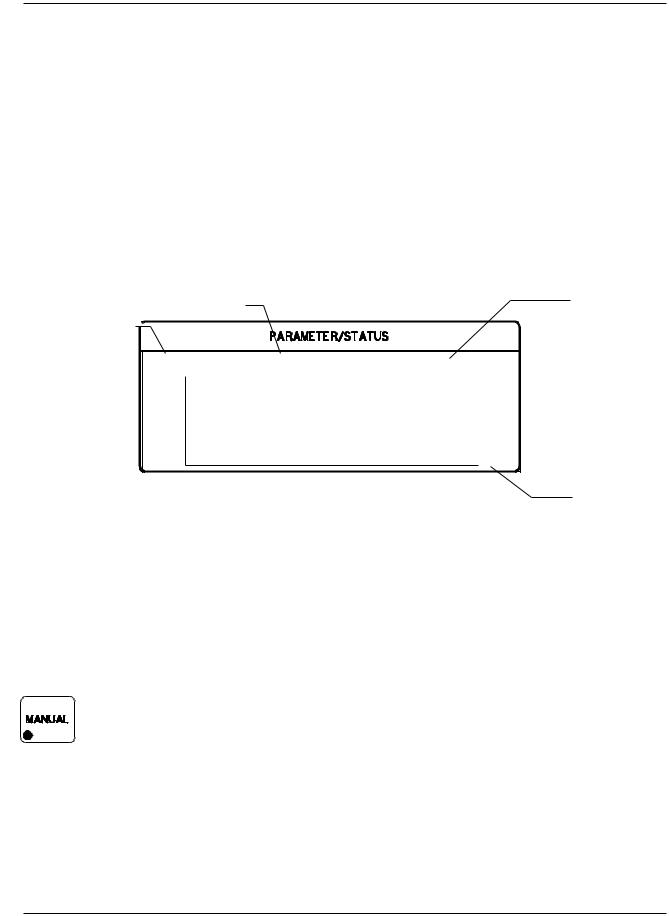
2.2PARAMETER/STATUS DISPLAYS
A graphics display labeled Parameter/Status is used for process programming and controller setup as well as displaying run time status and data graphing. The operator can switch between programming screens and status screens by pressing the Program and Status keys on the front panel. Upon power up, the Parameter/Status display automatically reverts to the last viewed status screen. Detail descriptions of the different programming and status screens can be found in Section 4 and 5.
Displays the current Displays the current material name. process name. 
Sample |
Cr |
Process Ready |
|
10 |
|
|
|
R |
|
|
|
a |
|
|
|
t |
|
|
|
e |
|
|
|
0 |
|
|
1 |
Figure 2-2 |
Parameter/Status Display |
|
|
Displays the controller modes, states or troubles.
Displays the time axis scale factor
2.3OPERATING CONTROLS
Normal operation of the MDC-360 is controlled by seven operating keys, Manual, Start, Abort, Reset, Zero, Shutter and Status. Except for the Zero and Status keys, each of the other keys is equipped with an LED to indicate the controller’s status.
2.3.1MANUAL KEY
This key is used to toggle the MDC-360 Manual mode on and off. A red light behind this key indicates the controller is in manual power control mode. This mode may be selected at any time providing that the controller is not in Abort mode. The Manual mode indicates that the source control voltage output is being controlled through the Remote Power Handset. In the Manual mode the control voltage remains constant unless incremented up or down by means of the Remote Power Handset. At entry into the Manual mode, the power is left at the last value prior to entry and is thereafter modified only through the Remote Power Handset. Exit from the manual mode is accomplished by means of the Manual or Reset key.
The MDC-360 can also be aborted through the Remote Power Handset. This abort feature is active whether or not MDC-360 is in the manual mode.
2-2 FRONT PANEL DISPLAYS AND CONTROLS
MDC-360 DEPOSITION CONTROLLER
2.3.2START KEY
The Start key starts a process, starts a layer, or resumes an aborted process. A green light behind this key indicates the controller is in process. When this key is pressed the first time a list of stored processes is displayed in the Parameter/Status window. The up and down arrow keys can be used to move the cursor to the desired process. Press the Start key again to start that process. Note that in many cases messages will be displayed in the Parameter/Status window reminding the operator to check system set up. Follow the prompt.
2.3.3ABORT KEY
The Abort key drives the MDC-360 into the Abort mode. All source powers are set to zero and discrete outputs are set to inactive state. A red light behind this key indicates the controller is in the abort mode.
2.3.4RESET KEY
The Reset key is used to clear the controller from Abort mode and put it into the Ready mode. A yellow light behind this key indicates a Ready mode. The Reset key is inactive during the In Process mode so that a premature exit from the In Process mode requires an abort.
2.3.5ZERO KEY
Pressing the Zero key causes the thickness display to go to zero. This key is active at all times and if pressed during the deposit state will result in a film thicker than that desired by an amount equal to the thickness displayed at the time the display was zeroed.
2.3.6SHUTTER KEY
This key is used to manually open and close all source shutters. The red light is illuminated when the active source shutter relay is closed. This key is only active when the controller is in the Process Ready mode.
2.3.7STATUS KEY
Pressing the Status key will bring up one of the six run-time status screens. Repeatedly pressing the key will cycle through the different status screens. Refer to Section 5 for a detailed description of these status screens.
FRONT PANEL DISPLAYS AND CONTROLS 2-3

MDC-360 DEPOSITION CONTROLLER
Figure 2-3 Programming Section
2.3.8ARROW KEYS
The arrow keys are used to navigate through the programming and setup menu structure. These keys will auto-repeat if they are held down for more than half a second.
Figure 2-4 Arrow Keys
2.3.9PROGRAM KEY
Pressing the programming key will bring up the last viewed programming screen. If a programming screen is already shown, nothing will happen. This key is also used in conjunction with the Up and Down Arrow keys to adjust the contrast of the Parameter/Status display.
2-4 FRONT PANEL DISPLAYS AND CONTROLS

MDC-360 DEPOSITION CONTROLLER
2.3.10 ALPHANUMERIC KEYBOARD
The alphanumeric keyboard is used to edit controller programs. Refer to Section 4 for the use of each key.
 ‘Backspace’
‘Enter’
Figure 2-5 Alphanumeric Keyboard
FRONT PANEL DISPLAYS AND CONTROLS 2-5

MDC-360 DEPOSITION CONTROLLER
3.BENCH CHECKOUT & INSPECTION
3.1INSPECTION
Your MDC-360 was released to the carrier in good condition and properly packed. It is essential to all concerned that the contents of the shipment be carefully examined when unpacked to assure that no damage occurred in transit. Check the material received against the packing list to be certain that all elements are accounted for. Items included with your controller are:
1 MDC-360 Deposition Controller
1 Operation and Service Manual
1 Power cord
1 Source cable (4 pin mini DIN connector)
1 Discrete I/O connector kit (37P D shell)
In addition, you may have ordered one or more of the accessories listed in Section
1.4.If there is evidence of loss or damage:
a)Notify the carrier or the carrier agent to request inspection of the loss or damage claimed.
b)Keep the shipping containers until it is determined whether or not they are needed to return the equipment to Maxtek.
3.2INITIAL POWER UP
Upon initial power up the unit will start with all LED’s lighted. The Parameter/Status display will show the controller Sign-on screen with its configuration information. The unit will stay in this state until a key is pressed.
When any key on the front panel is pressed, the operating display and the Parameter/Status display will return to the last viewed screen prior to loss of power.
3.3SAMPLE PROGRAM
The sample program listed below is included in the MDC-360 memory at the time of shipment. It can be used to check out the controller by running it in Simulate mode. Follow instructions in Section 4 to navigate through the menu structure. Check the controller parameter values against the sample program for discrepancy and change if necessary. Note also, if the source or sensor configuration has been changed during familiarization with the controller programming, appropriate source and sensor parameter values also need to be retained for the sample program to run correctly.
Once the sample program has been checked, use the programming Main Menu, Edit System Setup, Edit Utility Setup, to select Simulate mode ON, then use Start to select and run the sample program in Simulate mode.
BENCH CHECKOUT & INSPECTION 3-1

MDC-360 DEPOSITION CONTROLLER
3.3.1MATERIAL #1 PARAMETERS
Material Name |
Cr |
Sensor # |
1 |
Crystal # |
1 |
Source # |
1 |
Pocket # |
1 |
Material Density |
07.20 gm/cm3 |
Acoustic Impedance |
28.95 gm/cm2 sec |
Tooling Factor |
70 % |
Proportional gain |
2400 |
Integral Time constant |
99.9 |
Derivative Time constant |
0.00 |
Rise to Soak Time |
0:00:10 H:MM:SS |
Soak Power |
5 % |
Soak Time |
0:00:10 |
Rise to Predeposit Time |
0:00:10 |
Predeposit Power |
9.5 % |
Predeposit Time |
0:00:05 |
Rate Establish Time |
0 sec |
Rate Establish Error |
0 % |
Deposition Rate #1 |
10.0 Å/sec |
Rate Ramp Start (1 to 4) |
999.9 KÅ |
Rate Ramp Stop (1 to 4) |
999.9 KÅ |
Time Setpoint |
0 |
Ramp to Feed Time |
0:00:05 |
Feed Power |
7 % |
Feed Time |
0:00:10 |
Ramp to Idle Time |
0 |
Idle Power |
0 |
Maximum Power |
20 % |
Power Alarm Delay |
5 sec |
Minimum Power |
0 % |
Rate Deviation Attention |
0 % |
Rate Deviation Alarm |
0 % |
Rate Deviation Abort |
0 % |
Sample Dwell % |
100.0 % |
Sample Period |
0 |
Crystal Fail |
Time Power |
Backup Sensor # |
1 |
Backup Tooling Factor |
100 |
Backup Crystal # |
1 |
Material Password |
0000 |
3-2 BENCH CHECKOUT & INSPECTION

MDC-360 DEPOSITION CONTROLLER
3.3.2MATERIAL #2 PARAMETERS
Material Name |
Au |
Sensor # |
2 |
Crystal # |
1 |
Source # |
1 |
Pocket # |
2 |
Material Density |
19.30 gm/cm3 |
Acoustic Impedance |
23.18 gm/cm2 sec |
Tooling Factor |
70 % |
Proportional gain |
5000 |
Integral Time constant |
99.9 |
Derivative Time constant |
0.00 |
Rise to Soak Time |
0:00:05 H:MM:SS |
Soak Power |
25 % |
Soak Time |
0:00:05 |
Rise to Predeposit Time |
0:00:05 |
Predeposit Power |
37.5 % |
Predeposit Time |
0:00:10 |
Rate Establish Time |
0 sec |
Rate Establish Error |
0 % |
Deposition Rate #1 |
20.0 Å/sec |
Rate Ramp Start (1 to 4) |
999.9 KÅ |
Rate Ramp Stop (1 to 4) |
999.9 KÅ |
Time Setpoint |
0 |
Ramp to Feed Time |
0:00:05 |
Feed Power |
10 % |
Feed Time |
0:00:10 |
Ramp to Idle Time |
0 |
Idle Power |
0 |
Maximum Power |
50 % |
Power Alarm Delay |
5 sec |
Minimum Power |
0 % |
Rate Deviation Attention |
0 % |
Rate Deviation Alert |
0 % |
Rate Deviation Alarm |
0 % |
Sample Dwell % |
100.0 % |
Sample Period |
0 |
Crystal Fail |
Time Power |
Backup Sensor # |
1 |
Backup Tooling Factor |
100 |
Backup Crystal # |
1 |
Material Password |
0000 |
BENCH CHECKOUT & INSPECTION 3-3

MDC-360 DEPOSITION CONTROLLER
3.3.3PROCESS PARAMETERS
Process Name |
Layer No. |
Thickness |
Material |
Sample |
1 |
0.400 KÅ |
Cr |
|
2 |
1.050 KÅ |
Au |
3.4SIMULATE OPERATION
Testing the MDC-360 is best accomplished by checking its operation in the Simulate mode. This mode can be selected by using the programming Main Menu, Edit System Setup, Edit Utility Setup, to select Simulate mode ON, then use Start to select and run a process in Simulate mode.
The Simulate mode is identical to the Normal mode except that the sensor input is simulated. For this reason, entry to the Simulate mode will extinguish the Crystal Failure message if it is flashing. No other difference between the Simulate mode and the Normal mode occurs until entry to the Deposit State.
3.5MANUAL OPERATION
Manual Mode is selected by depressing the Manual key. The LED behind the key will light up indicating the controller is in Manual mode.
The Manual Mode is identical to the normal mode in all respects except that source power is controlled only through the Remote Power Handset.
The Remote Power Handset has three push buttons, see Figure 3-1. Without any of the buttons depressed, the output power is maintained at its last value. Depressing the “PWR UP” button will increase the power, depressing the “PWR DN” button will decrease the power and depressing the “ABORT” button will put the controller into the Abort mode.
The Abort Mode is active whether or not the MDC-360 is in Manual Mode and therefore can be used as a remote “panic button”.
The minimum increment by which the power is increased or decreased is 0.1%.
The Remote Power Handset can also be used to initiate a manual sensor and crystal change by depressing both the power increase and decrease buttons simultaneously. Each time a sensor/crystal switch is initiated, the controller will toggle between the primary and the backup sensor/crystal combination as defined by the active material’s parameters. The sensor/crystal switching function is only operational when the controller is not in the Manual Mode.
3.6INSTALLING OPTION BOARDS
Option boards are most easily installed while the MDC-360 is on the bench. Figure 8-9 shows the location of the various option boards. Also, they are clearly marked on the rear panel.
All Dual Source-Sensor boards are identical, as are all Discrete I/O boards. The input-output configuration of these boards is defined by the position into which
3-4 BENCH CHECKOUT & INSPECTION

MDC-360 DEPOSITION CONTROLLER
they are installed. One exception for the Discrete I/O boards is that the jumper J2 on the board installed in the Discrete I/O-2 position has to be connected. This is required so the controller will acknowledge the second Discrete I/O board. A Source-Sensor board plugged into the second position will provide sensor inputs numbers 3 & 4, and source outputs numbers 3 & 4. The IEEE-488 board has a single slot.
3.6.1SOURCE-SENSOR BOARD
1.Remove the chassis top cover.
2.Remove the three plastic hole-plugs from the rear panel.
3.Carefully slide the two BNC connectors on the Source-Sensor board into the two top holes on the rear panel. Then with even pressure, push the card edge connector down into the Main board J12.
4.Fasten the two BNC connectors using the nuts and washers supplied with the kit. Make sure the board is properly aligned.
5.Tighten the board down with the tie wrap.
6.Replace the chassis top cover and apply power to the controller.
7.The Sign On screen should acknowledge Source-Sensor 3,4 installed.
3.6.2DISCRETE I/O BOARD
1.Remove the chassis top cover.
2.Locate Discrete I/O-2 slot and remove the slot cover.
3.Carefully slide the D37 connector of the DIO board into the slot and fasten it using the hex fasteners and washers supplied with the kit.
4.Fasten the other end of the board to the standoffs using the two # 4-40 screws provided.
5.Plug the 26-pin ribbon connector into the DIO edge connector J1.
6.Replace the chassis top cover and apply power to the controller.
7.The Sign On screen should acknowledge Discrete I/O-2 installed.
3.6.3IEEE-488 OPTION BOARD
1.Remove the chassis top cover.
2.Locate IEEE-488 option slot and remove the slot cover.
3.Carefully slide the connector of the IEEE-488 board into the slot and fasten it using the fasteners and washers supplied with the kit.
4.Plug the 20-pin ribbon connector into J7 connector on the Main board.
5.Replace the chassis top cover and apply power to the controller.
6.The Sign On screen should acknowledge IEEE-488 option installed.
3.7DIGITAL TO ANALOG CONVERTER (DAC) CHECKOUT
The built-in DAC function on the Main board contains two converters, allowing simultaneous recording of any two of the following four parameters: Rate, Rate deviation, Power and Thickness. The full scale output of each converter is 5 volts, is single ended and is referenced to ground. Parameter selection for each of the channels is accomplished independently by making the appropriate choices in the DAC setup menu.
BENCH CHECKOUT & INSPECTION 3-5

MDC-360 DEPOSITION CONTROLLER
In addition to the individual channel output pins there are two control pins which are common to both channels and are intended to simplify the process of setting up analog recorders. Connecting the Zero control line to ground will drive both channel outputs to zero, allowing the recorder zero reference to be easily set. Releasing the Zero line and connecting the Full Scale line to ground will drive both channel outputs to full scale for establishing the recorder full scale calibration.
Each channel can be set independently to convert either the two or the three least significant digits of the chosen parameter to a proportional analog signal, corresponding to the DAC setup option chosen. With the three digit setting, a thickness of 0.500 KÅ would result in an analog output of 2.50 volts, or a scale factor of 5 mV/Å. If more resolution is desired, either channel can be configured to convert only the last two digits of the parameter, thus the analog output would achieve full scale at 99Å. The output scale factor in this configuration is 50 mV/Å.
The above scale factors are based on the assumption that the thickness display is in the 0 - 9.999 KÅ range. Because the thickness and rate displays are autoranging, the analog output of these variables will also autorange so that in the above example, if the thickness is in the range of 10 KÅ to 99.9 KÅ, the analog scale factor would be 50 millivolts per 10 Å, also ten times larger.
The Rate deviation parameter must be handled differently than the other parameters because it can be negative. Maximum positive error is converted to 5 volts, maximum negative error is converted to 0 volts and zero error is converted to a mid scale, 2.5 volt, output. Maximum corresponds to 99 or 999, plus 1.
The DAC can be checked by putting the MDC-360 into the Simulate mode and checking for correspondence between the analog output and the selected front panel displays.
3-6 BENCH CHECKOUT & INSPECTION
Loading...