


Translation of the original operating instructions
HLD6000
Leak detector
kina43e1-a, 1408
Order no.: |
|
510-025, 510-027, |
from software version: |
510-028 |
1.11 |

No part of this manual may be reprinted, translated or duplicated without the expressed written consent of INFICON GmbH.
Translation of the original operating instructions HLD6000, kina43e1-a, 1408
2

Translation of the original operating instructions HLD6000, kina43e1-a, 1408
Table of Contents |
|
|
1 |
About these instructions ............................................................................................................................................ |
7 |
1.1 |
Target groups ................................................................................................................................................................. |
7 |
1.2 |
Other applicable documents .................................................................................................................................... |
7 |
1.3 |
Displaying information ............................................................................................................................................... |
7 |
1.3.1 |
Warnings .......................................................................................................................................................................... |
7 |
2 |
Safety ................................................................................................................................................................................. |
9 |
2.1 |
Intended use ................................................................................................................................................................... |
9 |
2.2 |
Owner requirements .................................................................................................................................................... |
9 |
2.3 |
Operator requirements ............................................................................................................................................. |
10 |
2.4 |
Dangers .......................................................................................................................................................................... |
10 |
3 |
Shipment, Transport, Storage ................................................................................................................................ |
11 |
4 |
Description .................................................................................................................................................................... |
13 |
4.1 |
Function ......................................................................................................................................................................... |
13 |
4.2 |
Basic unit ........................................................................................................................................................................ |
14 |
4.3 |
Sniffer line ...................................................................................................................................................................... |
16 |
4.4 |
Technical data ............................................................................................................................................................... |
17 |
5 |
Installation ..................................................................................................................................................................... |
23 |
5.1 |
Setup ............................................................................................................................................................................... |
23 |
5.2 |
Sniffer line ..................................................................................................................................................................... |
23 |
5.2.1 |
Connecting the sniffer line ...................................................................................................................................... |
23 |
5.2.2 |
Exchanging the sniffer line ...................................................................................................................................... |
23 |
5.3 |
Sniffer tip ........................................................................................................................................................................ |
24 |
5.3.1 |
Replacing the sniffer tip ............................................................................................................................................ |
24 |
5.3.2 |
Using the water conservation sniffer tip ............................................................................................................ |
25 |
5.3.3 |
Use flexible sniffer tips .............................................................................................................................................. |
25 |
5.3.4 |
Using an extension hose for a sniffer tip ............................................................................................................ |
26 |
5.4 |
Insert or replace a COOL-Check calibration leak ............................................................................................. |
26 |
5.5 |
Connecting to the power supply system ........................................................................................................... |
27 |
5.6 |
Using a USB stick ......................................................................................................................................................... |
27 |
5.7 |
Connecting a PC .......................................................................................................................................................... |
27 |
6 |
Operation ....................................................................................................................................................................... |
29 |
6.1 |
Switching on the device ........................................................................................................................................... |
29 |
6.2 |
Operating the device ................................................................................................................................................. |
30 |
6.2.1 |
Structure of the touch screen ................................................................................................................................. |
30 |
6.2.2 |
Measurement display elements ............................................................................................................................. |
32 |
6.2.3 |
Display on the sniffer line ......................................................................................................................................... |
33 |
6.3 |
Basic settings ............................................................................................................................................................... |
34 |
6.3.1 |
Setting the language ................................................................................................................................................. |
34 |
6.3.2 |
Setting date and time ................................................................................................................................................ |
34 |
6.3.3 |
Adjust volume .............................................................................................................................................................. |
34 |
6.3.4 |
Setting auto standby ................................................................................................................................................. |
35 |
6.3.5 |
Setting the display ...................................................................................................................................................... |
35 |
Table of Contents |
3 |

6.3.6 |
Set time interval for calibration request ............................................................................................................. |
36 |
6.3.7 |
Switching the request for replacing filters on or off ...................................................................................... |
36 |
6.3.8 |
I/O module .................................................................................................................................................................... |
36 |
6.3.8.1 |
Create a connection between the device and the I/O module ................................................................. |
36 |
6.3.8.2 |
Configuring analog outputs ................................................................................................................................... |
37 |
6.3.8.3 |
Setting the upper scale value for 10 V of the analog output ...................................................................... |
37 |
6.3.8.4 |
Setting up the I/O module protocol .................................................................................................................... |
37 |
6.3.8.5 |
Configuring PLC outputs ......................................................................................................................................... |
37 |
6.3.8.6 |
Configuring PLC inputs ............................................................................................................................................ |
38 |
6.3.8.7 |
Setting the interface unit ......................................................................................................................................... |
38 |
6.3.9 |
Set up scope of error messages ............................................................................................................................ |
38 |
6.3.10 |
Access to the settings ............................................................................................................................................... |
39 |
6.3.10.1 |
Protecting settings via PIN assign ........................................................................................................................ |
39 |
6.3.10.2 |
Switching between "supervisor" and "operator" modes ............................................................................. |
39 |
6.3.10.3 |
Changing parameter access levels ....................................................................................................................... |
40 |
6.3.11 |
Save parameters ......................................................................................................................................................... |
40 |
6.3.12 |
Load parameters ......................................................................................................................................................... |
40 |
6.4 |
Settings for the measurements ............................................................................................................................ |
41 |
6.4.1 |
Setting setpoints ......................................................................................................................................................... |
41 |
6.4.2 |
Setting up the sniffer probe ................................................................................................................................... |
41 |
6.4.3 |
Setting up an alarm profile for setpoints ........................................................................................................... |
41 |
6.4.4 |
Setting up the gas for the SMART sniffer line ................................................................................................... |
42 |
6.4.5 |
Verifying R290 with the sniffer line for R600a/R290 ....................................................................................... |
43 |
6.4.6 |
Calibration ..................................................................................................................................................................... |
43 |
6.4.6.1 |
Time and type of calibration .................................................................................................................................. |
43 |
6.4.6.2 |
Calibration with an internal COOL-Check .......................................................................................................... |
44 |
6.4.6.3 Calibration with an external calibration leak ................................................................................................... |
45 |
|
6.4.6.4 |
Checking the calibration with an internal COOL-Check ............................................................................... |
45 |
6.4.7 |
Measuring .................................................................................................................................................................... |
46 |
6.4.8 |
Measured data ............................................................................................................................................................. |
47 |
6.4.8.1 |
Recording measured data ....................................................................................................................................... |
47 |
6.4.8.2 |
Evaluating measured data ....................................................................................................................................... |
48 |
6.4.8.3 |
Transferring measured data from the internal memory to a USB stick ................................................... |
48 |
6.4.8.4 |
Deleting measured data .......................................................................................................................................... |
49 |
6.5 |
Standby ......................................................................................................................................................................... |
49 |
6.6 |
Diagnosis ...................................................................................................................................................................... |
49 |
6.7 |
Calling up information about the device .......................................................................................................... |
49 |
6.7.1 |
Parameter list ............................................................................................................................................................... |
50 |
6.8 |
Updating the software .............................................................................................................................................. |
51 |
6.8.1 |
Updating the software of the basic unit ............................................................................................................ |
52 |
6.8.2 |
Updating the software of the operating unit ................................................................................................... |
52 |
6.8.3 |
Updating the software of the sniffer line ........................................................................................................... |
53 |
6.8.4 |
Updating the software of the I/O module ......................................................................................................... |
53 |
6.9 |
Switching off the device .......................................................................................................................................... |
53 |
7 |
Warning and error messages ................................................................................................................................. |
55 |
8 |
Maintenance ................................................................................................................................................................ |
61 |
8.1 |
Basic unit ........................................................................................................................................................................ |
61 |
8.1.1 |
Replacing the filter plates ........................................................................................................................................ |
61 |
Translation of the original operating instructions HLD6000, kina43e1-a, 1408
4Table of Contents

8.1.2 |
Cleaning the calibration opening ......................................................................................................................... |
62 |
8.1.3 |
Replacing the fuses .................................................................................................................................................... |
62 |
8.1.4 |
Cleaning the device .................................................................................................................................................... |
62 |
8.2 |
Sniffer line ...................................................................................................................................................................... |
63 |
8.2.1 |
Replacing the filter holder ....................................................................................................................................... |
63 |
8.2.2 |
Changing the filter block .......................................................................................................................................... |
64 |
8.3 |
Sending for maintenance or repairs ..................................................................................................................... |
64 |
9 |
Decommissioning the device ................................................................................................................................. |
65 |
9.1 |
Disposing of the device ............................................................................................................................................ |
65 |
9.2 |
Sending in the device ................................................................................................................................................ |
65 |
10 |
Appendix ........................................................................................................................................................................ |
67 |
10.1 |
Accessories and spare parts .................................................................................................................................... |
67 |
10.2 |
Menu trees ..................................................................................................................................................................... |
68 |
10.3 |
CE Declaration of Conformity ................................................................................................................................. |
70 |
|
Index ................................................................................................................................................................................ |
73 |
Translation of the original operating instructions HLD6000, kina43e1-a, 1408
Table of Contents |
5 |

Translation of the original operating instructions HLD6000, kina43e1-a, 1408
6Table of Contents

1About these instructions
This document applies to the software version stated on the title page.
1.1Target groups
These operating instructions are intended for the operator of the HLD6000 leak detector and for technically qualified personnel with experience in leak detection technology.
1.2Other applicable documents
Interface description, document no. kira43e1-a
1.3Displaying information
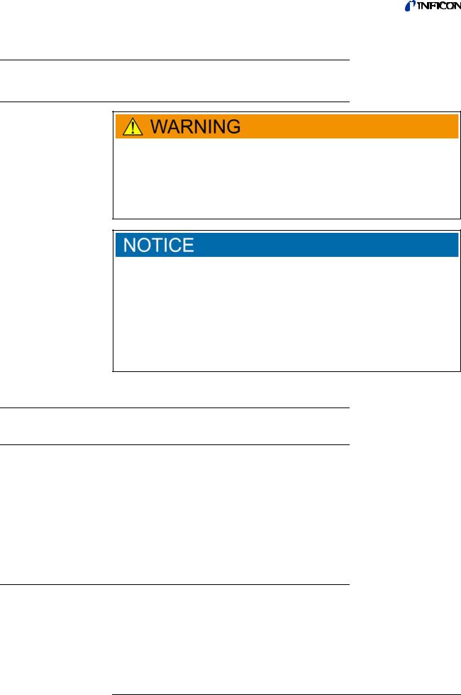
1.3.1Warnings
Imminent threat of danger resulting in death or severe injuries
Dangerous situation potentially resulting in death or severe injuries
Dangerous situation resulting in minor injuries
Dangerous situation resulting in damage to property or the environment
Translation of the original operating instructions HLD6000, kina43e1-a, 1408
1 About these instructions |
7 |

Translation of the original operating instructions HLD6000, kina43e1-a, 1408
81 About these instructions

Translation of the original operating instructions HLD6000, kina43e1-a, 1408
2Safety
2.1Intended use
The device is a leak detector for sniffer leak detection. Use the device to locate and quantify leaks on test objects. The HLD6000 sniffs for different gases depending on which sniffer line is connected. The following sniffer lines are available:
SMART sniffer line for R22, R32, R134a, R404A, R407C, R410A, R1234yf and 3 additional gases from the selectable gases that are verifiable by the device.
Sniffer line for R744 (CO2)
Sniffer line for R600a and R290.
A test object always contains gas under overpressure. Check the exterior of the test objects for escaping gas using a sniffer line (sniffing method).
►You must install, operate and service the device only in compliance with these operating instructions.
►Adhere to the restrictions of use (see "4.4 Technical data", page 17).
Unauthorized use |
► Do not suck up liquids with the device. |
►Never hold the sniffer probe into liquids but sniff only for gases.
2.2Owner requirements
Safety conscious operation
Personnel qualifications
►Operate the device only when it is in technically perfect working order.
►Operate the device only as specified in a safety-conscious and hazard-conscious manner and in compliance with these operating instructions.
►Comply with the following regulations and monitor their compliance:
–Intended use
–Generally applicable safety and accident prevention regulations
–International, national and local standards and guidelines
–Additional provisions and regulations that are specific to the unit
►Use only original parts or parts approved by the manufacturer.
►Keep these operating instructions available at the equipment location.
►Allow only qualified service technicians to work with and on the device. The qualified service technicians must have received training on the device.
►Allow personnel in training to work with and on the device only under the supervision of trained qualified service technicians.
►Make sure that the authorized personnel have read and understood the operating instructions and all other applicable documents, especially the information on safety, maintenance and repairs, before starting work (see "1.2 Other applicable documents", page 7).
►Define the responsibilities, authorizations and supervision of personnel.
2 Safety |
9 |

2.3Operator requirements
►Read, observe and follow the information in these operating instructions and the working instructions created by the owner, especially the safety instructions and warnings.
►Carry out any work only based on the complete operating instructions.
►If you have any questions regarding operation or maintenance that you cannot find answers to in these instructions, please contact INFICON customer service.
2.4Dangers
Dangers from electric power
Dangers from liquids and chemical substances
Dangers from strong exposure to light
The device was built according to the state of the art and the recognized safety regulations. Nevertheless, improper use can result in danger to life and limb of the operator or other persons and damage to the device and other property.
Considerable voltages arise inside the device. Touching parts where electrical voltage is applied can result in death.
►Disconnect the device from the power supply prior to any installation and maintenance work. Make sure that the electric power supply cannot be reconnected without authorization.
Contact of the sniffer tip with live parts may result in danger to life.
►Before starting the leak test, disconnect electrically operated test objects from the power supply. Make sure that the electric power supply cannot be reconnected without authorization.
The device contains electric components that can be damaged from high electric voltage.
►Before connecting the device to the power supply, make sure that the supply voltage specified on the device is the same as the local power supply.
Liquids and chemical substances can damage the device.
►Adhere to the restrictions of use (see "4.4 Technical data", page 17).
►Do not suck up liquids with the device.
►Never try to find toxic, caustic, microbiological, explosive, radioactive or other harmful substances with the device.
►Only clean the device using mild household detergents.
►Only use the device outside potentially explosive areas.
►No smoking. Do not subject the device to open fire and avoid sparking.
Eye exposure to LED light can lead to permanent eye damage.
►Do not look into the LEDs of the sniffer handle from a short distance or for longer periods of time.
Translation of the original operating instructions HLD6000, kina43e1-a, 1408
10 |
2 Safety |
Translation of the original operating instructions HLD6000, kina43e1-a, 1408
3Shipment, Transport, Storage
Shipment |
Table 1: Shipment |
|
|
|
|
|
Item |
Quantity |
|
|
|
|
HLD6000 (Basic unit) |
1 |
|
|
|
|
Sniffer line with sniffer tip (100 mm) |
1 |
|
|
|
|
Power supply cable (EU and US version) |
2 |
|
|
|
|
Fuses |
4 |
|
|
|
|
Filter holder for sniffer tip |
5 |
|
|
|
|
Filter blocks for sniffer tip |
4 |
|
|
|
|
Operating instructions |
1 |
|
|
|
|
Interface description |
1 |
|
|
|
|
USB stick with instructions, software |
1 |
|
|
|
► Check the shipment of the product for completeness after receipt. You can also order separately:
the COOL-Check calibration leak.
Accessory list: see "10.1 Accessories and spare parts", page 67
Transport
Damage from transport
Transport in unsuitable packaging material can damage the device.
►Store the original packaging.
►Only transport the device in the original packaging.
Storage |
Always store the device in compliance with the technical data, see "4.4 Technical data", |
|
page 17. |
Losses due to overly prolonged storage
The service life of a COOL-Check is limited.
►Do not create inventories.
►Store the COOL-Check in a cool, dry place.
3 Shipment, Transport, Storage |
11 |

Translation of the original operating instructions HLD6000, kina43e1-a, 1408
12 |
3 Shipment, Transport, Storage |

4Description
4.1Function
The HLD6000 comprises of a basic unit and a sniffer line.
The HLD6000 can, depending on the model, verify and quantify gases sucked in by the sniffer line with the help of an infrared gas analyzer.
The key assemblies of the HLD6000 are:
Sniffer probe with sensor assembly,
Basic unit with pump system, electric and electronic assemblies.
A source emits infrared light in an optical cell through which the sucked-in gas flows. This light is filtered such that only light with a certain wavelength drops onto an infrared sensor.
If there is a leak and gas gets into the chamber with the sucked-in air then part of the infrared radiation is absorbed by the gas.
This means that the intensity of the light which meets the sensor is reduced.
The change in light intensity is electronically amplified, digitalized and then optically and acoustically displayed by the microprocessor after evaluation.
The underground concentration of the sample gas or other interfering gases are taken into consideration and balanced out due to a reference measurement of the ambient air.
Translation of the original operating instructions HLD6000, kina43e1-a, 1408
4 Description |
13 |
4.2Basic unit
The basic unit is only called a “device” in the following as long as the meaning remains clear.
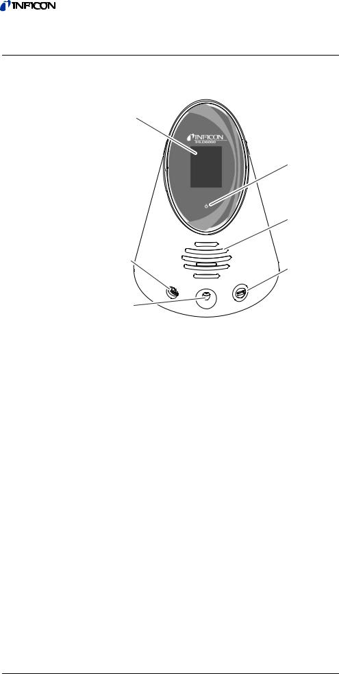
Fig. 1: Frontal view |
|
a Touch screen |
d USB port |
b LED power indicator |
e Calibration opening for internal calibration |
c Speaker |
f Sniffer line connection port |
b LED power indicator |
|
Operating display with 3 statuses: |
|
–green = in operation
–flashing green = unit in operation, display switched off
–red = malfunction
d USB port
For use of a USB stick see "5.6 Using a USB stick", page 27.
Translation of the original operating instructions HLD6000, kina43e1-a, 1408
14 4 Description
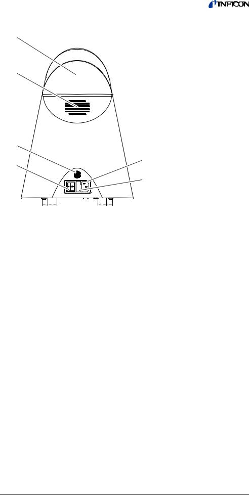
Fig. 2: Rear view |
|
a Mains plug |
d Carry handle |
b M12 socket |
e Power cable connection |
c Ventilation slots |
f Cover for fuse holder |
a Mains plug
The mains plug is used to switch the device on and off.
bM12 socket, 8-pin
–For connection of the INFICON I/O module, available as an accessory see "6.3.8 I/O module", page 36.
–Length of the data cable: Max. 30 m
f Cover for fuse holder
For exchanging fuses see "8.1.3 Replacing the fuses", page 62.
Translation of the original operating instructions HLD6000, kina43e1-a, 1408
4 Description |
15 |

Fig. 3: View from below |
|
a Rating plate with information regarding |
c COOL-Check calibration leak behind the cover |
supply voltage, serial number and |
|
productio date. |
|
b Filter plates |
|
4.3Sniffer line
|
You need a sniffer line to operate the device. There are sniffer lines for verification of a sin- |
|
gle gas or sniffer lines for the verification of several gases see "2.1 Intended use", page 9 |
|
and see "10.1 Accessories and spare parts", page 67. The sniffer line which is delivered as |
|
standard is 4.8 m long. |
|
The sniffer line is made of a black line, a sniffer probe, and a sniffer tip. The filter holder at |
|
the end of the sniffer tip is made of plastic. This reduces the risk of scratching the surfaces |
|
to be sniffed. |
Sniffer tip |
There are rigid and flexible sniffer tips of different lengths, see "10.1 Accessories and spare |
|
parts", page 67. |
Sniffer probe |
During measurement it is possible to switch the setpoint using the button on the sniffer |
|
probe, provided that this function is activated, see "6.4.2 Setting up the sniffer probe", |
|
page 41. |
|
The button on the sniffer probe is also used during calibration, see "6.4.6.2 Calibration |
|
with an internal COOL-Check", page 44. |
16 4 Description
Translation of the original operating instructions HLD6000, kina43e1-a, 1408

Translation of the original operating instructions HLD6000, kina43e1-a, 1408
Fig. 4: Handle: Display and functions |
|
a Key |
d Illumination LED |
b Status LED |
e Sniffer tip |
c Name of gas or sniffer line |
|
If the setpoint is exceeded, the display switches from green to yellow, see Table 7 on
Page 33.
You can also set the illumination LEDs to flash at the lower end of the sniffer probe, see "6.4.2 Setting up the sniffer probe", page 41.
4.4 |
Technical data |
|
|
|
|
|
Table 2: Technical data |
|
|
|
|
|
|
|
|
|
Mechanical Data |
|
|
|
|
|
|
|
|
|
Basic unit |
|
|
|
|
|
|
|
|
|
Dimensions (height; diameter) |
365 mm; 260 mm (14.4 in.; 10.25 in) |
|
|
|
|
|
|
|
|
Weight |
4.1 kg (9 lb.) |
|
|
|
|
|
|
|
|
Length of sniffer line |
4.8 m (15.5 ft.) |
|
|
|
|
|
|
|
|
Weight of sniffer probe |
280 g (0.6 lb.) |
|
|
|
|
|
|
|
|
Ambient conditions |
|
|
|
|
|
|
|
|
|
Permissible ambient temperature (during operation) |
5 °C up to 50 °C (40-122 °F) |
|
|
|
|
|
|
|
|
Permissible storage temperature |
0 °C up to 50 °C (32-122 °F) |
|
|
|
|
|
|
|
|
Max. relative humidity up to 31 °C (87.8 °F) |
80 % |
|
|
|
|
|
|
|
|
Max. relative humidity from 31 °C to 40 °C (87.8 °F-104 °F) |
linearly decreasing from 80% to 50% |
|
|
|
|
|
|
|
|
Max. relative humidity over 40 °C (104 °F) |
50 % |
|
|
|
|
|
|
|
|
Pollution degree |
II |
|
|
|
|
(According to IEC 61010/ Part 1: “Usually, only non-con- |
|
|
|
|
ducting pollution may occur. However, temporary conduc- |
|
|
|
|
tivity caused by condensation is permissible at times.“) |
|
|
|
|
|
|
|
|
Max. altitude above sea level |
2000 m |
|
|
|
|
|
|
4 Description |
17 |

Table 2: Technical data (Contin.)
Electrical data |
|
|
|
Supply voltages and frequencies |
100 … 240V 50/60 Hz |
|
|
Power consumption |
55 VA |
|
|
Protection class |
IP 30 |
|
|
Overvoltage category |
II |
|
|
Mains fuse |
2 x 1 A slow-blowing (Ø 5 × 20 mm) |
|
|
Power supply cable |
2.5 m (8.2 ft.) |
|
|
Length of the data cable on the M12 plug |
Max. 30 m (98.4 ft.) |
|
|
Noise level without signal tones |
< 54 dBA |
|
|
Physical Data |
|
|
|
Minimum detectable leak rate |
|
|
|
R744 (CO2) |
1.0 g/a (0.04 oz/yr) |
R600a/R290 |
1.0 g/a (0.04 oz/yr); for R600a/R290 see "6.4.5 Verifying |
|
R290 with the sniffer line for R600a/R290", page 43 |
|
|
SMART |
0.5 g/a (0.02 oz/yr); see "6.4.4 Setting up the gas for the |
|
SMART sniffer line", page 42 |
|
|
Measurement range of sniffer probes |
|
|
|
Individual gases |
0 - 100 g/a (3.57 oz/yr) |
|
|
SMART |
0 - 300 g/a (10.7 oz/yr) |
|
|
Time constant of the signal from the leakage rates |
< 1 s |
|
|
Gas flow |
|
Measured at 1 atm (1013 mbar) at sea level. The flow rate |
320 sccm |
changes with the geographical height and barometric pres- |
|
sure. |
|
|
|
Time until ready for operation |
< 30 s |
|
|
Response time |
< 1 s |
|
|
Table 3: General factory settings
(For current device settings see "6.7.1 Parameter list", page 50)
Analog output upper limit |
100 g/a |
|
|
Display off after |
1 h |
|
|
Display brightness |
100 % |
|
|
Display maximum value (log.) exponent |
+3 |
|
|
Display maximum value (lin.) |
20.0 g/a |
|
|
Display upper limit (lin.) |
300.0 g/a |
|
|
Display upper limit (log.) exponent. |
+3 |
|
|
Display unit leakage rate |
g/a |
|
|
Auto scale |
on |
|
|
Screen tap sound |
Soft |
|
|
Bus module address |
126 |
|
|
Data record |
Off |
|
|
Diagram of the leakage rate |
Line graph |
|
|
User Gas Factor 1 |
0.0 |
|
|
User Gas Factor 2 |
0.0 |
|
|
User Gas Factor 3 |
0.0 |
|
|
Translation of the original operating instructions HLD6000, kina43e1-a, 1408
18 4 Description

Translation of the original operating instructions HLD6000, kina43e1-a, 1408
Table 3: General factory settings (Contin.)
Error information operator |
No. and text |
|
|
Error information supervisor |
No., text and info |
|
|
Filter change request |
On |
|
|
Gas in the SMART sniffer line |
R134a |
|
|
I/O module protocol |
ASCII |
|
|
Interval for auto standby |
2 min. |
|
|
Interval for calibration request |
60 min. |
|
|
Calibration factor |
15.0 (Calibration factor during initial setup. The calibration |
|
factor cannot be reset to factory settings. It can be changed |
|
by the service team.) |
|
|
Config. Analog output 1 |
Leakage rate linear |
|
|
Config. Analog output 2 |
Leakage rate linear |
|
|
Configuration PLC Output 1 |
Setpoint 1 (inverse) |
|
|
Configuration PLC Output 2 |
Setpoint 2 (inverse) |
|
|
Configuration PLC Output 3 |
Open |
|
|
Configuration PLC Output 4 |
Open |
|
|
Configuration PLC Output 5 |
Measuring |
|
|
Configuration PLC Output 6 |
Error (inverse) |
|
|
Configuration PLC Output 7 |
CAL request (inverse) |
|
|
Configuration PLC Output 8 |
Open (inverse) |
|
|
Configuration PLC Input 1 |
No function |
|
|
Configuration PLC Input 2 |
No function |
|
|
Configuration PLC Input 3 |
Start/Stop (inverse) |
|
|
Configuration PLC Input 4 |
No function |
|
|
Configuration PLC Input 5 |
CAL external |
|
|
Configuration PLC Input 6 |
No function |
|
|
Configuration PLC Input 7 |
Delete |
|
|
Configuration PLC Input 8 |
No function |
|
|
Configuration PLC Input 9 |
No function |
|
|
Configuration PLC Input 10 |
No function |
|
|
Volume |
5 |
|
|
LR setpoint 1 |
5.0 g/a |
|
|
LR setpoint 2 |
10.0 g/a |
|
|
Display measured value |
On |
|
|
Module on the M12 socket |
I/O |
|
|
Phase |
20 (Phase during initial setup. The phase cannot be reset to |
|
factory settings. It can be changed by the service team.) |
|
|
Calibration leak external |
10 g/a |
|
|
Interface unit leakage rate |
g/a |
|
|
Sniffer light alarm config. |
Flashing |
|
|
Sniffer light brightness |
4 |
|
|
Probe key configuration |
Setpoint |
|
|
Setpoint audio alarm |
Setpoint |
|
|
Record interval |
500 ms |
|
|
Memory location |
USB |
|
|
4 Description |
19 |

Table 3: General factory settings (Contin.)
Language |
English |
|
|
Value axis decades |
3 |
|
|
Value axis grid |
Linear |
|
|
Time axis scale |
30 s |
|
|
Table 4: Factory settings for access authorization |
|
|
|
Parameter Access Ctrl. |
|
|
|
Analog output upper limit |
Supervisor |
|
|
Display off after |
Operator |
|
|
Display brightness |
Operator |
|
|
Display maximum value (log.) exponent |
Operator |
|
|
Display maximum value (lin.) |
Operator |
|
|
Display upper limit (lin.) |
Operator |
|
|
Display upper limit (log.) exponent |
Operator |
|
|
Display unit leakage rate |
Operator |
|
|
Auto scale |
Operator |
|
|
Screen tap sound |
Operator |
|
|
Bus module address |
Supervisor |
|
|
Data record |
Operator |
|
|
Date |
Supervisor |
|
|
Diagram of the leakage rate |
Operator |
|
|
User Gas Factor |
Supervisor |
|
|
Error information operator |
Supervisor |
|
|
Error information supervisor |
Supervisor |
|
|
Filter change request |
Supervisor |
|
|
Gas in the SMART sniffer line |
Supervisor |
|
|
I/O module protocol |
Supervisor |
|
|
Interval for auto standby |
Supervisor |
|
|
Interval for calibration request. |
Supervisor |
|
|
Calibration factor |
Service |
|
|
Config. Analog output |
Supervisor |
|
|
Configuration PLC Output |
Supervisor |
|
|
Configuration PLC Input |
Supervisor |
|
|
Volume |
Operator |
|
|
LR setpoint |
Supervisor |
|
|
Display measured value |
Operator |
|
|
Module on the M12 socket |
Supervisor |
|
|
Phase |
Service |
|
|
Calibration leak external |
Supervisor |
|
|
Interface unit leakage rate |
Supervisor |
|
|
Sniffer light alarm config. |
Supervisor |
|
|
Sniffer light brightness |
Supervisor |
|
|
Probe key configuration |
Supervisor |
|
|
Setpoint audio alarm |
Supervisor |
|
|
Record interval |
Operator |
|
|
Translation of the original operating instructions HLD6000, kina43e1-a, 1408
20 4 Description
Table 4: Factory settings for access authorization (Contin.)
Memory location |
Operator |
|
|
Language |
Operator |
|
|
Time |
Supervisor |
|
|
Value axis decades |
Operator |
|
|
Value axis grid |
Operator |
|
|
Time axis scale |
Operator |
|
|
Translation of the original operating instructions HLD6000, kina43e1-a, 1408
4 Description |
21 |

Description 4 22
Translation of the original operating instructions HLD6000, kina43e1-a, 1408
Translation of the original operating instructions HLD6000, kina43e1-a, 1408
5Installation
5.1Setup
Danger from moisture and electricity
Moisture penetrating the device can lead to personal injury from electric shocks and to material damage from short circuits.
►Only operate the device in a dry environment.
►Operate the device away from sources of liquid and moisture.
Material damage from overheated device
The device heats up during operation and can overheat without sufficient ventilation.
►Please note the technical data, see page 17.
►Ensure sufficient ventilation, especially on the ventilation slots: at least 20 cm of free space on the sides, at least 10 cm in the front and rear.
►Keep heat sources away from the device.
►Do not expose the device to direct sunlight.
5.2Sniffer line
5.2.1Connecting the sniffer line
Connect the sniffer line before you start up the device.
If the sniffer line is not connected then the device reports an error.
If you remove the sniffer line during operation, the device also reports an error.
1Align the red marking on the sniffer line plug with the red marking on the socket of the device (see Fig. 1 on Page 14).
2Push the sniffer line plug into the socket on the device until it locks into place. The plug may no longer be easy to move.
5.2.2Exchanging the sniffer line
1 Select the sniffer line of the gas you wish to detect.
2 Switch the device off.
3To release the plug on the sniffer line from the socket of the device, pull the grooved ring on the plug until the lock is opened.
4 Pull off the sniffer line.
5 Installation |
23 |
 Loading...