


IWME126

1
GB
English,1
Contents
Installation, 2-3-4-5-6-7
Unpacking and levelling
Electric and water connections
The first wash cycle
Technical details
Instructions for the fitter
Washing machine description, 8-9
Control panel
Leds
Starting and Programmes, 10
Briefly: how to start a programme
Programme table
Personalisations, 11
Setting the temperature
Setting the spin speed
Functions
Detergents and laundry, 12
Detergent dispenser
Bleach cycle
Preparing your laundry
Special items
Precautions and advice, 13
General safety
Disposal
Saving energy and respecting the environment
Care and maintenance, 14
Cutting off the water or electricity supply
Cleaning your appliance
Cleaning the detergent dispenser
Caring for your appliance door and drum
Cleaning the pump
Checking the water inlet hose
Troubleshooting, 15
Service and Guarantee, 16-17-18
Before calling for Assistance
WASHING MACHINE
IWME 126
Instructions for use
GB
2
GB
Installation
!Keep this instruction manual in a safe place for
future reference. Should the appliance be sold,
transferred or moved, make sure the instruction
manual accompanies the washing machine to inform
the new owner as to its operation and features.
!Read these instructions carefully: they contain vital
information on installation, use and safety.
Unpacking and levelling
Unpacking
1. Unpack the washing machine.
2. Check whether the washing machine has been
damaged during transport. If this is the case, do not
install it and contact your retailer.
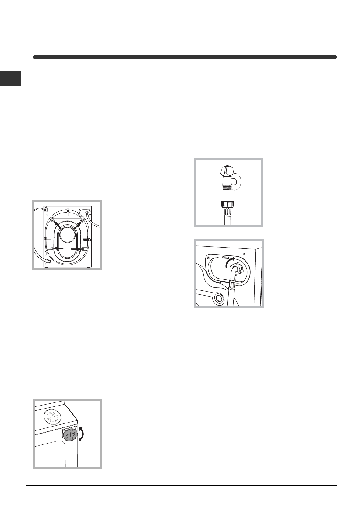
3. Remove the 4
protective screws and
the rubber bush with the
respective spacer,
situated on the rear of
the appliance (see also
the installation leaflet).
NB:The plastic spacers
may fall down inside the
machine once the bolt
has been removed, and will not interfere with the
operation of the machine.
4. Seal the gaps using the plastic plugs provided.
5. Keep all the parts: you will need them again if the
washing machine needs to be moved to another
location.
!Packaging materials are not children's toys.
Levelling
Your machine may make a considerable amount of noise
if the two front feet have not been adjusted correctly.
1. Install the washing machine on a flat sturdy floor,
without resting it up against walls, furniture cabinets
or other.
2. If the floor is not
perfectly level, compen-
sate for any unevenness
by tightening or
loosening the adjustable
front feet (see figure);
the angle of inclination,
measured according to
the worktop, must not
exceed 2°.
Levelling your appliance correctly will provide it with
stability and avoid any vibrations, noise and shifting
during operation. If it is placed on a fitted or loose
carpet, adjust the feet in such a way as to allow
enough room for ventilation beneath the washing
machine.
Electric and water connections
Connecting the water inlet hose
1. Connect the supply
pipe by screwing it to a
cold water tab using a
¾ gas threaded
connection (see figure).
Before performing the
connection, allow the
water to run freely until
it is perfectly clear.
2. Connect the other end
of the water inlet hose to
the washing machine,
screwing it onto the
appliance's cold water
inlet, situated on the top
right-hand side on the
rear of the appliance (see
figure).
3. Make sure there are no kinks or bends in the
hose.
! The water pressure at the tap must be within the
values indicated in the Technical details table
(on the next page).
! If the water inlet hose is not long enough, contact
a specialist store or an authorised serviceman.
! Ensure that the supply taps are allowing water
through. Old taps may seize in the closed position
and thus prevent water reaching the machine.
3
GB
• the supply voltage is included within the values i
ndicated on the Technical details table
(see page 5);
• the socket is compatible with the washing
machine's plug. If this is not the case, replace
the socket or the plug.
Your appliance is now supplied with a 13 amp fused
plug it can be plugged into a 13 amp socket for
immediate use. Before using the appliance please
read the instructions below.
WARNING - THIS APPLIANCE MUST BE EARTHED.
THE FOLLOWING OPERATIONS SHOULD BE
CARRIED OUT BY A QUALIFIED ELECTRICIAN.
Replacing the fuse:
When replacing a faulty fuse, a 13 amp ASTA
approved fuse to BS 1362 should always be used,
and the fuse cover re-fitted. If the fuse cover is lost,
the plug must not be used until a replacement is
obtained.
Replacement fuse covers:
If a replacement fuse cover is fitted, it must be of
the correct colour as indicated by the coloured
marking or the colour that is embossed in words on
the base of the plug. Replacements can be obtained
directly from your nearest Service Depot.
Removing the plug:
If your appliance has a non-rewireable moulded plug
and you should wish to re-route the mains cable
through partitions, units etc., please ensure that
either:
the plug is replaced by a fused 13 ampere re-
wearable plug bearing the BSI mark of approval.
or:
the mains cable is wired directly into a 13 amp cable
outlet, controlled by a switch, (in compliance with
BS 5733) which is accessible without moving the
appliance.
Disposing of the plug:
Ensure that before disposing of the plug itself, you
make the pins unusable so that it cannot be
accidentally inserted into a socket.
Instructions for connecting cable to an alternative plug:
Important: the wires in the mains lead are coloured
in accordance with the following code:
Green & Yellow Earth
Blue Neutral
Brown Live
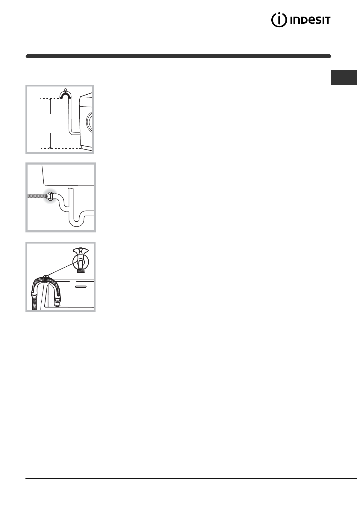
Connecting the drain hose
Connect the drain hose,
without bending it, to a
draining duct or a wall
drain situated between
65 and 100 cm from
the floor;
The drain hose may be
connected to an
under-sink trap. Before
connecting the drain
hose from the machine
ensure that any blanks
or removable ends
have been taken off
the spigot.
If it is place over the
edge of a basin or sink
be sure the free end of
the hose should not be
underwater.
! We advise against the use of hose extensions; in
case of absolute need, the extension must have the
same diameter as the original hose and must not
exceed 150 cm in length.
Ensure that if the drain hose is pushed into a
standpipe, that the end does not go down more
than 15cms (6 inches). If the hose is pushed down
too far, this may cause the machine to self -syphon
ie. continuously empty as it is filling.
Electric connection
Before plugging the appliance into the mains
socket, make sure that:
• the socket is earthed and in compliance with the
applicable law;
• the socket is able to sustain the appliance's
maximum power load indicated in the Technical
details table (see page 5);
65 - 100 cm
Where it connects to
the waste water pipe
cut end off spigot or
remove the blanking cap
4
GB
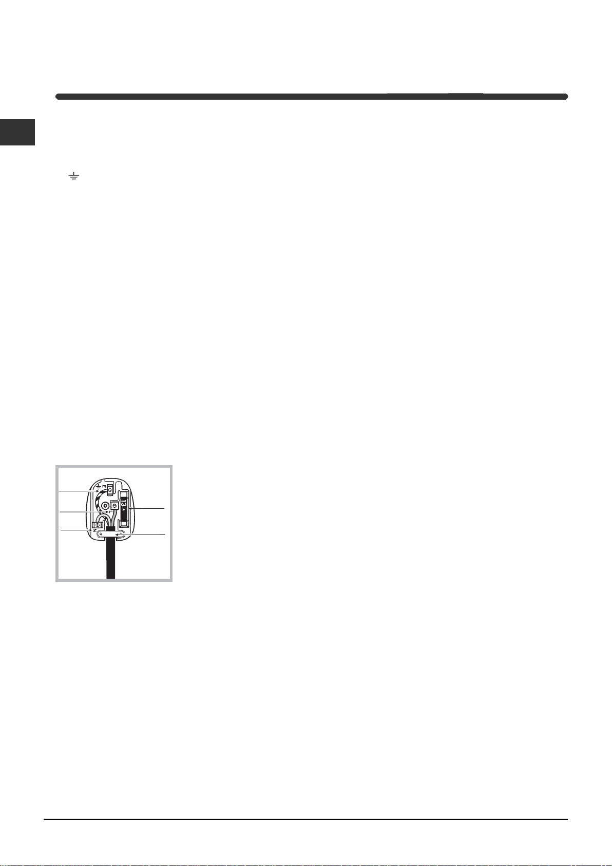
As the colours of the wires in the lead may not
correspond with the coloured markings identifyng
the terminals in your plug, proceed as follows:
Connect Green & Yellow wire to terminal marked E
or
or coloured Green or Green & Yellow.
Connect Brown wire to terminal marked L or
coloured Red.
Connect Blue wire to terminal marked N or coloured
Black.
If a 13 amp plug (BS 1363) is used it must be fitted
with a
13 amp fuse, either in the plug or adaptor or at the
distribution board.
If you are in any doubt the electrical supply to your
machine, consult a qualified electrician before use.
How to connect an alternative plug:
The wires in this mains lead are coloured in
accordance with the following code:
BLUE NEUTRAL (N)
BROWN LIVE (L)
GREEN & YELLOW EARTH (E)
Disposing of the appliance:
When disposing of the appliance please remove the
plug by cutting the mains cable as close as possible
to the plug body and dispose of it as described
above.
! The washing machine should not be installed in an
outdoor environment, not even when the area is
sheltered, because it may be very dangerous to
leave it exposed to rain and thunderstorms.
! When the washing machine is installed, the mains
socket must be within easy reach.
! Do not use extensions or multiple sockets.
! The power supply cable must never be bent or
dangerously compressed.
! The power supply cable must only be replaced by
an authorised serviceman.
Warning! The company denies all liability if and when
these norms are not respected.
The first wash cycle
Once the appliance has been installed, and before
you use it for the first time, run a wash cycle with
detergent and no laundry, setting the 90°C
programme without a pre-wash cycle.
GREEN &
YELLOW
BROWN
BLUE
13 ampere fuse
CROSS-BAR
CORD GRIP
5
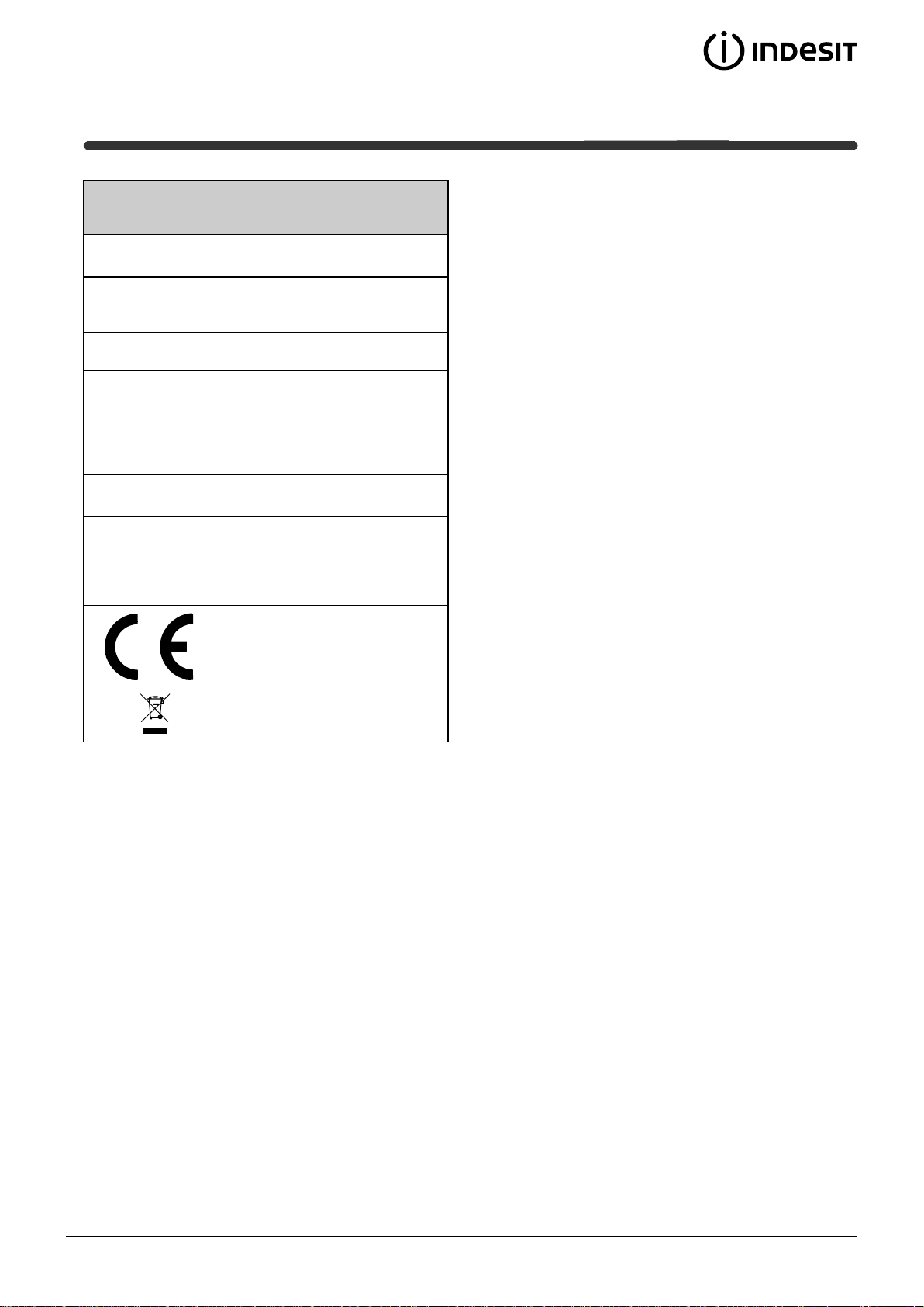
Technical details
Model
IW ME 1 26
Dimensions
59.5 cm wide
81,5 cm high
54,5 cm deep
Capacity
from 1 to 6 kg
Electric
connections
please refer to th e t ech ni cal dat a plat e
fixed t o t he mach i ne
Water
connections
maximu m press u re 1 MPa (10 bar)
minimu m pres s ur e 0.05 MPa (0 .5 bar)
drum capaci ty 5 2 li tr es
Spin sp ee d
up to 1200 rpm
Control
programmes
according to
EN 60456
directive
programme 2; temperature 60°C;
run wi th a l oad o f 6 k g.
This appliance is compliant wit h th e
following European Communit y
Direct i ves:
- 89/336/CEE of 03/05/89
(Electromagnetic Compatibility) and
subsequent amendments
- 2002/96/CE
- 2006/95/CE (Low Voltage)
6
GB
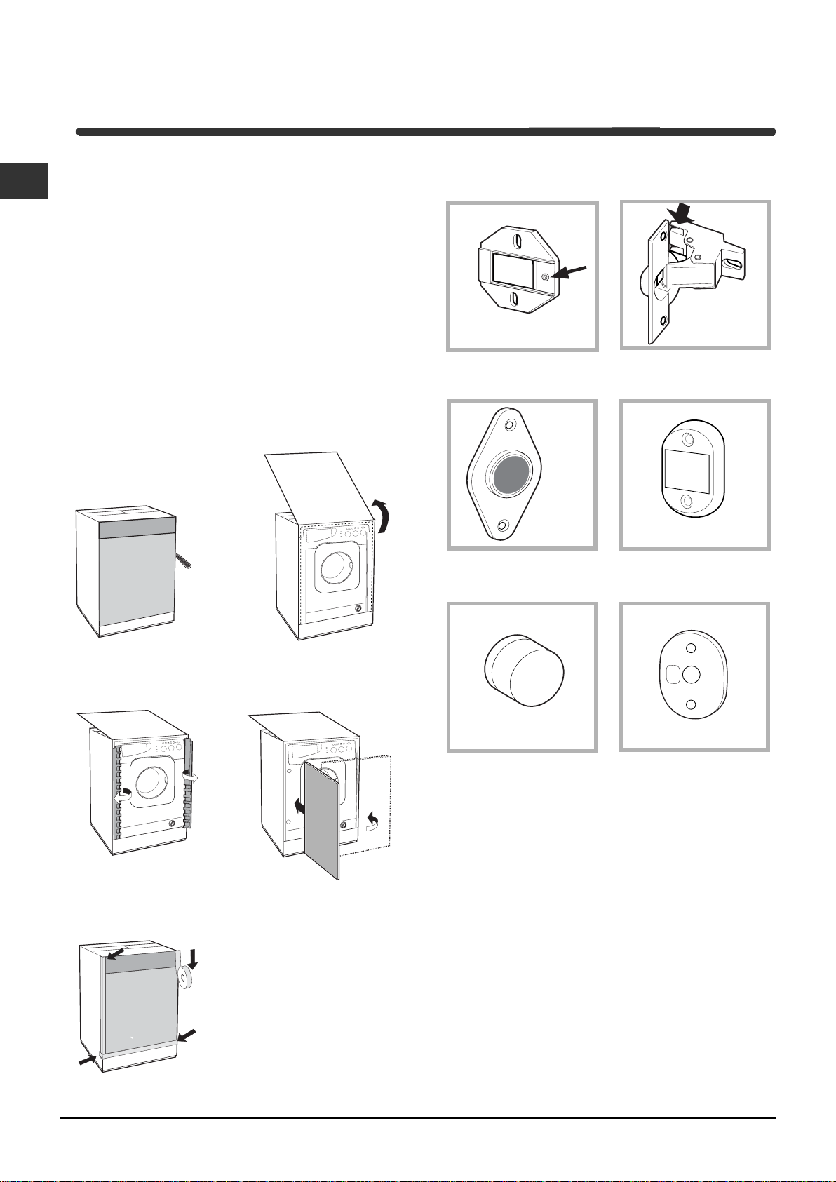
Instructions for the fitter
Mounting the wooden panel onto the door and
inserting the machine into cabinets:
In the case where the machine must be shipped for final
installation after the wooden panel has been mounted, we
suggest leaving it in its original packaging. The packaging
was designed to make it possible to mount the wooden
panel onto the machine without removing it completely
(see figures below).
The wooden panel that covers the face of the machine
must not be less than 18 mm in thickness and can be
hinged on either the right or left. For the sake of
practicality when using the machine, we recommend that
the panel be hinged on the same side as the door for the
machine itself - the left.
A
B
C
D
E
Door Mounting Accessories (Fig. 1-2-3-4-5).
Fig. 1
N° 2 Hinges
N° 1 Magnet N° 1 Magnet plate
N° 1 Rubber plug
N° 2 Hinge Supports
N° 4 Spacers
Fig. 2
Fig. 3 Fig. 4
Fig. 5
Fig. 4/B
- No. 6 type A self-threading screws, l =13 mm.
- No. 2 type B metric, countersunk screws, l =25; for
fastening the magnet plate to the cabinet.
- No. 4 type C metric screws, l =15 mm; for mounting the
hinge supports to the cabinet.
- No. 4 type D metric screws, l =7 mm; for mounting the
hinges on the supports.
Mounting the Parts onto the Face of the Machine.
- Fit the hinge supports to the appliance front panel,
positioning the hole marked with an arrow in fig. 1 so that it
is on the inner side of the front panel. Fit a spacer (fig. 4/B)
between the surfaces using type C screws.
- Fit the magnet plate at the top of the opposite side,
using type B screws to fix two spacers (fig. 4/B) between
the plate and the surface.
Tur seite
 Loading...