


 Loading...
945GSE2 3.5" Motherboard
IEI Technology Corp.
MODEL:
WAFER-945GSE2
3.5" SBC with 1.6 HGz Intel® Atom™ N270, VGA/LVDS, Dual PCIe GbE, CF Type II, USB, SATA,
On-board 1 GB Memory and PC/104
User Manual
Rev. 2.00 – 28 October, 2011

WAFER-945GSE2 3.5" Motherboard
|
|
|
|
Revision |
|
|
|
|
|
|
|
|
|
|
|
Date |
Version |
Changes |
|
|
|
|
|
|
|
28 October, 2011 |
2.00 |
Updated for R20 version |
|
|
|
|
|
|
|
20 |
September, 2011 |
1.03 |
Updated section 1.5 Data Flow |
|
|
|
|
|
|
25 |
June, 2009 |
1.02 |
New photographs added |
|
|
|
|
|
|
11 |
March, 2009 |
1.01 |
Model name update |
|
|
|
|
|
|
17 |
February, 2009 |
1.00 |
Initial release |
|
|
|
|
|
Page ii

WAFER-945GSE2 3.5" Motherboard
Copyright
COPYRIGHT NOTICE
The information in this document is subject to change without prior notice in order to improve reliability, design and function and does not represent a commitment on the part of the manufacturer.
In no event will the manufacturer be liable for direct, indirect, special, incidental, or consequential damages arising out of the use or inability to use the product or documentation, even if advised of the possibility of such damages.
This document contains proprietary information protected by copyright. All rights are reserved. No part of this manual may be reproduced by any mechanical, electronic, or other means in any form without prior written permission of the manufacturer.
TRADEMARKS
All registered trademarks and product names mentioned herein are used for identification purposes only and may be trademarks and/or registered trademarks of their respective owners.
Page iii
WAFER-945GSE2 3.5" Motherboard
Table of Contents |
|
1 INTRODUCTION.......................................................................................................... |
1 |
1.1 INTRODUCTION........................................................................................................... |
2 |
1.2 MODEL VARIATIONS ................................................................................................... |
2 |
1.3 CONNECTORS ............................................................................................................. |
3 |
1.4 DIMENSIONS............................................................................................................... |
5 |
1.4.1 Board Dimensions.............................................................................................. |
5 |
1.4.2 External Interface Panel Dimensions ................................................................ |
6 |
1.5 DATA FLOW ................................................................................................................ |
7 |
1.6 TECHNICAL SPECIFICATIONS ...................................................................................... |
8 |
2 PACKING LIST........................................................................................................... |
10 |
2.1 ANTI-STATIC PRECAUTIONS ....................................................................................... |
11 |
2.2 UNPACKING PRECAUTIONS........................................................................................ |
11 |
2.3 PACKING LIST........................................................................................................... |
12 |
2.4 OPTIONAL ITEMS...................................................................................................... |
13 |
3 CONNECTORS ........................................................................................................... |
14 |
3.1 PERIPHERAL INTERFACE CONNECTORS..................................................................... |
15 |
3.1.1 WAFER-945GSE2 Layout ................................................................................ |
15 |
3.1.2 Peripheral Interface Connectors ..................................................................... |
16 |
3.1.3 External Interface Panel Connectors............................................................... |
17 |
3.2 INTERNAL PERIPHERAL CONNECTORS ...................................................................... |
17 |
3.2.1 ATX Power Connector ..................................................................................... |
17 |
3.2.2 ATX Power Supply Enable Connector ............................................................. |
18 |
3.2.3 Audio Connector (10-pin) ................................................................................ |
19 |
3.2.4 Backlight Inverter Connector .......................................................................... |
20 |
3.2.5 Battery Connector............................................................................................ |
21 |
3.2.6 CompactFlash® Socket.................................................................................... |
22 |
3.2.7 Digital Input/Output (DIO) Connector............................................................ |
23 |
3.2.8 Fan Connector (+12V, 3-pin) .......................................................................... |
24 |
3.2.9 Keyboard/Mouse Connector ............................................................................ |
25 |
Page iv

WAFER-945GSE2 3.5" Motherboard |
|
3.2.10 LED Connector .............................................................................................. |
26 |
3.2.11 LVDS LCD Connector.................................................................................... |
27 |
3.2.12 PC/104 Connector ......................................................................................... |
28 |
3.2.13 PC/104 Power Input Connector..................................................................... |
29 |
3.2.14 Power Button Connector................................................................................ |
30 |
3.2.15 Reset Button Connector ................................................................................. |
31 |
3.2.16 SATA Drive Connectors ................................................................................. |
31 |
3.2.17 Serial Port Connector, RS-232/422/485 ........................................................ |
32 |
3.2.18 SPI Flash Connector...................................................................................... |
33 |
3.2.19 USB Connectors (Internal) ............................................................................ |
34 |
3.3 EXTERNAL PERIPHERAL INTERFACE CONNECTOR PANEL ......................................... |
35 |
3.3.1 Ethernet Connectors ........................................................................................ |
36 |
3.3.2 Serial Port Connectors (COM1)...................................................................... |
37 |
3.3.3 USB Connectors............................................................................................... |
37 |
3.3.4 VGA Connector ................................................................................................ |
38 |
4 INSTALLATION ......................................................................................................... |
39 |
4.1 ANTI-STATIC PRECAUTIONS ...................................................................................... |
40 |
4.2 INSTALLATION CONSIDERATIONS.............................................................................. |
40 |
4.3 CF CARD INSTALLATION .......................................................................................... |
41 |
4.4 JUMPER SETTINGS .................................................................................................... |
43 |
4.4.1 AT/ATX Power Select Jumper .......................................................................... |
43 |
4.4.2 CF Card Setup ................................................................................................. |
44 |
4.4.3 Clear CMOS Jumper........................................................................................ |
45 |
4.4.4 COM 2 Function Select Jumper....................................................................... |
46 |
4.4.5 LVDS Voltage Selection.................................................................................... |
47 |
4.5 CHASSIS INSTALLATION............................................................................................ |
48 |
4.5.1 Airflow.............................................................................................................. |
48 |
4.5.2 Motherboard Installation................................................................................. |
49 |
4.6 INTERNAL PERIPHERAL DEVICE CONNECTIONS........................................................ |
49 |
4.6.1 SATA Drive Connection ................................................................................... |
49 |
4.6.2 Dual RS-232 Cable Connection (w/o bracket) (Optional) .............................. |
51 |
4.6.3 Keyboard/Mouse Y-cable Connector ............................................................... |
52 |
4.6.4 Audio Kit Installation....................................................................................... |
54 |
4.6.5 PC/104 Module Installation............................................................................. |
54 |
Page v

WAFER-945GSE2 3.5" Motherboard |
|
4.6.6 USB Cable (Dual Port without Bracket) (Optional)........................................ |
55 |
4.7 EXTERNAL PERIPHERAL INTERFACE CONNECTION ................................................... |
56 |
4.7.1 LAN Connection............................................................................................... |
57 |
4.7.2 Serial Device Connection ................................................................................ |
57 |
4.7.3 USB Connection (Dual Connector) ................................................................. |
58 |
4.7.4 VGA Monitor Connection ................................................................................ |
59 |
5 BIOS.............................................................................................................................. |
61 |
5.1 INTRODUCTION......................................................................................................... |
62 |
5.1.1 Starting Setup................................................................................................... |
62 |
5.1.2 Using Setup ...................................................................................................... |
62 |
5.1.3 Getting Help..................................................................................................... |
63 |
5.1.4 Unable to Reboot after Configuration Changes .............................................. |
63 |
5.1.5 BIOS Menu Bar................................................................................................ |
63 |
5.2 MAIN........................................................................................................................ |
64 |
5.3 ADVANCED ............................................................................................................... |
65 |
5.3.1 CPU Configuration.......................................................................................... |
66 |
5.3.2 IDE Configuration ........................................................................................... |
67 |
5.3.2.1 IDE Master, IDE Slave ............................................................................. |
68 |
5.3.3 Super IO Configuration ................................................................................... |
73 |
5.3.4 Hardware Health Configuration...................................................................... |
74 |
5.3.5 Power Configuration ....................................................................................... |
78 |
5.3.5.1 ACPI configuration ................................................................................... |
79 |
5.3.5.2 APM Configuration................................................................................... |
80 |
5.3.6 Remote Access Configuration .......................................................................... |
82 |
5.3.7 USB Configuration........................................................................................... |
85 |
5.3.8 iEi Feature ....................................................................................................... |
86 |
5.4 PCI/PNP................................................................................................................... |
87 |
5.5 BOOT........................................................................................................................ |
90 |
5.5.1 Boot Settings Configuration............................................................................. |
90 |
5.5.2 Boot Device Priority ........................................................................................ |
92 |
5.6 SECURITY................................................................................................................. |
93 |
5.7 CHIPSET ................................................................................................................... |
94 |
5.7.1 North Bridge Chipset Configuration ............................................................... |
94 |
5.7.2 South Bridge Chipset Configuration................................................................ |
98 |
Page vi

WAFER-945GSE2 3.5" Motherboard |
|
5.8 EXIT ......................................................................................................................... |
99 |
6 SOFTWARE DRIVERS ............................................................................................ |
101 |
6.1 AVAILABLE SOFTWARE DRIVERS ............................................................................ |
102 |
6.2 STARTING THE DRIVER PROGRAM .......................................................................... |
102 |
6.3 CHIPSET DRIVER INSTALLATION............................................................................. |
104 |
6.4 VGA DRIVER INSTALLATION.................................................................................. |
108 |
6.5 LAN DRIVER INSTALLATION................................................................................... |
113 |
6.6 AUDIO DRIVER INSTALLATION ................................................................................ |
115 |
A BIOS OPTIONS ......................................................................................................... |
118 |
B ONE KEY RECOVERY........................................................................................... |
121 |
B.1 ONE KEY RECOVERY INTRODUCTION .................................................................... |
122 |
B.1.1 System Requirement....................................................................................... |
123 |
B.1.2 Supported Operating System ......................................................................... |
124 |
B.2 SETUP PROCEDURE FOR WINDOWS........................................................................ |
125 |
B.2.1 Hardware and BIOS Setup ............................................................................ |
125 |
B.2.2 Create Partitions ........................................................................................... |
126 |
B.2.3 Install Operating System, Drivers and Applications..................................... |
129 |
B.2.4 Build-up Recovery Partition.......................................................................... |
130 |
B.2.5 Create Factory Default Image....................................................................... |
132 |
B.3 SETUP PROCEDURE FOR LINUX .............................................................................. |
137 |
B.4 RECOVERY TOOL FUNCTIONS ................................................................................ |
140 |
B.4.1 Factory Restore ............................................................................................. |
142 |
B.4.2 Backup System ............................................................................................... |
143 |
B.4.3 Restore Your Last Backup.............................................................................. |
144 |
B.4.4 Manual........................................................................................................... |
145 |
B.5 OTHER INFORMATION ............................................................................................ |
146 |
B.5.1 Using AHCI Mode or ALi M5283 / VIA VT6421A Controller....................... |
146 |
B.5.2 System Memory Requirement ........................................................................ |
148 |
C TERMINOLOGY ..................................................................................................... |
149 |
D DIGITAL I/O INTERFACE..................................................................................... |
153 |
D.1 INTRODUCTION...................................................................................................... |
154 |
D.2 DIO CONNECTOR PINOUTS ................................................................................... |
154 |
Page vii

WAFER-945GSE2 3.5" Motherboard |
|
D.3 ASSEMBLY LANGUAGE SAMPLES........................................................................... |
154 |
D.3.1 Enable the DIO Input Function .................................................................... |
154 |
D.3.2 Enable the DIO Output Function.................................................................. |
155 |
E WATCHDOG TIMER............................................................................................... |
156 |
F HAZARDOUS MATERIALS DISCLOSURE........................................................ |
159 |
F.1 HAZARDOUS MATERIALS DISCLOSURE TABLE FOR IPB PRODUCTS CERTIFIED AS |
|
ROHS COMPLIANT UNDER 2002/95/EC WITHOUT MERCURY ..................................... |
160 |
Page viii

WAFER-945GSE2 3.5" Motherboard
List of Figures |
|
Figure 1-1: WAFER-945GSE2 ........................................................................................................ |
2 |
Figure 1-2: Connectors .................................................................................................................. |
3 |
Figure 1-3: WAFER-945GSE2 Dimensions (mm)......................................................................... |
6 |
Figure 1-4: External Interface Panel Dimensions (mm).............................................................. |
6 |
Figure 1-5: Data Flow Diagram...................................................................................................... |
7 |
Figure 3-1: Connectors and Jumpers (Front Side) ................................................................... |
15 |
Figure 3-2: Connectors and Jumpers (Solder Side) ................................................................. |
15 |
Figure 3-3: ATX Power Connector Location .............................................................................. |
17 |
Figure 3-4: ATX Power Supply Enable Connector Location .................................................... |
18 |
Figure 3-5: Audio Connector Pinouts (10-pin)........................................................................... |
19 |
Figure 3-6: Panel Backlight Connector Location ...................................................................... |
20 |
Figure 3-7: Battery Connector Location..................................................................................... |
21 |
Figure 3-8: CF Card Socket Location ......................................................................................... |
22 |
Figure 3-9: Digital I/O Connector Location ................................................................................ |
23 |
Figure 3-10: +12V Fan Connector Location ............................................................................... |
24 |
Figure 3-11: Keyboard/Mouse Connector Location .................................................................. |
25 |
Figure 3-12: LED Connector Location........................................................................................ |
26 |
Figure 3-13: LVDS LCD Connector Pinout Locations............................................................... |
27 |
Figure 3-14: PC/104 Connector ................................................................................................... |
28 |
Figure 3-15: PC/104 Power Input Connector Pinouts ............................................................... |
30 |
Figure 3-16: Power Button Connector Location........................................................................ |
30 |
Figure 3-17: Reset Button Connector Location......................................................................... |
31 |
Figure 3-18: SATA Drive Connector Locations ......................................................................... |
32 |
Figure 3-19: RS-232/422/485 Serial Port Connector Location.................................................. |
33 |
Figure 3-20: SPI Flash Connector............................................................................................... |
34 |
Figure 3-21: USB Connector Pinout Locations ......................................................................... |
35 |
Figure 3-22: External Peripheral Interface Connector .............................................................. |
35 |
Figure 3-23: RJ-45 Ethernet Connector...................................................................................... |
36 |
Figure 3-24: COM1 Pinout Locations.......................................................................................... |
37 |
Figure 3-25: VGA Connector ....................................................................................................... |
38 |
Page ix

WAFER-945GSE2 3.5" Motherboard |
|
Figure 4-1: CF Card Installation .................................................................................................. |
42 |
Figure 4-2: AT/ATX Power Select Jumper Location.................................................................. |
44 |
Figure 4-3: CF Card Setup Jumper Location ............................................................................. |
45 |
Figure 4-4: Clear BIOS Jumper Location ................................................................................... |
46 |
Figure 4-5: COM 2 Function Select Jumper Location............................................................... |
47 |
Figure 4-6: LVDS Voltage Selection Jumper Pinout Locations ............................................... |
48 |
Figure 4-7: SATA Drive Cable Connection................................................................................. |
50 |
Figure 4-8: SATA Power Cable Connection............................................................................... |
51 |
Figure 4-9: Dual RS-232 Cable Installation ................................................................................ |
52 |
Figure 4-10: Keyboard/mouse Y-cable Connection .................................................................. |
53 |
Figure 4-11: Audio Kit Cable Connection .................................................................................. |
54 |
Figure 4-12: WAFER-945GSE2 PC/104 module installation ..................................................... |
55 |
Figure 4-13: Dual USB Cable Connection .................................................................................. |
56 |
Figure 4-14: LAN Connection ...................................................................................................... |
57 |
Figure 4-15: Serial Device Connector......................................................................................... |
58 |
Figure 4-16: USB Connector........................................................................................................ |
59 |
Figure 4-17: VGA Connector ....................................................................................................... |
60 |
Figure 6-1: Start Up Screen ...................................................................................................... |
103 |
Figure 6-2: Drivers..................................................................................................................... |
103 |
Figure 6-3: Chipset Driver Screen............................................................................................ |
104 |
Figure 6-4: Chipset Driver Welcome Screen........................................................................... |
105 |
Figure 6-5: Chipset Driver License Agreement ...................................................................... |
106 |
Figure 6-6: Chipset Driver Read Me File ................................................................................. |
106 |
Figure 6-7: Chipset Driver Setup Operations ......................................................................... |
107 |
Figure 6-8: Chipset Driver Installation Finish Screen............................................................ |
108 |
Figure 6-9: VGA Driver Read Me File....................................................................................... |
109 |
Figure 6-10: VGA Driver Setup Files Extracted ...................................................................... |
109 |
Figure 6-11: VGA Driver Welcome Screen .............................................................................. |
110 |
Figure 6-12: VGA Driver License Agreement.......................................................................... |
111 |
Figure 6-13: VGA Driver Read Me File..................................................................................... |
111 |
Figure 6-14: VGA Driver Setup Operations............................................................................. |
112 |
Figure 6-15: VGA Driver Installation Finish Screen ............................................................... |
113 |
Figure 6-16: LAN Driver Welcome Screen .............................................................................. |
114 |
Figure 6-17: LAN Driver Installation ........................................................................................ |
114 |
Figure 6-18: LAN Driver Installation Complete....................................................................... |
115 |
Page x
WAFER-945GSE2 3.5" Motherboard
Figure 6-19: Audio Driver Installation File Extraction............................................................ |
116 |
Figure 6-20: Audio Driver Installation Welcome Screen........................................................ |
116 |
Figure 6-21: Audio Driver Installation...................................................................................... |
116 |
Figure 6-22: Audio Driver Installation Complete .................................................................... |
117 |
Figure B-1: IEI One Key Recovery Tool Menu ........................................................................ |
122 |
Figure B-2: Launching the Recovery Tool .............................................................................. |
126 |
Figure B-3: Recovery Tool Setup Menu .................................................................................. |
127 |
Figure B-4: Command Mode..................................................................................................... |
127 |
Figure B-5: Partition Creation Commands.............................................................................. |
128 |
Figure B-6: Launching the Recovery Tool .............................................................................. |
130 |
Figure B-7: System Configuration for Windows .................................................................... |
130 |
Figure B-8: Build-up Recovery Partition ................................................................................. |
131 |
Figure B-9: Press any key to continue .................................................................................... |
131 |
Figure B-10: Press F3 to Boot into Recovery Mode............................................................... |
132 |
Figure B-11: Recovery Tool Menu ........................................................................................... |
132 |
Figure B-12: About Symantec Ghost Window........................................................................ |
133 |
Figure B-13: Symantec Ghost Path ......................................................................................... |
133 |
Figure B-14: Select a Local Source Drive ............................................................................... |
134 |
Figure B-15: Select a Source Partition from Basic Drive ...................................................... |
134 |
Figure B-16: File Name to Copy Image to ............................................................................... |
135 |
Figure B-17: Compress Image.................................................................................................. |
135 |
Figure B-18: Image Creation Confirmation ............................................................................. |
136 |
Figure B-19: Image Creation Process...................................................................................... |
136 |
Figure B-20: Image Creation Complete ................................................................................... |
136 |
Figure B-21: Press Any Key to Continue ................................................................................ |
137 |
Figure B-22: Partitions for Linux.............................................................................................. |
138 |
Figure B-23: System Configuration for Linux......................................................................... |
139 |
Figure B-24: Access menu.lst in Linux (Text Mode).............................................................. |
139 |
Figure B-25: Recovery Tool Menu ........................................................................................... |
140 |
Figure B-26: Recovery Tool Main Menu .................................................................................. |
141 |
Figure B-27: Restore Factory Default...................................................................................... |
142 |
Figure B-28: Recovery Complete Window .............................................................................. |
142 |
Figure B-29: Backup System.................................................................................................... |
143 |
Figure B-30: System Backup Complete Window ................................................................... |
143 |
Figure B-31: Restore Backup ................................................................................................... |
144 |
Page xi
WAFER-945GSE2 3.5" Motherboard |
|
Figure B-32: Restore System Backup Complete Window..................................................... |
144 |
Figure B-33: Symantec Ghost Window ................................................................................... |
145 |
Page xii
WAFER-945GSE2 3.5" Motherboard
List of Tables |
|
Table 1-1: WAFER-945GSE2 Model Variations............................................................................ |
2 |
Table 1-2: WAFER-945GSE2 Specifications ................................................................................ |
9 |
Table 2-1: Packing List................................................................................................................. |
13 |
Table 2-2: Optional Items............................................................................................................. |
13 |
Table 3-1: Peripheral Interface Connectors ............................................................................... |
16 |
Table 3-2: Rear Panel Connectors .............................................................................................. |
17 |
Table 3-3: ATX Power Connector Pinouts ................................................................................. |
18 |
Table 3-4: ATX Power Supply Enable Connector Pinouts ....................................................... |
19 |
Table 3-5: Audio Connector Pinouts (10-pin) ............................................................................ |
19 |
Table 3-6: Panel Backlight Connector Pinouts.......................................................................... |
20 |
Table 3-7: Battery Connector Pinouts ........................................................................................ |
21 |
Table 3-8: CF Card Socket Pinouts............................................................................................. |
23 |
Table 3-9: Digital I/O Connector Pinouts.................................................................................... |
24 |
Table 3-10: +12V Fan Connector Pinouts................................................................................... |
25 |
Table 3-11: Keyboard/Mouse Connector Pinouts ..................................................................... |
26 |
Table 3-12: LED Connector Pinouts ........................................................................................... |
26 |
Table 3-13: LVDS LCD Port Connector Pinouts ........................................................................ |
28 |
Table 3-14: PC/104 Connector Pinouts (1 of 2).......................................................................... |
29 |
Table 3-15: PC/104 Connector Pinouts (2 of 2).......................................................................... |
29 |
Table 3-16: PC/104 Power Input Connector Pinouts................................................................. |
30 |
Table 3-17: Power Button Connector Pinouts ........................................................................... |
31 |
Table 3-18: Reset Button Connector Pinouts ............................................................................ |
31 |
Table 3-19: SATA Drive Connector Pinouts............................................................................... |
32 |
Table 3-20: RS-232/422/485 Serial Port Connector Pinouts ..................................................... |
33 |
Table 3-21: SPI Flash Connector................................................................................................. |
34 |
Table 3-22: USB Port Connector Pinouts................................................................................... |
35 |
Table 3-23: LAN Pinouts .............................................................................................................. |
36 |
Table 3-24: RJ-45 Ethernet Connector LEDs ............................................................................. |
36 |
Table 3-25: RS-232 Serial Port (COM 1) Pinouts ....................................................................... |
37 |
Table 3-26: USB Port Pinouts...................................................................................................... |
38 |
Page xiii

WAFER-945GSE2 3.5" Motherboard |
|
Table 3-27: VGA Connector Pinouts........................................................................................... |
38 |
Table 4-1: Jumpers....................................................................................................................... |
43 |
Table 4-2: AT/ATX Power Select Jumper Settings .................................................................... |
44 |
Table 4-3: CF Card Setup Jumper Settings ............................................................................... |
45 |
Table 4-4: Clear BIOS Jumper Settings...................................................................................... |
46 |
Table 4-5: COM 2 Function Select Jumper Settings ................................................................. |
46 |
Table 4-6: LVDS Voltage Selection Jumper Settings................................................................ |
47 |
Table 5-1: BIOS Navigation Keys ................................................................................................ |
63 |
Page xiv

WAFER-945GSE2 3.5" Motherboard
BIOS Menus |
|
BIOS Menu 1: Main ....................................................................................................................... |
64 |
BIOS Menu 2: Advanced .............................................................................................................. |
65 |
BIOS Menu 3: CPU Configuration ............................................................................................... |
66 |
BIOS Menu 4: IDE Configuration................................................................................................. |
67 |
BIOS Menu 5: IDE Master and IDE Slave Configuration........................................................... |
69 |
BIOS Menu 6: Super IO Configuration........................................................................................ |
73 |
BIOS Menu 7: Hardware Health Configuration .......................................................................... |
75 |
BIOS Menu 8: Power Configuration............................................................................................ |
78 |
BIOS Menu 9: ACPI Configuration .............................................................................................. |
79 |
BIOS Menu 10: Advanced Power Management Configuration ................................................ |
80 |
BIOS Menu 11: Remote Access Configuration.......................................................................... |
83 |
BIOS Menu 12: USB Configuration ............................................................................................. |
85 |
BIOS Menu 13: IEI Feature........................................................................................................... |
87 |
BIOS Menu 14: PCI/PnP Configuration....................................................................................... |
88 |
BIOS Menu 15: Boot ..................................................................................................................... |
90 |
BIOS Menu 16: Boot Settings Configuration ............................................................................. |
90 |
BIOS Menu 17: Boot Device Priority Settings ........................................................................... |
92 |
BIOS Menu 18: Security ............................................................................................................... |
93 |
BIOS Menu 19: Chipset ................................................................................................................ |
94 |
BIOS Menu 20: North Bridge Chipset Configuration ................................................................ |
95 |
BIOS Menu 21: South Bridge Chipset Configuration................................................................ |
98 |
BIOS Menu 22: Exit....................................................................................................................... |
99 |
Page xv
WAFER-945GSE2 3.5" Motherboard
Chapter
1
Introduction
Page 1

WAFER-945GSE2 3.5" Motherboard
1.1 Introduction
Figure 1-1: WAFER-945GSE2
The WAFER-945GSE2 3.5” motherboards are embedded 45 nm Intel® Atom™ processor platforms. The Intel® Atom™ processor N270 embedded on the WAFER-945GSE2 has a 1.60 GHz clock speed, a 533 MHz FSB and a 512 KB L2 cache. The WAFER-945GSE2 also includes onboard 1.0 GB DDR2 SDRAM. The board comes with an LVDS connector and supports both 18-bit and 36-bit single channel LVDS screens. The WAFER-945GSE2 also comes with two PCI Express (PCIe) Gigabit Ethernet (GbE) connectors, a CompactFlash® socket on the solder side, and a PC/104 slot for expansion and increased connectivity.
1.2 Model Variations
The model variations of the WAFER-945GSE2 Series are listed below.
Model No. |
CPU |
Operating Temperature |
|
|
|
WAFER-945GSE2-N270-R20 |
Intel® Atom N270 1.6 GHz |
0ºC ~ 60ºC |
|
|
|
WAFER-945GSE2-N270W-R20 |
Intel® Atom N270 1.6 GHz |
-20ºC ~ 70ºC |
|
|
|
Table 1-1: WAFER-945GSE2 Model Variations
Page 2

WAFER-945GSE2 3.5" Motherboard
1.3 Connectors
The connectors on the WAFER-945GSE2 are shown in the figure below.
Figure 1-2: Connectors
Page 3

WAFER-945GSE2 3.5" Motherboard
The WAFER-945GSE2 has the following connectors on-board:
1 x ATX power connector
1 x ATX enable connector
1 x Audio connector
1 x Backlight inverter connector
1 x Battery connector
1 x CompactFlash® socket
1 x Digital input/output (DIO) connector
1 x Fan connector
1 x Keyboard and mouse connector
1 x LED connector
1 x LVDS connector
1 x PC/104 ISA connector
1 x Power button connector
1 x Reset button connector
1x RS-232/422/485 serial port connector
2x Serial ATA (SATA) connectors
1 x SPI flash connector
2 x USB 2.0 connectors (supports four USB 2.0 devices)
The WAFER-945GSE2 has the following external peripheral interface connectors on the board rear panel.
2 x Ethernet connectors
1 x RS-232 serial port connector
2 x USB connectors
1 x VGA connector
The WAFER-945GSE2 has the following on-board jumpers:
AT/ATX power mode setting
CF card setting
Clear CMOS setup
COM2 port mode setting
LVDS1 voltage selection
Page 4
WAFER-945GSE2 3.5" Motherboard
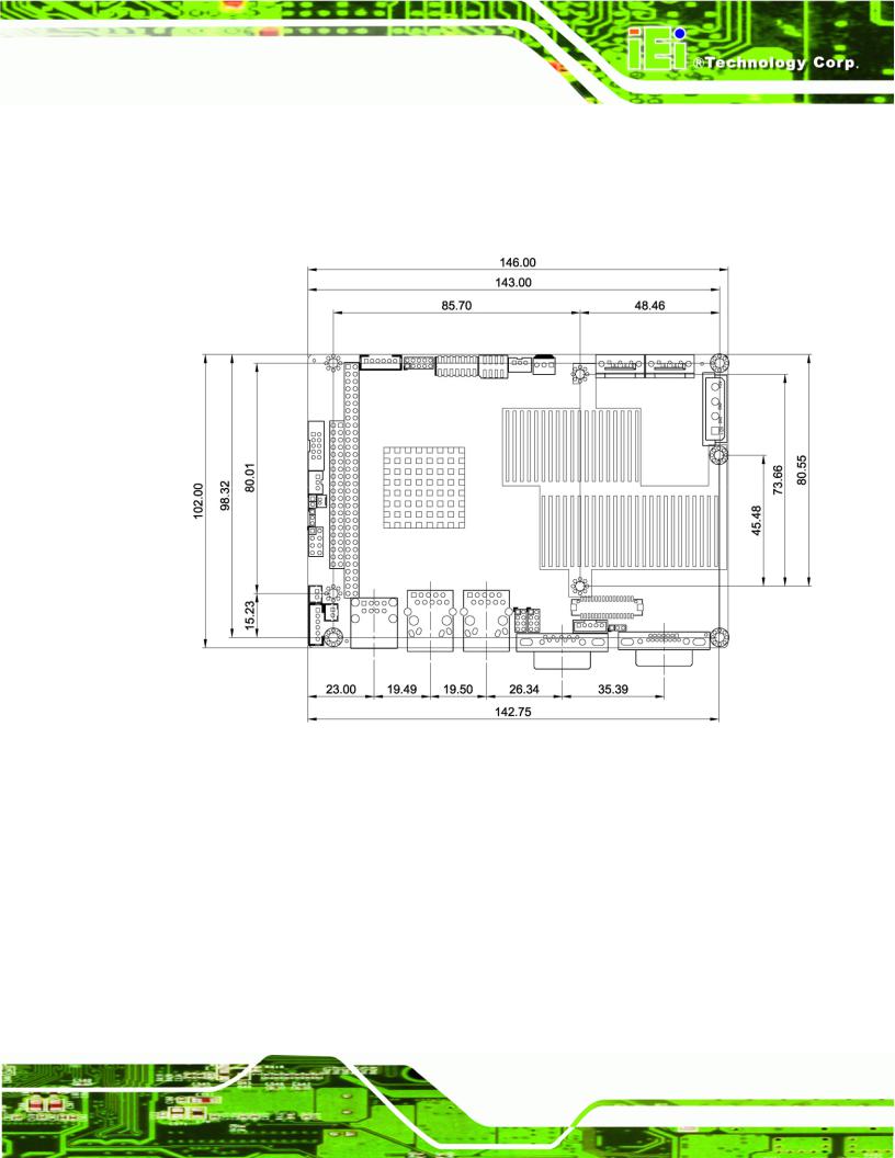
1.4Dimensions
1.4.1Board Dimensions
The dimensions of the board are shown below:
Page 5
WAFER-945GSE2 3.5" Motherboard
Figure 1-3: WAFER-945GSE2 Dimensions (mm)
1.4.2 External Interface Panel Dimensions
External peripheral interface connector panel dimensions are shown in Figure 1-4.
Figure 1-4: External Interface Panel Dimensions (mm)
Page 6
WAFER-945GSE2 3.5" Motherboard
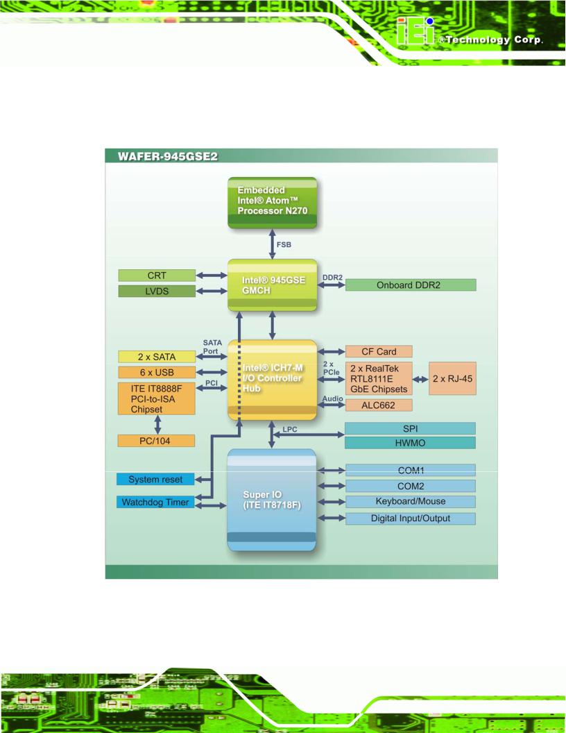
1.5 Data Flow
Figure6 1-5 shows the data flow between the system chipset, the CPU and other components installed on the motherboard.
Figure 1-5: Data Flow Diagram
Page 7

WAFER-945GSE2 3.5" Motherboard
1.6 Technical Specifications
The WAFER-945GSE2 technical specifications are listed below.
Specification/Model |
WAFER-945GSE2 |
|
|
Form Factor |
3.5” |
|
|
System CPU |
45 nm 1.6 GHz Intel® Atom™ N270 |
|
|
Front Side Bus |
533 MHz |
(FSB) |
|
|
|
System Chipset |
Northbridge: Intel® 945GSE |
|
Southbridge: Intel® ICH7-M |
|
|
Memory |
On-board 533 MHz 1.0 GB DDR2 SDRAM |
|
|
CompactFlash® |
One CompactFlash® Type II socket |
|
|
Super I/O |
ITE IT8718 |
|
|
Display |
Intel® Generation 3.5 integrated GFX core (133 MHz) |
|
18-bit dual channel LVDS integrated in Intel® 945GSE |
|
Dual-display supported (VGA and LVDS) |
|
|
BIOS |
AMI BIOS label |
|
|
Audio |
Realtek ALC662 HD Audio codec |
|
|
LAN |
Two Realtek RTL8111E GbE controllers with ASF2.0 support |
|
|
COM |
One RS-232 serial port |
|
One RS-232/422/485 serial port connector |
|
|
USB 2.0 |
Six USB 2.0 devices supported: |
|
Four by on-board pin-headers |
|
Two by external connectors |
|
|
SATA |
Two 3.0 Gb/s SATA drives supported |
|
|
Keyboard/mouse |
One internal pin-header connector |
|
|
Expansion |
One PC/104 ISA slot (ISA DMA Mode not supported) |
|
|
Digital I/O |
One 8-bit digital input/output connector; 4-bit input/4-bit output through |
|
the ITE IT8718 super I/O |
|
|
Page 8

WAFER-945GSE2 3.5" Motherboard
Specification/Model |
WAFER-945GSE2 |
|
|
Watchdog Timer |
Software programmable supports 1~255 sec. system reset |
|
|
Power Supply |
5 V only |
|
12 V for LCD/system fan |
|
AT and ATX support |
|
|
Power |
5V @ 3.1 A (1.6 GHz Intel® Atom™ N270 with on-board 1.0 GB DDR2 |
Consumption |
SDRAM) |
|
|
Temperature |
0ºC ~ 60ºC (WAFER-945GSE2-N270-R20) |
|
-20ºC ~ 70ºC (WAFER-945GSE2-N270W-R20) |
|
|
Humidity (operating) |
5% ~ 95% (non-condensing) |
|
|
Dimensions (LxW) |
146 mm x 102 mm |
|
|
Weight (GW/NW) |
700 g/230 g |
|
|
Table 1-2: WAFER-945GSE2 Specifications
Page 9

WAFER-945GSE2 3.5" Motherboard
Chapter
2
Packing List
Page 10

WAFER-945GSE2 3.5" Motherboard
2.1 Anti-static Precautions
 WARNING!
Static electricity can destroy certain electronics. Make sure to follow the ESD precautions to prevent damage to the product, and injury to the user.
Make sure to adhere to the following guidelines:
Wear an anti-static wristband: Wearing an anti-static wristband can prevent electrostatic discharge.
Self-grounding: Touch a grounded conductor every few minutes to discharge any excess static buildup.
Use an anti-static pad: When configuring any circuit board, place it on an anti-static mat.
Only handle the edges of the PCB: Don't touch the surface of the motherboard. Hold the motherboard by the edges when handling.
2.2 Unpacking Precautions
When the WAFER-945GSE2 is unpacked, please do the following:
Follow the antistatic guidelines above.
Make sure the packing box is facing upwards when opening.
Make sure all the packing list items are present.
Page 11
WAFER-945GSE2 3.5" Motherboard
2.3 Packing List
 NOTE:
NOTE:
If any of the components listed in the checklist below are missing, do not proceed with the installation. Contact the IEI reseller or vendor the WAFER-945GSE2 was purchased from or contact an IEI sales representative directly by sending an email to sales@iei32 .com.tw.
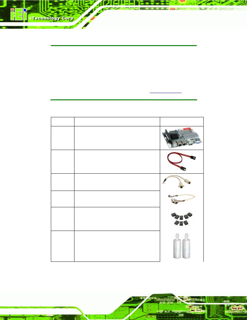
The WAFER-945GSE2 is shipped with the following components:
Quantity Item and Part Number |
Image |
1WAFER-945GSE2 motherboard
2SATA cable
(P/N: 32000-062800-RS)
1KB/MS Cable
(P/N: 32000-023800-RS)
1Audio cable
(P/N: 32000-072100-RS)
1Mini jumper pack (2.0mm) (P/N:33100-000033-RS)
2Plastic intermediate pole for PC/104 (15mm)
Page 12
WAFER-945GSE2 3.5" Motherboard
Quantity |
Item and Part Number |
Image |
|
|
|
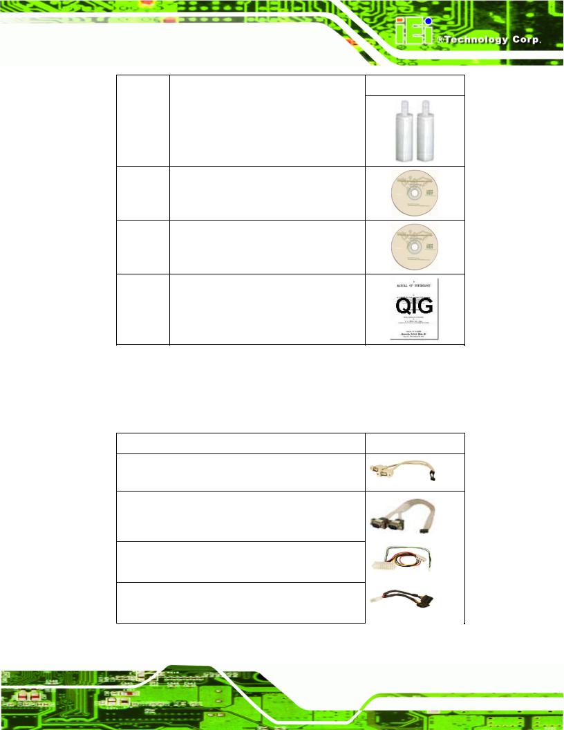
2 |
Plastic intermediate pole for PC/104 (20mm) |
|
1One Key Recovery CD (P/N: IEI-7B000-000478-RS)
1 |
Utility CD |
1 |
Quick Installation Guide |
Table 2-1: Packing List
2.4 Optional Items
The following are optional components which may be separately purchased:
Item and Part Number |
Image |
Dual USB cable (wo bracket) (P/N: 32000-070301-RS)
RS-232/422/485 cable (P/N:32200-026500-RS)
ATX power cable
(P/N: 32100-052100-RS)
SATA power cable
(P/N: 32100-088600-RS)
Table 2-2: Optional Items
Page 13
WAFER-945GSE2 3.5" Motherboard
Chapter
3
Connectors
Page 14

WAFER-945GSE2 3.5" Motherboard
3.1 Peripheral Interface Connectors
This chapter details all the jumpers and connectors.
3.1.1 WAFER-945GSE2 Layout
The figures below show all the connectors and jumpers.
Figure 3-1: Connectors and Jumpers (Front Side)
Figure 3-2: Connectors and Jumpers (Solder Side)
Page 15
Loading...