


 Loading...
Mini-ITX Motherboard
KINO-9453 Motherboard User Manual
IEI Technology Corp.
MODEL:
KINO-9453
Mini-ITX SBC with Intel® Core 2 Duo Processor
VGA/DVI, Dual GbE, USB 2.0, SATA, PCI and Audio
RoHS Compliant
User Manual
Rev. 2.10 – 13 December, 2010

KINO-9453 Mini-ITX Motherboard
|
|
|
Revision |
|
|
|
|
|
|
|
|
|
|
|
|
Date |
Version |
Changes |
|
|
|
|
|
|
|
13 December, 2010 |
v2.10 |
Updated for R21 version (deleted Mini PCI slot) |
|
|
|
|
|
|
|
3 December, 2010 |
v2.02 |
Added COM1 and COM2 location diagram in Section 4.3.6 |
|
|
|
|
|
|
|
13 August, 2009 |
v2.01 |
Deleted RAID information |
|
|
|
|
|
|
|
July, 2008 |
v2.00 |
-Changed Northbridge chipset from Intel® 945GM to Intel® 945GME |
|
|
|
|
-Added system fan connector (SYS_FAN1) information |
|
|
|
|
-Added four jumper information: |
|
|
|
|
x AT/ATX power mode select jumpers |
|
|
|
|
x LVDS screen resolution select jumper |
|
|
|
|
x COM3 mode select jumpers |
|
|
|
|
x RS-422/485 terminal resister jumpers |
|
|
|
|
|
|
|
April, 2007 |
v1.00 |
Initial Release |
|
|
|
|
|
|
Page II
KINO-9453 Mini-ITX Motherboard
Copyright
COPYRIGHT NOTICE
The information in this document is subject to change without prior notice in order to improve reliability, design and function and does not represent a commitment on the part of the manufacturer.
In no event will the manufacturer be liable for direct, indirect, special, incidental, or consequential damages arising out of the use or inability to use the product or documentation, even if advised of the possibility of such damages.
This document contains proprietary information protected by copyright. All rights are reserved. No part of this manual may be reproduced by any mechanical, electronic, or other means in any form without prior written permission of the manufacturer.
TRADEMARKS
All registered trademarks and product names mentioned herein are used for identification purposes only and may be trademarks and/or registered trademarks of their respective owners.
Page III
KINO-9453 Mini-ITX Motherboard
Manual Conventions
 WARNING!
Warnings appear where overlooked details may cause damage to the equipment or result in personal injury. Warnings should be taken seriously. Warnings are easy to recognize. The word “warning” is written as “WARNING,” both capitalized and bold and is followed by text. The text is the warning message. A warning message is shown below:
 WARNING:
This is an example of a warning message. Failure to adhere to warning messages may result in permanent damage to the KINO-9453 or personal injury to the user. Please take warning messages seriously.
 CAUTION!
Cautionary messages should also be heeded to help reduce the chance of losing data or damaging the KINO-9453. Cautions are easy to recognize. The word “caution” is written as “CAUTION,” both capitalized and bold and is followed. The italicized text is the cautionary message. A caution message is shown below:
Page IV

KINO-9453 Mini-ITX Motherboard
 CAUTION:
This is an example of a caution message. Failure to adhere to cautions messages may result in permanent damage to the KINO-9453. Please take caution messages seriously.
 NOTE:
NOTE:
These messages inform the reader of essential but non-critical information. These messages should be read carefully as any directions or instructions contained therein can help avoid making mistakes. Notes are easy to recognize. The word “note” is written as “NOTE,” both capitalized and bold and is followed by text. The text is the cautionary message. A note message is shown below:
 NOTE:
NOTE:
This is an example of a note message. Notes should always be read. Notes contain critical information about the KINO-9453. Please take note messages seriously.
Page V
KINO-9453 Mini-ITX Motherboard
Packing List
 NOTE:
NOTE:
If any of the components listed in the checklist below are missing, please do not proceed with the installation. Contact the IEI reseller or vendor you purchased the KINO-9453 from or contact an IEI sales representative directly. To contact an IEI sales representative, please send an email to sales@iei.com.tw.
The items listed below should all be included in the KINO-9453 package.
1 x KINO-9453 single board computer
1 x IDE cable
1 x SATA power cable
2 x SATA cables
1 x Dual RS-232 cable
1 x I/O shielding
1 x Mini jumper pack
1 x Utility CD
1 x QIG (quick installation guide)
Images of the above items are shown in Chapter 3.
Page VI
KINO-9453 Mini-ITX Motherboard
|
Table of Contents |
|
1 |
INTRODUCTION..................................................................................................... |
1 |
|
1.1 INTRODUCTION........................................................................................................... |
2 |
|
1.1.1 KINO-9453 Benefits........................................................................................... |
3 |
|
1.1.2 KINO-9453 Features.......................................................................................... |
3 |
|
1.2 KINO-9453 OVERVIEW ............................................................................................. |
3 |
|
1.2.1 KINO-9453 Overview Photo.............................................................................. |
3 |
|
1.2.2 KINO-9453 Peripheral Connectors and Jumpers ............................................. |
4 |
|
1.2.3 Technical Specifications..................................................................................... |
5 |
2 |
DETAILED SPECIFICATIONS ............................................................................. |
8 |
|
2.1 OVERVIEW.................................................................................................................. |
9 |
|
2.2 DIMENSIONS............................................................................................................... |
9 |
|
2.2.1 Board Dimensions.............................................................................................. |
9 |
|
2.2.2 External Interface Panel Dimensions .............................................................. |
10 |
|
2.3 DATA FLOW ............................................................................................................... |
11 |
|
2.4 COMPATIBLE PROCESSORS ....................................................................................... |
12 |
|
2.4.1 Compatible Processor Overview ..................................................................... |
12 |
|
2.4.2 Supported Processors ...................................................................................... |
12 |
|
2.5 INTEL® 945GME NORTHBRIDGE CHIPSET................................................................ |
13 |
|
2.5.1 Intel® 945GME Overview ................................................................................ |
13 |
|
2.5.2 Intel® 945GME Memory Support..................................................................... |
13 |
|
2.5.3 Intel® 945GME Integrated Graphics ............................................................... |
14 |
|
2.5.3.1 Intel® 945GME Analog CRT Support....................................................... |
15 |
|
2.5.3.2 Intel® 945GME LVDS Support................................................................. |
15 |
|
2.5.3.3 Intel® 945GME SDVO Support................................................................ |
15 |
|
2.5.4 Intel® 945GME Direct Media Interface (DMI)................................................ |
15 |
|
2.6 INTEL® ICH7-M SOUTHBRIDGE CHIPSET ................................................................. |
16 |
|
2.6.1 Intel® ICH7-M Overview ................................................................................. |
16 |
|
2.6.2 Intel® ICH7-M Audio Codec ’97 Controller.................................................... |
16 |
|
2.6.3 Intel® ICH7-M IDE Interface........................................................................... |
17 |
|
2.6.4 Intel® ICH7-M Low Pin Count (LPC) Interface.............................................. |
17 |
Page VII

|
KINO-9453 Mini-ITX Motherboard |
|
|
2.6.5 Intel® ICH7-M PCI Interface........................................................................... |
18 |
|
2.6.6 Intel® ICH7-M Real Time Clock ...................................................................... |
18 |
|
2.6.7 Intel® ICH7-M SATA Controller ...................................................................... |
18 |
|
2.6.8 Intel® ICH7-M USB Controller........................................................................ |
18 |
|
2.7 PCIE BUS COMPONENTS .......................................................................................... |
19 |
|
2.7.1 PCIe Bus Overview .......................................................................................... |
19 |
|
2.7.2 Broadcom PCI Express GbE interface............................................................. |
19 |
|
2.8 LPC BUS COMPONENTS ........................................................................................... |
19 |
|
2.8.1 LPC Bus Overview........................................................................................... |
19 |
|
2.8.2 BIOS Chipset.................................................................................................... |
20 |
|
2.8.3 Super I/O chipset.............................................................................................. |
20 |
|
2.8.3.1 Super I/O LPC Interface ........................................................................... |
21 |
|
2.8.3.2 Super I/O 16C550 UARTs ........................................................................ |
21 |
|
2.8.3.3 Super I/O Enhanced Hardware Monitor ................................................... |
21 |
|
2.8.3.4 Super I/O Fan Speed Controller................................................................ |
21 |
|
2.8.3.5 Super I/O Keyboard Controller................................................................. |
21 |
|
2.9 ENVIRONMENTAL AND POWER SPECIFICATIONS ....................................................... |
22 |
|
2.9.1 System Monitoring ........................................................................................... |
22 |
|
2.9.2 Operating Temperature and Temperature Control........................................... |
23 |
|
2.9.3 Power Consumption......................................................................................... |
23 |
3 |
UNPACKING .......................................................................................................... |
24 |
|
3.1 ANTI-STATIC PRECAUTIONS ...................................................................................... |
25 |
|
3.2 UNPACKING.............................................................................................................. |
25 |
|
3.2.1 Unpacking Precautions.................................................................................... |
25 |
|
3.3 UNPACKING CHECKLIST ........................................................................................... |
26 |
|
3.3.1 Package Contents............................................................................................. |
26 |
|
3.3.2 Optional Items.................................................................................................. |
27 |
4 |
CONNECTOR PINOUTS...................................................................................... |
29 |
|
4.1 PERIPHERAL INTERFACE CONNECTORS..................................................................... |
30 |
|
4.1.1 KINO-9453 Layout........................................................................................... |
30 |
|
4.1.2 Peripheral Interface Connectors ..................................................................... |
31 |
|
4.1.3 External Interface Panel Connectors............................................................... |
32 |
|
4.2 INTERNAL PERIPHERAL CONNECTORS ...................................................................... |
32 |
Page VIII

KINO-9453 Mini-ITX Motherboard |
|
4.2.1 Fan Connectors................................................................................................ |
32 |
4.2.2 Front Panel Connector .................................................................................... |
33 |
4.2.3 Digital Input/Output Connector....................................................................... |
34 |
4.2.4 IDE Connector ................................................................................................. |
35 |
4.2.5 LCD Backlight Connector................................................................................ |
37 |
4.2.6 LVDS LCD connector ...................................................................................... |
38 |
4.2.7 Power Connector ............................................................................................. |
40 |
4.2.8 14-Pin Serial Port Connectors......................................................................... |
41 |
4.2.9 10-Pin Serial Port Connectors......................................................................... |
42 |
4.2.10 SATA Drive Connectors ................................................................................. |
42 |
4.2.11 SPDIF Connector........................................................................................... |
43 |
4.2.12 Internal USB Connectors............................................................................... |
44 |
4.3 EXTERNAL INTERFACE CONNECTORS ....................................................................... |
45 |
4.3.1 Audio Connectors............................................................................................. |
46 |
4.3.2 CRT Connector ................................................................................................ |
47 |
4.3.3 DVI Connector ................................................................................................. |
47 |
4.3.4 Ethernet Connectors ........................................................................................ |
48 |
4.3.5 Keyboard/Mouse Connector ............................................................................ |
50 |
4.3.6 Serial Port Connectors .................................................................................... |
51 |
4.3.7 USB Connector ................................................................................................ |
52 |
5 INSTALLATION .................................................................................................... |
53 |
5.1 ANTI-STATIC PRECAUTIONS ...................................................................................... |
54 |
5.2 INSTALLATION CONSIDERATIONS.............................................................................. |
55 |
5.2.1 Installation Notices .......................................................................................... |
55 |
5.2.2 Installation Checklist ....................................................................................... |
56 |
5.3 CPU, CPU COOLING KIT AND DIMM INSTALLATION .............................................. |
57 |
5.3.1 Socket 479 CPU Installation............................................................................ |
57 |
5.3.2 Cooling Kit CF-479B-RS Installation.............................................................. |
60 |
5.3.3 DIMM Installation ........................................................................................... |
62 |
5.4 JUMPER SETTINGS .................................................................................................... |
63 |
5.4.1 AT/ATX Power Select Jumper Settings ............................................................ |
64 |
5.4.2 Clear CMOS Jumper........................................................................................ |
65 |
5.4.3 COM 3 Function Select Jumper....................................................................... |
67 |
5.4.4 RS-422 or RS-486 Termination Resister .......................................................... |
68 |
Page IX

KINO-9453 Mini-ITX Motherboard |
|
5.4.5 LVDS Screen Resolution Selection................................................................... |
69 |
5.4.6 LVDS Voltage Selection.................................................................................... |
71 |
5.5 CHASSIS INSTALLATION............................................................................................ |
73 |
5.5.1 Airflow.............................................................................................................. |
73 |
5.5.2 Motherboard Installation................................................................................. |
73 |
5.6 INTERNAL PERIPHERAL DEVICE CONNECTIONS........................................................ |
74 |
5.6.1 Peripheral Device Cables ................................................................................ |
74 |
5.6.2 IDE Cable Connection..................................................................................... |
74 |
5.6.3 Dual RS-232 Cable Connection....................................................................... |
75 |
5.6.4 SATA Drive Connection ................................................................................... |
76 |
5.7 EXTERNAL PERIPHERAL INTERFACE CONNECTION ................................................... |
78 |
5.7.1 Audio Connection............................................................................................. |
78 |
5.7.2 RJ-45 Ethernet Connection.............................................................................. |
79 |
5.7.3 USB Connection............................................................................................... |
80 |
5.7.4 VGA Monitor Connection ................................................................................ |
81 |
5.7.5 Serial Device Connection ................................................................................ |
82 |
5.7.6 PS/2 Keyboard/Mouse Connection .................................................................. |
83 |
6 AMI BIOS................................................................................................................ |
85 |
6.1 INTRODUCTION......................................................................................................... |
86 |
6.1.1 Starting Setup................................................................................................... |
86 |
6.1.2 Using Setup ...................................................................................................... |
86 |
6.1.3 Getting Help..................................................................................................... |
87 |
6.1.4 Unable to Reboot After Configuration Changes.............................................. |
87 |
6.1.5 BIOS Menu Bar................................................................................................ |
87 |
6.2 MAIN........................................................................................................................ |
88 |
6.3 ADVANCED ............................................................................................................... |
89 |
6.3.1 CPU Configuration.......................................................................................... |
90 |
6.3.2 IDE Configuration ........................................................................................... |
91 |
6.3.2.1 IDE Master, IDE Slave ............................................................................. |
94 |
6.3.3 Super IO Configuration ................................................................................... |
98 |
6.3.4 Hardware Health Configuration.................................................................... |
102 |
6.3.5 ACPI Configuration ....................................................................................... |
107 |
6.3.5.1 General ACPI Configuration................................................................... |
107 |
6.3.6 APM Configuration........................................................................................ |
109 |
Page X
KINO-9453 Mini-ITX Motherboard |
|
|
|
6.3.7 Remote Access Configuration ......................................................................... |
111 |
|
6.3.8 USB Configuration.......................................................................................... |
115 |
|
6.3.8.1 USB Mass Storage Device Configuration................................................ |
118 |
|
6.4 PCI/PNP................................................................................................................. |
120 |
|
6.5 BOOT...................................................................................................................... |
126 |
|
6.5.1 Boot Settings Configuration........................................................................... |
127 |
|
6.5.2 Boot Device Priority ...................................................................................... |
129 |
|
6.5.3 Removable Drives .......................................................................................... |
131 |
|
6.6 SECURITY............................................................................................................... |
132 |
|
6.7 CHIPSET ................................................................................................................. |
133 |
|
6.7.1 NorthBridge Configuration............................................................................ |
134 |
|
6.7.1.1 Video Function Configuration ................................................................ |
135 |
|
6.7.2 SouthBridge Chipset Configuration............................................................... |
138 |
|
6.8 EXIT ....................................................................................................................... |
140 |
7 |
DRIVER INSTALLATION.................................................................................. |
142 |
|
7.1 AVAILABLE SOFTWARE DRIVERS ............................................................................ |
143 |
|
7.2 DRIVER CD AUTO-RUN .......................................................................................... |
143 |
|
7.3 CHIPSET DRIVER INSTALLATION............................................................................. |
144 |
|
7.4 INTEL GRAPHICS MEDIA ACCELERATOR DRIVER.................................................... |
149 |
|
7.5 BROADCOM LAN DRIVER (FOR GBE LAN) INSTALLATION ................................... |
155 |
|
7.6 REALTEK AC`97 AUDIO DRIVER (ALC655) INSTALLATION ................................... |
161 |
|
7.6.1 BIOS Setup ..................................................................................................... |
161 |
|
7.6.2 Driver Installation ......................................................................................... |
161 |
A |
BIOS OPTIONS.................................................................................................... |
167 |
B |
DIO INTERFACE................................................................................................. |
171 |
|
B.1 DIO INTERFACE INTRODUCTION............................................................................ |
172 |
|
B.2 DIO CONNECTOR PINOUTS.................................................................................... |
172 |
|
B.3 ASSEMBLY LANGUAGE SAMPLES........................................................................... |
173 |
|
B.3.1 Enable the DIO Input Function..................................................................... |
173 |
|
B.3.2 Enable the DIO Output Function .................................................................. |
173 |
C |
WATCHDOG TIMER .......................................................................................... |
174 |
Page XI

KINO-9453 Mini-ITX Motherboard
List of Figures |
|
Figure 1-1: KINO-9453 Embedded SBC........................................................................................ |
2 |
Figure 1-2: KINO-9453 Overview ................................................................................................... |
4 |
Figure 2-1: KINO-9453 Dimensions (mm)..................................................................................... |
9 |
Figure 2-2: External Interface Panel Dimensions (mm)............................................................ |
10 |
Figure 2-3: Data Flow Block Diagram ......................................................................................... |
11 |
Figure 2-4: 240-pin DIMM Sockets .............................................................................................. |
14 |
Figure 4-1: Connector and Jumper Locations........................................................................... |
30 |
Figure 4-2: Fan Connector Locations......................................................................................... |
33 |
Figure 4-3: Front Panel Connector Location ............................................................................. |
34 |
Figure 4-4: GPIO Connector Location ........................................................................................ |
35 |
Figure 4-5: IDE Device Connector Location .............................................................................. |
36 |
Figure 4-6: LCD Backlight Connector Location ........................................................................ |
38 |
Figure 4-7: LVDS LCD Connector Location ............................................................................... |
39 |
Figure 4-8: Power Connector Location ...................................................................................... |
40 |
Figure 4-9: 14-Pin Serial Port Connector Locations ................................................................. |
41 |
Figure 4-10: 10-Pin Serial Port Connector Locations ............................................................... |
42 |
Figure 4-11: SATA Drive Connector Locations .......................................................................... |
43 |
Figure 4-12: SPDIF Connector Locations .................................................................................. |
44 |
Figure 4-13: Internal USB Connector Locations ....................................................................... |
45 |
Figure 4-14: KINO-9453 External Interface Connectors............................................................ |
46 |
Figure 4-15: Audio Connectors ................................................................................................... |
46 |
Figure 4-16: VGA Connector........................................................................................................ |
47 |
Figure 4-17 DVI-I Connector Pinout Locations.......................................................................... |
48 |
Figure 4-18: RJ-45 Ethernet Connector...................................................................................... |
49 |
Figure 4-19: PS/2 Pinouts ............................................................................................................ |
50 |
Figure 4-20: External Serial Port Connector.............................................................................. |
51 |
Figure 5-1: Make sure the CPU socket retention screw is unlocked ...................................... |
58 |
Figure 5-2: Lock the CPU Socket Retention Screw................................................................... |
59 |
Figure 5-3: IEI CF-479B-RS Cooling Kit...................................................................................... |
60 |
Figure 5-4: Cooling Kit Support Bracket.................................................................................... |
61 |
Figure 5-5: Connect the cooling fan cable................................................................................. |
61 |
Page XII
KINO-9453 Mini-ITX Motherboard
Figure 5-6: Installing a DIMM....................................................................................................... |
62 |
Figure 5-7: Jumper Locations ..................................................................................................... |
63 |
Figure 5-8: AT/ATX Power Select Jumper Location .................................................................. |
65 |
Figure 5-9: Clear CMOS Jumper ................................................................................................. |
66 |
Figure 5-10: COM 3 Function Select Jumper Locations........................................................... |
68 |
Figure 5-11: RS-422 and RS-485 Termination Resister Jumper Locations............................. |
69 |
Figure 5-12: LVDS Screen Resolution Selection Jumper Pinout Locations........................... |
71 |
Figure 5-13: LVDS Voltage Selection Jumper Pinout Locations.............................................. |
72 |
Figure 5-14: IDE Cable Connection............................................................................................. |
75 |
Figure 5-15: Dual RS-232 Cable Installation .............................................................................. |
76 |
Figure 5-16: SATA Drive Cable Connection ............................................................................... |
77 |
Figure 5-17: SATA Power Drive Connection .............................................................................. |
77 |
Figure 5-18: Audio Connectors ................................................................................................... |
79 |
Figure 5-19: RJ-45 Ethernet Connector...................................................................................... |
80 |
Figure 5-20: USB Connector........................................................................................................ |
81 |
Figure 5-21: VGA Connector........................................................................................................ |
82 |
Figure 5-22: Serial Device Connector......................................................................................... |
83 |
Figure 5-23: PS/2 Keyboard/Mouse Connector ......................................................................... |
84 |
Figure 6-1: Video Function Configuration............................................................................... |
136 |
Figure 7-1: Available Drivers .................................................................................................... |
144 |
Figure 7-2: Chipset Driver Installation Program..................................................................... |
145 |
Figure 7-3: Chipset Driver Installation Welcome Screen....................................................... |
146 |
Figure 7-4: Chipset Driver Installation License Agreement .................................................. |
147 |
Figure 7-5: Chipset Driver Readme File Information ............................................................. |
148 |
Figure 7-6: Chipset Driver Installation Complete ................................................................... |
149 |
Figure 7-7: Select the Operating System ................................................................................ |
150 |
Figure 7-8: VGA Driver .............................................................................................................. |
151 |
Figure 7-9: GMA Driver Readme File ....................................................................................... |
152 |
Figure 7-10: GMA Driver File Extraction.................................................................................. |
152 |
Figure 7-11: GMA Driver Installation Welcome Screen.......................................................... |
153 |
Figure 7-12: GMA Driver License Agreement ......................................................................... |
154 |
Figure 7-13: GMA Driver Installing Notice............................................................................... |
154 |
Figure 7-14: GMA Driver Installation Complete ...................................................................... |
155 |
Figure 7-15: Access Windows Control Panel ......................................................................... |
156 |
Figure 7-16: Double Click the System Icon............................................................................. |
157 |
Page XIII

KINO-9453 Mini-ITX Motherboard |
|
Figure 7-17: Double Click the Device Manager Tab ............................................................... |
157 |
Figure 7-18: Device Manager List ............................................................................................ |
158 |
Figure 7-19: Search for Suitable Driver ................................................................................... |
159 |
Figure 7-20: Locate Driver Files ............................................................................................... |
160 |
Figure 7-21: Location Browsing Window ................................................................................ |
160 |
Figure 7-22: AC`97 Audio Driver Install Shield Wizard Starting............................................ |
161 |
Figure 7-23: AC`97 Audio Driver Setup Preparation .............................................................. |
162 |
Figure 7-24: AC`97 Audio Driver Welcome Screen................................................................. |
162 |
Figure 7-25: AC`97 Audio Driver Software Configuration ..................................................... |
163 |
Figure 7-26: AC`97 Audio Driver Digital Signal....................................................................... |
164 |
Figure 7-27: AC`97 Audio Driver Installation Begins ............................................................. |
165 |
Figure 7-28: AC`97 Audio Driver Installation Complete......................................................... |
166 |
Page XIV

KINO-9453 Mini-ITX Motherboard
List of Tables |
|
Table 1-1: Technical Specifications .............................................................................................. |
7 |
Table 2-1: Processor Features .................................................................................................... |
12 |
Table 2-2: Supported Processors ............................................................................................... |
13 |
Table 2-3: Supported HDD Specifications.................................................................................. |
17 |
Table 2-4: Power Consumption ................................................................................................... |
23 |
Table 2-5: Power Consumption ................................................................................................... |
23 |
Table 3-1: Package List Contents................................................................................................ |
27 |
Table 3-2: Optional Items ............................................................................................................. |
28 |
Table 4-1: Peripheral Interface Connectors ............................................................................... |
31 |
Table 4-2: Rear Panel Connectors .............................................................................................. |
32 |
Table 4-3: Fan Connector Pinouts............................................................................................... |
33 |
Table 4-4: Front Panel Connector Pinouts ................................................................................. |
34 |
Table 4-5: GPIO Connector Pinouts............................................................................................ |
35 |
Table 4-6: IDE Connector Pinouts............................................................................................... |
37 |
Table 4-7: LCD Backlight Connector Pinouts ............................................................................ |
38 |
Table 4-8: LVDS LCD Connector Pinouts ................................................................................... |
39 |
Table 4-9: Power Connector Pinouts .......................................................................................... |
40 |
Table 4-10: COM2 Pinouts............................................................................................................ |
41 |
Table 4-11: COM4 Pinouts............................................................................................................ |
42 |
Table 4-12: SATA Drive Connector Pinouts................................................................................ |
43 |
Table 4-13: SPDIF Pinouts ........................................................................................................... |
44 |
Table 4-14: USB3 and USB4 Pinouts .......................................................................................... |
45 |
Table 4-15: VGA Connector Pinouts ........................................................................................... |
47 |
Table 4-16: DVI-I Connector Pinouts........................................................................................... |
48 |
Table 4-17: LAN1 and LAN2 Pinouts........................................................................................... |
49 |
Table 4-18: RJ-45 Ethernet Connector LEDs ............................................................................. |
49 |
Table 4-19: PS/2 Connector Pinouts ........................................................................................... |
50 |
Table 4-20: External Serial Port Pinouts..................................................................................... |
51 |
Table 4-21: External USB Connector Pinouts ............................................................................ |
52 |
Table 5-1: Jumpers ....................................................................................................................... |
64 |
Page XV

KINO-9453 Mini-ITX Motherboard |
|
Table 5-2: AT/ATX Power Select Jumper Settings..................................................................... |
64 |
Table 5-3: Clear CMOS Jumper Settings.................................................................................... |
66 |
Table 5-4: COM 3 Function Select Jumper Settings ................................................................. |
67 |
Table 5-5: RS-422 Termination Resister Jumper Settings........................................................ |
68 |
Table 5-6: RS-485 Termination Resister Jumper Settings........................................................ |
69 |
Table 5-7: LVDS Screen Resolution Selection Jumper Settings.............................................. |
70 |
Table 5-8: LVDS Voltage Selection Jumper Settings................................................................. |
72 |
Table 5-9: IEI Provided Cables .................................................................................................... |
74 |
Table 6-1: BIOS Navigation Keys ................................................................................................ |
87 |
Page XVI

KINO-9453 Mini-ITX Motherboard
BIOS Menus |
|
Menu 1: Main ................................................................................................................................. |
88 |
Menu 2: Advanced ........................................................................................................................ |
90 |
Menu 3: CPU Configuration......................................................................................................... |
91 |
Menu 4: IDE Configuration........................................................................................................... |
92 |
Menu 5: IDE Master and IDE Slave Configuration..................................................................... |
94 |
Menu 6: Super IO Configuration ................................................................................................. |
99 |
Menu 7: Hardware Health Configuration................................................................................. |
102 |
Menu 8: ACPI Configuration ..................................................................................................... |
107 |
Menu 9: General ACPI Configuration [Advanced\ ACPI Configuration] .............................. |
108 |
Menu 10:Advanced Power Management Configuration ........................................................ |
109 |
Menu 11: Remote Access Configuration [Advanced] ............................................................. |
112 |
Menu 12: USB Configuration..................................................................................................... |
116 |
Menu 13: USB Mass Storage Device Configuration ................................................................ |
118 |
Menu 14: PCI/PnP Configuration ............................................................................................. |
121 |
Menu 15: Boot ............................................................................................................................ |
126 |
Menu 16: Boot Settings Configuration.................................................................................... |
127 |
Menu 17: Boot Device Priority Settings .................................................................................. |
130 |
Menu 18: Removable Drives..................................................................................................... |
131 |
Menu 19: Security...................................................................................................................... |
132 |
Menu 20: Chipset ....................................................................................................................... |
133 |
Menu 21:NorthBridge Chipset Configuration ......................................................................... |
134 |
Menu 22:SouthBridge Chipset Configuration......................................................................... |
138 |
Menu 23:Exit............................................................................................................................... |
140 |
Page XVII
KINO-9453 Mini-ITX Motherboard
Chapter
1
Introduction
Page 1
KINO-9453 Mini-ITX Motherboard
1.1 Introduction
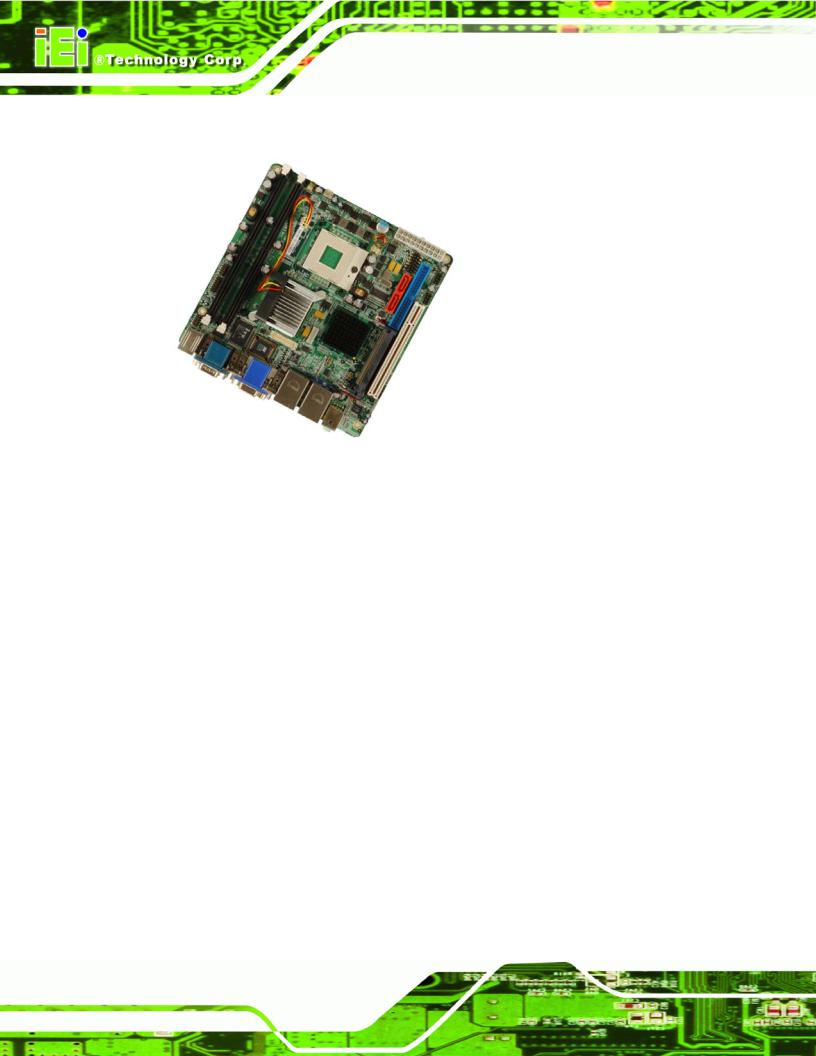
Figure 1-1: KINO-9453 Embedded SBC
The KINO-9453 Mini-ITX form factor motherboard is an Intel® dual-core CPU platform. Intel® Core™2 Duo, Core Duo and Core Solo CPU are all supported to enhance the system processing speed. The KINO-9452 has a maximum front side bus (FSB) frequency of 667 MHz and contains two DDR2 SDRAM DIMM sockets that support up to 4 GB system memory.
The KINO-9453 supports diverse displays including one VGA display, one DVI display and one LVDS display. These multimedia features make the KINO-9453 a best choice for integrating into point-of-sale (POS), kiosk or digital signage applications.
The KINO-9453 supports up to two serial ATA (SATA) hard disk drives (HDD) with maximum transfer rates of 1.5 Gb/s and up to eight USB 2.0 devices. The dual PCI Express (PCIe) Gigabit Ethernet (GbE) controllers provide GbE connectivity for network communication. The KINO-9453 also has a PCI socket for system expansion. Three RS-232, one RS-232/422/485 and one digital input/output (DIO) port offer system integrators more choices of peripheral devices for the targeted application.
Page 2

KINO-9453 Mini-ITX Motherboard
1.1.1 KINO-9453 Benefits
Some of the KINO-9453 benefits are listed below:
Multiple display output options
Storage flexibility with support for SATA drives and IDE drives Expandable system with PCI slot
DDR2 support enables faster data transfers
Multiple I/O interfaces provide connectivity to a broad range of external peripheral devices
1.1.2 KINO-9453 Features
Some of the KINO-9453 features are listed below.
Support for Socket 479 Intel® Core 2 Duo or Core Solo CPUs Maximum FSB of 667 MHz
Supports two 240-pin 400 MHz, 533 MHz or 667 MHz 2GB DDR2 DIMM memory modules
Two SATA drives with transfer rates of 1.5 Gb/s supported
Two Ultra ATA 100, Ultra ATA 66 or Ultra ATA 33 IDE HDDs supported Eight USB 2.0 devices supported
Dual PCIe GbE Ethernet connectivity
Multiple display options including CRT, DVI and dual-channel LVDS Mini-ITX form factor
RoHS compliant
Supports AT and ATX power supplies
1.2KINO-9453 Overview
1.2.1KINO-9453 Overview Photo
The KINO-9453 has a wide variety of internal and external peripheral connectors. The peripheral connectors are connected to devices including PCI devices, storage devices, display devices and serial communications devices. A labeled photo of the peripheral connectors on the front of the KINO-9453 is shown in Figure 1-2.
Page 3
KINO-9453 Mini-ITX Motherboard
Figure 1-2: KINO-9453 Overview
1.2.2 KINO-9453 Peripheral Connectors and Jumpers
The KINO-9453 has the following connectors on-board:
2 x DDR2 DIMM sockets
1 x Digital I/O connector
3 x Fan connectors
1 x Front panel connector
1 x IDE Interface connector
1 x LCD backlight connector
1 x LVDS LCD connector
1 x PCI slot
1 x Power connector
Page 4

KINO-9453 Mini-ITX Motherboard
2 x Serial port connectors
2 x SATA connectors
1 x SPDIF connector
2 x USB connectors
The KINO-9453 has the following external peripheral interface connectors on the board rear panel
2 x Audio jacks
1 x VGA connector
2 x Ethernet connectors
2 x Keyboard/Mouse connectors
2 x Serial port connectors
1 x DVI connector
4 x USB 2.0 ports
The KINO-9453 has the following on-board jumpers:
AT/ATX power mode selection
Clear CMOS
COM3 mode selection (RS-232/422/485)
RS-422 or RS-485 termination resister
LVDS LCD voltage selection
LVDS screen resolution selection
1.2.3 Technical Specifications
KINO-9453 technical specifications are listed in Table 1-1. See Chapter 2 for details.
Specification |
KINO-9453 |
|
|
|
|
Form Factor |
Mini-ITX |
|
|
|
|
|
Socket 479 |
Intel® Core™ 2 Duo Mobile |
System CPU |
Socket 479 |
Intel® Core™ Duo |
|
Socket 479 |
Intel® Core™ Solo |
|
|
|
Page 5
|
KINO-9453 Mini-ITX Motherboard |
|
|
|
|
Specification |
KINO-9453 |
|
|
|
|
|
Socket 479 Intel® Celeron® M FSB 533 MHz (socket M) |
|
Front Side Bus |
533 MHz or 667 MHz |
|
|
|
|
System Chipset |
Northbridge: Intel® 945GME |
|
Southbridge: Intel® ICH7-M |
||
|
||
Memory |
Two 240-pin 400 MHz, 533 MHz or 667 MHz DDR2 SDRAM |
|
DIMMs supported (system max. 4 GB) |
||
|
||
|
|
|
|
CRT: Integrated in the Intel® 945GME to support CRT |
|
Display |
DVI: Integrated in the Intel® 945GME by SDVO interface |
|
|
LVDS: Dual channel 18-bit or 24-bit LVDS LCD panel |
|
|
|
|
BIOS |
AMI BIOS |
|
|
|
|
Audio |
Realtek ALC655 with AC’97 codec |
|
|
|
|
LAN |
Two Broadcom BCM5787M PCIe GbE controllers |
|
|
|
|
COM |
Three RS-232 serial ports (one internal, two external) |
|
One RS-232, RS-422 or RS-485 serial port |
||
|
||
|
|
|
USB2.0 |
Eight USB 2.0 devices supported |
|
|
|
|
IDE |
One 40-pin IDE connects to two Ultra ATA33/66/100 devices |
|
|
|
|
SATA |
Two 1.5 Gb/s SATA drives supported |
|
|
|
|
Keyboard/mouse |
Two PS/2 connectors support mouse and keyboard |
|
connectivity |
||
|
||
|
|
|
Watchdog Timer |
Software programmable 1-255 sec. by super I/O |
|
|
|
|
Power Supply |
AT and ATX supported |
|
|
|
|
Temperature |
0ºC – 60ºC (32ºF - 140ºF) |
|
|
|
|
Humidity (operating) |
5%~95% non-condensing |
|
|
|
Page 6

KINO-9453 Mini-ITX Motherboard
Specification |
KINO-9453 |
|
|
Dimensions (LxW) |
170 mm x 170 mm |
|
|
Weight (GW/NW) |
900g/ 362g |
|
|
Table 1-1: Technical Specifications
Page 7
KINO-9453 Mini-ITX Motherboard
Chapter
2
Detailed Specifications
Page 8

KINO-9453 Mini-ITX Motherboard
2.1 Overview
This chapter describes the specifications and on-board features of the KINO-9453 in detail.
2.2Dimensions
2.2.1Board Dimensions
The dimensions of the board are listed below:
Length: |
170 mm |
Width: |
170 mm |
Figure 2-1: KINO-9453 Dimensions (mm)
Page 9
KINO-9453 Mini-ITX Motherboard
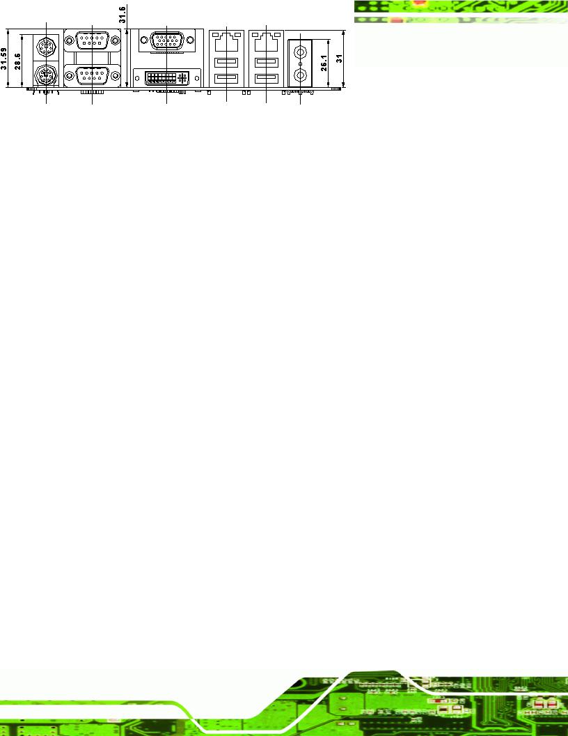
2.2.2 External Interface Panel Dimensions
External peripheral interface connector panel dimensions are shown in Figure 2-2.
Figure 2-2: External Interface Panel Dimensions (mm)
Page 10
KINO-9453 Mini-ITX Motherboard
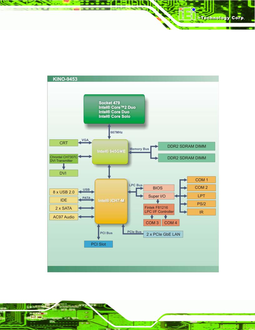
2.3 Data Flow
Figure 2-3 shows the data flow between the two on-board chipsets and other components installed on the motherboard and described in the following sections of this chapter.
Figure 2-3: Data Flow Block Diagram
Page 11

KINO-9453 Mini-ITX Motherboard
2.4Compatible Processors
2.4.1Compatible Processor Overview
The KINO-9453 supports the following socket 479 processors:
Intel® Core™2 Duo Mobile processors
Intel® Core™ Duo processors
Intel® Core™ Solo processors
Intel® Celeron® M processors
The first three of the above processors communicate with the Intel® 945GME GMCH through a 667 MHz FSB and the Intel® Celeron® M processor through a 533 MHz FSB. Features of the supported processors are listed in Table 2-1.
|
CPU Features |
|
|
|
Core™2 Duo |
|
Core™ Duo |
|
Core™ Solo |
Celeron® M |
||
|
|
|
|
|
|
|
|
|
|
|
||
|
Dual core |
|
|
|
Yes |
Yes |
|
No |
No |
|||
|
|
|
|
|
|
|
|
|
|
|||
|
Enhanced Halt State (C1E) |
|
|
No |
|
Yes |
|
No |
No |
|||
|
|
|
|
|
|
|
|
|
|
|
|
|
|
|
|
|
® |
® |
|
Yes |
|
Yes |
|
Yes |
No |
|
Enhanced Intel Speedstep |
|
Technolgy |
|
|
|||||||
|
|
|
|
|
|
|
|
|||||
|
Execute Disable Bit |
|
|
Yes |
|
Yes |
|
Yes |
Yes |
|||
|
|
|
|
|
|
|
|
|
|
|
|
|
|
Intel |
® |
EM64T |
|
|
|
Yes |
|
No |
|
No |
No |
|
|
|
|
|
|
|
||||||
|
|
|
|
|
|
|
|
|
|
|
||
|
Intel |
® |
Virtualization Technology |
Yes |
|
Yes |
|
No |
No |
|||
|
|
|
|
|||||||||
|
|
|
|
|
|
|
|
|||||
|
|
|
|
|
|
|
|
|
|
|
|
|
Table 2-1: Processor Features
2.4.2 Supported Processors
Specifications for the compatible processors are listed in Table 2-2 below:
Family |
sSpec# |
CPU Speed |
Processor # |
Bus Speed |
Mfg Tech |
Stepping |
Cache Size |
|
|
|
|
|
|
|
|
Core™2 Duo Mobile |
SL9SJ |
2.33 GHz |
T7600 |
667 MHz |
65 nm |
B2 |
4 MB |
|
|
|
|
|
|
|
|
|
SL9SK |
2.16 GHz |
T7400 |
667 MHz |
65 nm |
B2 |
4 MB |
|
|
|
|
|
|
|
|
|
SL9SL |
2 GHz |
T7200 |
667 MHz |
65 nm |
B2 |
4 MB |
|
|
|
|
|
|
|
|
|
SL9SP |
1.83 GHz |
T5600 |
667 MHz |
65 nm |
B2 |
2 MB |
|
|
|
|
|
|
|
|
Page 12

KINO-9453 Mini-ITX Motherboard
Family |
sSpec# |
CPU Speed |
Processor # |
Bus Speed |
Mfg Tech |
Stepping |
Cache Size |
|
|
|
|
|
|
|
|
|
SL9SQ |
1.66 GHz |
T5500 |
667 MHz |
65 nm |
B2 |
2 MB |
|
|
|
|
|
|
|
|
Core™ Duo |
SL8VT |
2 GHz |
T2500 |
667 MHz |
65 nm |
C0 |
2 MB |
|
|
|
|
|
|
|
|
|
SL9DN |
1.66 GHz |
T2300E |
667 MHz |
65 nm |
C0 |
2 MB |
|
|
|
|
|
|
|
|
Core™ Solo |
SL92X |
1.83 GHz |
T1400 |
667 MHz |
65 nm |
C0 |
2 MB |
|
|
|
|
|
|
|
|
Celeron® M |
SL9VA |
1.73 GHz |
530 |
533 MHz |
65 nm |
A1 |
1 MB |
|
|
|
|
|
|
|
|
|
SL9LF |
1.86 GHz |
440 |
533 MHz |
65 nm |
D0 |
1 MB |
|
|
|
|
|
|
|
|
Table 2-2: Supported Processors
2.5Intel® 945GME Northbridge Chipset
2.5.1Intel® 945GME Overview
The Intel® 945GME Northbridge chipset has the Generation 3.1 Intel Integrated Graphics Engine and the Intel® Graphics Media Accelerator 950 (Intel® GMA 950). The integrated graphics and memory controller hub (GMCH) facilitates the flow of information primarily between the following four interfaces:
Front Side Bus (FSB)
System Memory Interface
Graphics Interface
Direct Media Interface (DMI)
2.5.2 Intel® 945GME Memory Support
 WARNING:
Only DDR2 memory module can be installed on the KINO-9453. Do not install DDR memory modules. If a DDR memory module is installed on the KINO-9453, the KINO-9453 may be irreparably damaged.
Page 13
Loading...