


IDT IDT70P35-34L User Manual
HIGH-SPEED 1.8V
8/4K x 18 DUAL-PORT
8/4K x 16 DUAL-PORT
STATIC RAM
Features
◆◆
◆
◆◆
True Dual-Ported memory cells which allow simultaneous
reads of the same memory location
◆◆
◆
◆◆
High-speed access
IDT70P35/34L (IDT70P25/24L)
– Commercial: 20/25ns (max.)
– Industrial: 25ns (max.)
◆◆
◆
◆◆
Low-power operation
IDT70P35/34L (IDT70P25/24L)
Active: 30.6mW (typ.)
Standby: 5.4mW (typ.)
◆◆
◆
◆◆
Separate upper-byte and lower-byte control for multiplexed
bus compatibility
◆◆
◆
◆◆
IDT70P35/34L (IDT70P25/24L) easily expands data bus
width to 36 bits (32 bits) or more using the Master/Slave
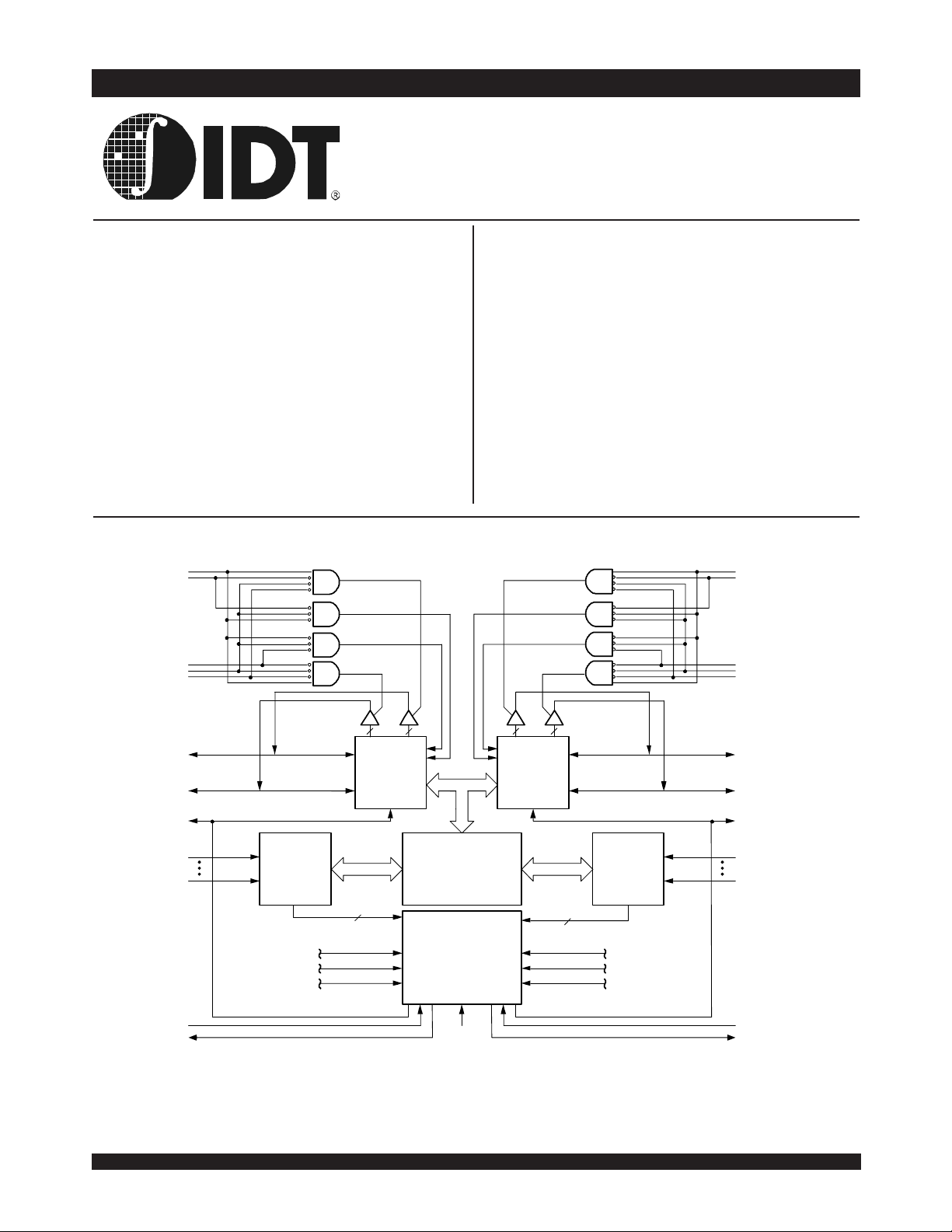
Functional Block Diagram
R/W
L
UB
L
ADVANCED
IDT70P35/34L
IDT70P25/24L
select when cascading more than one device
◆◆
◆
◆◆
M/S = VIH for BUSY output flag on Master
M/S = VIL for BUSY input on Slave
◆◆
◆
◆◆
BUSY and Interrupt Flag
◆◆
◆
◆◆
On-chip port arbitration logic
◆◆
◆
◆◆
Full on-chip hardware support of semaphore signaling
between ports
◆◆
◆
◆◆
Fully asynchronous operation from either port
◆◆
◆
◆◆
LVTTL-compatible, single 1.8V (±100mV) power supply
◆◆
◆
◆◆
Available in a 100-pin Thin Quad Flatpack (TQFP) package,
100-pin 0.8mm pitch Ball Grid Array (fpBGA), and 100-pin
0.5mm pitch BGA (fpBGA)
◆◆
◆
◆◆
Industrial temperature range (-40°C to +85°C) is available
for selected speeds
R
R/W
UB
R
LB
L
CE
L
OE
L
I/O9L-I/O
I/O0L-I/O
17L
BUSY
A
12L
A
SEM
INT
(5)
(4)
8L
(2,3)
L
(1)
0L
L
(3)
L
Address
Decoder
CE
OE
R/W
13
L
L
L
NOTES:
12 is a NC for IDT70P34 and IDT70P24.
1. A
2. (MASTER): BUSY is output; (SLAVE): BUSY is input.
3. BUSY outputs and INT outputs are non-tri-stated push-pull.
0x - I/O7x for IDT70P25/24.
4. I/O
8x - I/O15x for IDT70P25/24.
5. I/O
©2004 Integrated Device Technology, Inc.
I/O
Control
MEMORY
ARRAY
ARBITRATION
INTERRUPT
SEMAPHORE
LOGIC
M/S
1
I/O
Control
LB
R
CE
R
OE
R
,
I/O9R-I/O
I/O0R-I/O
BUSY
A
Address
Decoder
13
CE
R
OE
R
R/W
R
12R
A
0R
SEM
INT
5683 drw 01
(5)
17R
(4)
8R
(2,3)
R
(1)
R
(3)
R
FEBRUARY 2004
DSC-5683/2
IDT70P35/34L(IDT70P25/24L) ADVANCED
High-Speed 1.8V 8/4K x 18 (8/4K x 16) Dual-Port Static RAM Industrial and Commercial Temperature Ranges
Description
The IDT70P35/34L (IDT70P25/24L) is a high-speed 8/4K x 18
(8/4K x 16) Dual-Port Static RAM. The IDT70P35/34L (IDT70P25/24L)
is designed to be used as a stand-alone Dual-Port RAM or as a
combination MASTER/SLAVE Dual-Port RAM for 36-bit (32-bit) or wider
memory system applications results in full-speed, error-free operation
without the need for additional discrete logic.
This device provides two independent ports with separate control,
address, and I/O pins that permit independent, asynchronous access for
reads or writes to any location in memory. An automatic power down
feature controlled by CE permits the on-chip circuitry of each port to enter
a very low standby power mode.
Fabricated using IDT’s CMOS high-performance technology, these
devices typically operate on only 30.6mW of power.
The IDT70P35/34L (IDT70P25/24L) is packaged in a plastic 100-pin
Thin Quad Flatpack, a 100-pin fine pitch Ball Grid Array, and a 100-pin
0.5mm pitch fpBGA.
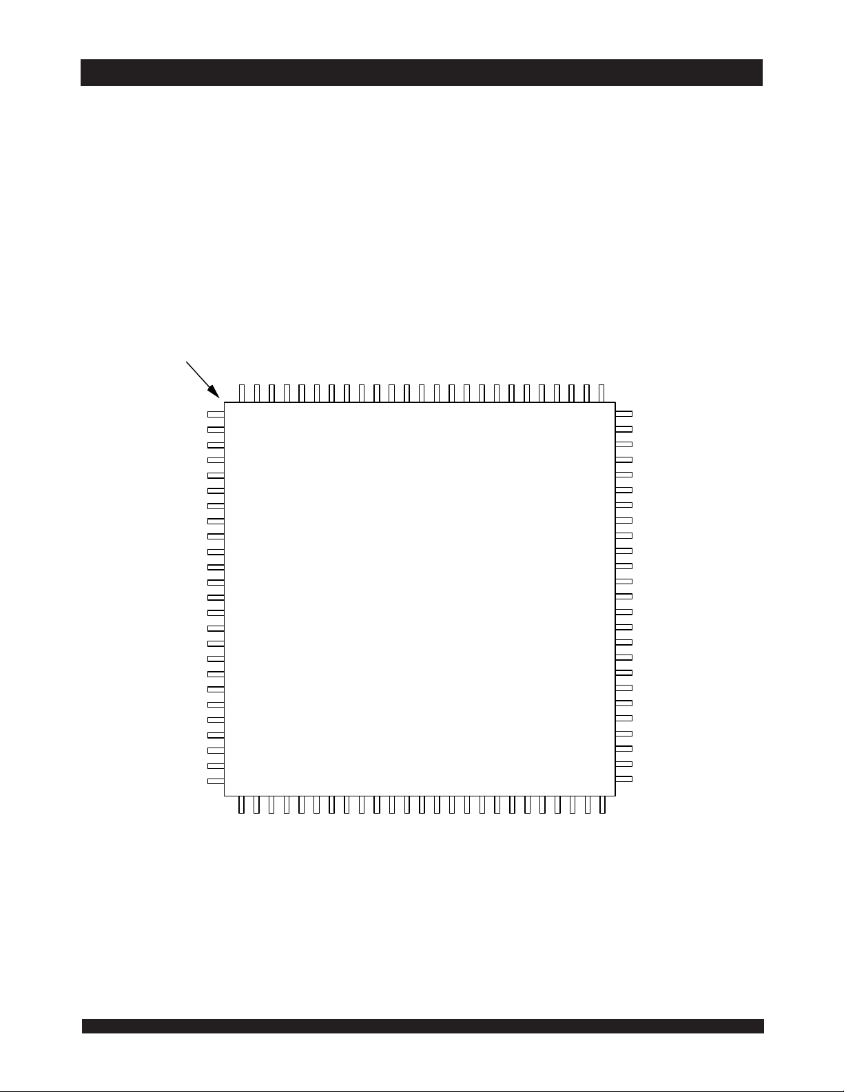
IDT70P35/34 Pin Configurations
12/17/03
Index
N/C
N/C
I/O
8L
I/O
17L
I/O
11L
I/O
12L
I/O
13L
I/O
14L
Vss
I/O
15L
I/O
16L
V
DD
Vss
0R
I/O
I/O
1R
I/O
2R
V
DD
I/O
3R
I/O
4R
I/O
5R
I/O
6R
I/O
8R
I/O
17R
N/C
N/C
L
0
L
L
L
L
L
L
1
9
7
6
O
O
/
/
I
I
100 99 98 97 96 95 94 93 92 91 90 89 88 87 86 85 84 83 82 81 80 79 78 77 76
1
2
3
4
5
6
7
8
9
10
11
12
13
14
15
16
17
18
19
20
21
22
23
24
25
26 27 28 29 30 31 32 33 34 35 3637 38 39 40 41 42 43 44 45 46 47 48 49 50
R
R
7
9
O
O
/
/
I
I
5
O
O
O
/
/
/
I
I
I
R
R
R
1
2
0
1
1
1
O
O
O
/
/
/
I
I
I
L
4
3
2
s
O
/
I
R
3
1
O
/
I
s
O
O
/
/
I
I
V
s
R
R
4
5
s
1
1
V
O
O
/
/
I
I
(1,2,3,4)
L
L
1
0
O
O
/
/
I
I
L
L
D
W
E
/
D
O
R
V
IDT70P35/34PF
PN100-1
(5)
100-Pin TQFP
R
W
/
R
(6)
s
R
s
M
V
E
S
Top View
R
R
6
E
1
O
O
/
I
)
L
M
E
S
1
(
L
L
L
E
C
L
L
L
1
0
2
1
B
B
A
L
U
L
L
L
1
1
9
A
A
A
L
8
7
6
A
A
A
N/C
75
74
N/C
73
N/C
72
N/C
71
70
69
68
67
66
65
64
63
62
61
60
59
58
57
56
55
54
53
52
51
5L
A
A
4L
A
3L
A
2L
A
1L
A
0L
INT
L
BUSY
Vss
M/S
BUSY
INT
R
A
0R
A
1R
A
2R
A
3R
A
4R
N/C
N/C
N/C
N/C
L
R
,
)
R
R
R
R
1
R
R
R
(
1
B
B
E
L
U
C
0
R
1
1
2
A
A
1
A
R
9
8
7
A
A
A
R
6
A
5683 drw 02
R
5
A
NOTES:
12 is a NC for IDT70P34.
1. A
DD pins must be connected to power supply.
2. All V
SS pins must be connected to ground.
3. All V
4. PN100-1 package body is approximately 14mm x 14mm x 1.4mm.
5. This package code is used to reference the package diagram.
6. This text does not indicate orientation of the actual part marking.
6.42
2

IDT70P35/34L (IDT70T25/24L) ADVANCED
High-Speed 1.8V 8/4K x 18 (8/4K x 16) Dual-Port Static RAM Industrial and Commercial Temperature Ranges
IDT70P35/34 Pin Configurations(cont'd)
IDT70P35/34BF
BF100
100-Pin fpBGA
A5
R
V
B5
SEM
C5
UB
D5
A
E5 E6
V
Top View
A6
SS
V
SS
B6
R
R/W
C6
I/O
D6
LB
V
16R
SS
R
11R
SS
12/16/03
9R
4R
A3
(1)
A
12R
B3
A
C3
A
D3D2
A
R
R
B4
8R
C4
5R
D4
2R
0R
A2A1
A
6R
A
B1
B2
NC NC
C1
D1
A
E1 E2 E3 E4
M/S A
C2
3R
A
INT
A
1R
BUSY
A4
CE
A
10R
A
7R
NC
A
1L
(1,2,3,4)
(5)
(6)
SS
15R
14R
4R
A8
I/O
I/O
R
C8
I/O
D8
I/O
I/O
A7
V
B7
R
OE
C7
I/O
D7
I/O
R
E7 E8 E9 E10
I/O
13R
12R
11R
17R
2R
A9
I/O
B9
I/O
C9
I/O
D9
I/O
I/O
10R
9R
8R
5R
0R
A10
I/O
B10B8
I/O
C10
I/O
D10
I/O
V
7R
6R
3R
1R
DD
F1 F2 F3
V
SS
BUSY
L
G1 G2
INT
L
H1 H2 H3 H4
A
2L
J1 J2 J3 J4
A
4L
A
K1 K2 K3
A
7L
A
NOTES:
1. A
12 is a NC for IDT70P34.
2. All VDD pins must be connected to power supply.
SS pins must be connected to ground.
3. All V
4. BF-100 package body is approximately 10mm x 10mm x 1.4mm with 0.8mm ball pitch.
5. This package code is used to reference the package diagram.
6. This text does not indicate orientation of the actual part marking.
G3
A
3L
A
5L
8L
A
A
9L
A
A
A
11L
12L
0L
6L
10L
(1)
F4
G4
SEM
K4
UB
F5
NC
G5 G6 G7 G8 G10
NC
H5 H6
LB
CE
L
J5
L
R/W
K5 K6 K7 K8 K9 K10
V
L
F6 F8 F9 F10
V
DD
V
SS
V
SS
I/O
3L
I/O
L
L
DD
1L
J6 J7 J8
OE
L
V
DD
F7
V
DD
I/O
14L
I/O
15L
I/O
G9
V
2L
J9
V
I/O
SS
,
17L
SS
5L
5683 drw 03
I/O
I/O
J10
I/O
I/O
NC I/O
H7 H8 H9 H10
I/O
7L
I/O4LI/O
I/O
0L
12L
I/O8LI/O
6L
I/O
16L
13L
11L
10L
9L
6.42
3

IDT70P35/34L(IDT70P25/24L) ADVANCED
High-Speed 1.8V 8/4K x 18 (8/4K x 16) Dual-Port Static RAM Industrial and Commercial Temperature Ranges
IDT70P25/24 Pin Configurations
12/17/03
Index
N/C
N/C
N/C
N/C
10L
I/O
I/O
11L
I/O
12L
I/O
13L
V
I/O
14L
I/O
15L
V
V
I/O
I/O
I/O
V
I/O
I/O
I/O
I/O
N/C
N/C
N/C
N/C
SS
DD
SS
0R
1R
2R
DD
3R
4R
5R
6R
L
L
L
L
L
L
L
9
8
7
6
O
O
/
/
I
I
100999897969594939291908988878685848382818079787776
1
2
3
4
5
6
7
8
9
10
11
12
13
14
15
16
17
18
19
20
21
22
23
24
25
26 27 28 29 30 31 32 33 34 35 36 37 38 39 40 41 42 43 44 45 46 47 48 49 50
R
R
7
8
O
O
/
/
I
I
5
O
O
O
/
/
/
I
I
I
R
R
R
9
0
1
1
1
O
/
O
O
I
/
/
I
I
L
4
3
2
O
O
O
/
/
/
I
I
I
R
R
R
2
3
4
1
1
1
O
O
O
/
/
/
I
I
I
(1,2,3,4)
L
L
L
1
0
S
S
O
/
I
V
D
E
D
O
/
I
O
V
IDT70P25/24PF
PN100-1
100-Pin TQFP
Top View
S
R
S
5
1
V
O
/
I
S
R
R
S
E
W
V
/
O
R
(5)
(6)
L
W
/
R
R
M
E
S
)
L
M
E
S
R
E
C
1
(
L
L
L
E
C
R
B
U
L
L
L
1
0
2
1
B
B
A
U
L
)
R
R
1
(
1
B
1
R
L
2
A
1
A
L
L
L
1
1
9
A
A
A
R
R
R
0
9
8
1
A
A
A
L
8
7
6
A
A
A
N/C
75
N/C
74
N/C
73
N/C
72
71
70
69
68
67
66
65
64
63
62
61
60
59
58
57
56
55
54
53
52
51
R
R
7
6
A
A
5683 drw 04
R
5
A
5L
A
A
4L
A
3L
A
2L
A
1L
A
0L
INT
L
BUSY
V
SS
M/S
BUSY
INT
R
A
0R
A
1R
A
2R
A
3R
A
4R
N/C
N/C
N/C
N/C
L
R
.
NOTES:
12 is a NC for IDT70P24.
1. A
DD pins must be connected to power supply.
2. All V
SS pins must be connected to ground.
3. All V
4. PN100-1 package body is approximately 14mm x 14mm x 1.4mm.
5. This package code is used to reference the package diagram.
6. This text does not indicate orientation of the actual part marking.
6.42
4

IDT70P35/34L (IDT70T25/24L) ADVANCED
High-Speed 1.8V 8/4K x 18 (8/4K x 16) Dual-Port Static RAM Industrial and Commercial Temperature Ranges
IDT70P25/24 Pin Configurations(cont'd)
IDT70P25/24BF
(5)
A6
V
SS
B6
R
R/W
C6
R
I/O
D6
LB
V
SS
12/16/03
A2A1
A
6R
B1
A
B2
NC NC A
C1
A
D1
A
E1 E2 E3 E4
M/S
3R
1R
C2
A
D2
INT
BUSY
9R
4R
A3
(1)
A
12R
B3
8R
C3
A
5R
D3
A
2R
R
R
A
0R
A4
B4
C4
D4
100-Pin fpBGA
Top View
A5
CE
R
V
B5
A
10R
SEM
C5
A
7R
UB
D5
NC
A
A
E5 E6 E7 E8 E9 E10
1L
V
BF100
SS
11R
SS
(1,2,3,4)
(6)
R
15R
R
A7
V
B7
OE
C7
I/O
D7
I/O
I/O
SS
14R
13R
4R
NC
12R
11R
10R
2R
A9
I/O
B9
I/O
C9
D9
I/O
I/O
NC
9R
8R
5R
0R
A10
I/O
B10
I/O
C10
I/O
D10
I/O
V
7R
6R
3R
1R
DD
A8
I/O
B8
I/O
R
C8
I/O
D8
I/O
F1 F2 F3 F4
V
SS
BUSY
G1 G2
INT
L
A
H1
A
J1 J2 J3 J4
A
K1 K2 K3 K4
NOTES:
12 is a NC for IDT70P24.
1. A
2. All VDD pins must be connected to power supply.
SS pins must be connected to ground.
3. All V
4. BF-100 package body is approximately 10mm x 10mm x 1.4mm with 0.8mm ball pitch.
5. This package code is used to reference the package diagram.
6. This text does not indicate orientation of the actual part marking.
H2
2L
A
5L
4L
A
7L
A
A
A
L
G3
A
3L
H3 H4
A
10L
8L
A
11L
9LA12L
0L
6L
(1)
G4
LB
SEM
UB
F5 F6 F8 F9 F10
V
DD
V
NC
G5 G6 G7
V
H5 H6
CE
J5
L
R/W
K5
V
L
SS
DD
NC
L
SS
I/O
3L
L
I/O
1L
J6 J7 J8 J9 J10
L
OE
L
K6
V
DD
F7
H7
K7
V
NC
I/O
I/O
I/O
DD
I/O
13L
G8 G9 G10
I/O
11LVSS
H8 H9 H10
7L
NC NC
4L
I/O
6L
K8
0L
I/O
2L
I/O
14L
I/O
I/O
I/O
V
SS
I/O
K9 K10
I/O
5L
I/O
5683 drw 05
15L
12L
,
10L
9L
8L
6.42
5

IDT70P35/34L(IDT70P25/24L) ADVANCED
High-Speed 1.8V 8/4K x 18 (8/4K x 16) Dual-Port Static RAM Industrial and Commercial Temperature Ranges
IDT70P25/24 Pin Configurations
100-Ball 0.5mm Pitch BGA
12/17/03
8R
4R
1R
A3
A
11R
B3
A
7R
C3
A
2R
D3
BUSY
NC
A4
UB
R
B4
A
9R
C4
6R
D4
INT
INT
R
L
R
A2A1
A
5R
A
3R
0R
B2
A
C2
A
D2
B1
A
C1
A
D1
NCNC I/O
E1 E2 E3 E4
Vss Vss
M/S
(1,2,3,4)
70P25/24BY
BY-100
Top View
A5
Vss VssSEMRI/O
B5
CE
C5
LB
D5
A
10R
E5 E6 E7 E8 E9 E10
(5)
(6)
15R
R
14R
13R
4R
A8
I/O
B8
V
C8
I/O
D8
V
R
(1)
A7
B7
OE
C7
I/O
D7
I/O
I/O
A6
B6
R
R/W
C6
R
NC
D6
A
12R
Vss
12R
DD
11R
8R
DD
A9
I/O
B9
I/O
C9
I/O
D9
I/O
I/O
10R
9R
7R
5R
1R
A10
B10
I/O
C10
D10
I/O
Vss
6R
VssA
2R
A
12L
NC
UB
F5 F6
1L
G5
(1)
H5 H6
L
L
V
DD
OE
CE
J5
V
DD
K5
SEM
G6
L
L
J6 J7 J8 J9
K6
L
F1 F2 F3
NC
2L
A
4L
A
7L
A
8L
BUSY
G3
H3 H4
K3
A
Vss
G1
H1 H2
J1
K1
NOTES:
12X is a NC for IDT70P24.
1. A
DD pins must be connected to power supply.
2. All V
SS pins must be connected to ground supply.
3. All V
4. BY100-1 package body is approximately 6mm x 6mm x 1mm, ball pitch 0.5mm.
5. This package code is used to reference the package diagram.
6. This text does not indicate orientation of the actual part-marking.
G2
NC
A
A
A
A
0L
J2 J3 J4
3L
K2
6L
A
A
A
5L
9L
10L
11L
F4
L
G4
A
LB
K4
F7
Vss
I/O
G7
I/O3LI/O
H7 H8 H9 H10
I/O
1L
Vss
R/W
I/O
K7
L
V
I/O
3R
11L
DD
4L
0L
F8
I/O
G8 G9
I/O
F9 F10
I/O
0R
12L
I/O
NC NC
I/O
6L
K8
I/O
2L
K9
I/O
15LVDD
14L
I/O
8L
5L
5683 drw 06
G10
I/O
I/O
J10
I/O
K10
I/O
13L
10L
9L
7L
6.42
6
IDT70P35/34L (IDT70T25/24L) ADVANCED
High-Speed 1.8V 8/4K x 18 (8/4K x 16) Dual-Port Static RAM Industrial and Commercial Temperature Ranges
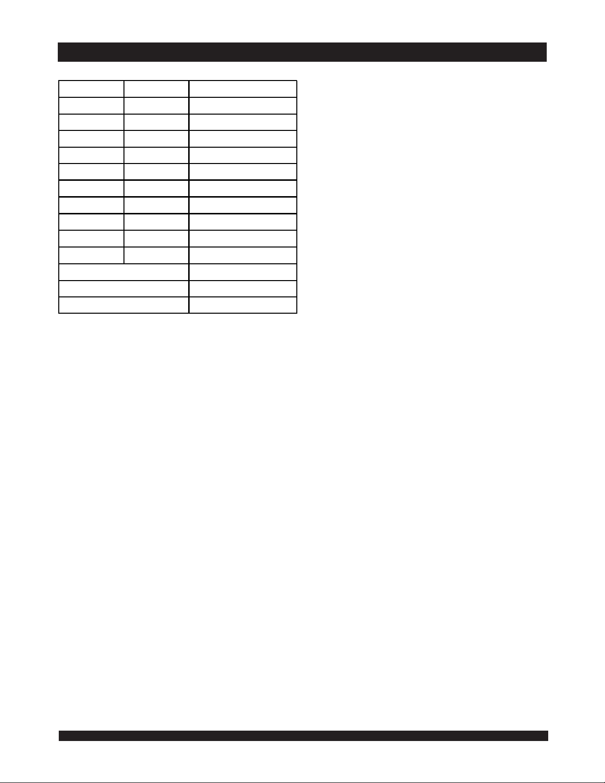
Pin Names
Left Port Right Port Names
CE
L
R/W
L
OE
0L
- A
A
0L
I/O
SEM
UB
L
LB
L
INT
BUSY
L
- I/O
L
L
(2)
Chip Enable
Read /Write Enable
Output Enable
Address
Data Input/Output
Semaphore Enable
Upper Byte Select
Lowe r Byte S elec t
Inte rrup t Flag
Busy Flag
Power (1.8V)
Ground (0V)
(3)
(4)
NOTE:
12 is a NC for IDT70P34 and IDT70P24.
1. A
0x - I/O15x for IDT70P25/24.
5683 tbl 01
2. I/O
3. IDT70P35/34L: UBx controls I/O
IDT70P25/24L: UBx controls I/O
4. IDT70P35/34L: LBx controls I/O
IDT70P25/24L: LBx controls I/O
9x - I/O17x
8x - I/O15x
0x - I/O8x
0x - I/O7x
CE
R
R/W
R
OE
R
(1)
12L
17L
A0R - A
(2)
I/O0R - I/O
SEM
UB
LB
INT
L
BUSY
(1)
12R
17R
R
R
R
R
R
M/S Master or Slave Select
DD
V
SS
V
6.42
7