


IDEAL INDUSTRIES, INC.
TECHNICAL MANUAL
MODEL: 61-320
MODEL: 61-322
MODEL: 61-324
The Service Information provides the following information:
•Precautions and safety information
•Specifications
•Performance test procedure
•Calibration and calibration adjustment procedure
•Basic maintenance (cleaning, replacing the battery and fuses)
Form Number: TM61320-2-4
Revision: 2. Date: Sep 2002
Form number TM61320-2-4 |
Rev 2 September 2002 |

TABLE OF CONTENTS |
Page # |
|
|
Introduction |
1 |
Precautions and Safety Information |
1 |
Symbols |
1 |
|
|
Safety |
2 |
|
|
Specifications |
3 |
|
|
General Specification |
3 |
|
|
Voltage Specifications |
4 |
|
|
Current Specifications |
5 |
|
|
Resistance, Diode, Continuity Specifications |
5 |
|
|
Capacitance, Frequency Specifications |
6 |
|
|
Physical and environment characteristics |
7 |
|
|
Certification and compliance |
7 |
|
|
Required Equipment |
8 |
|
|
Basic Maintenance |
9 |
|
|
Opening the Meter Case |
9 |
|
|
Replacing the Battery |
9 |
|
|
Testing Fuses |
10 |
|
|
Replacing Fuses |
10 |
|
|
Cleaning |
10 |
|
|
Performance Tests |
11 |
|
|
Testing the Display |
11 |
|
|
Testing the Voltage Function |
11/12 |
|
|
Testing the Resistance Function |
12 |
|
|
Testing the Capacitance Function |
13 |
|
|
Testing the Diode |
13 |
|
|
Testing the Milliamp (mA) Function |
13 |
|
|
Testing the microamp Function |
14 |
|
|
Testing the Frequency Function |
14/15 |
|
|
Calibration |
15 |
|
|
Calibrating DCV, ACV Functions |
15 |
|
|
Calibration Adjustment Points |
16 |
|
|
Form number TM61320-2-4 |
Rev 2 September 2002 |
Page 1
Introduction
 Warning
To avoid shock or injury, do not perform the verification tests or calibration procedures described in this manual unless you are qualified to do so.
The information provided in this document is for the use of qualified personnel only.
 Caution
The 61-320, 61-322, and 61-324 contain parts that can be damaged by static discharge. Follow the standard practices for handling static sensitive devices.
For additional information about IDEAL INDUSTRIES, INC. and its products, and services, visit IDEAL INDUSTRIES, INC. web site at: www.idealindustries.com
Precautions and Safety Information
Use the meter only as described in the Users Manual. If you do not do so, the protection provided by the meter may be impaired. Read the “Safety Information” page before servicing this product. In this manual, a Warning identifies conditions and actions that pose hazard(s) to the user; a Caution identifies conditions and actions that may damage the meter or the test instruments.
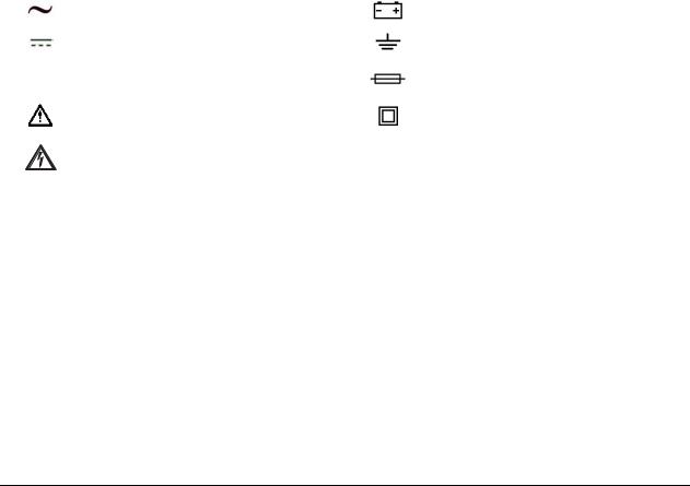
The Symbols
The symbols used on the meter and in this manual are explained in Table A.
Table A. The Symbols
Symbol |
Meaning |
Symbol |
Meaning |
|
|
|
|
|
Alternating signal |
|
Battery |
|
|
|
|
|
Direct signal |
|
Earth ground |
|
|
|
|
CAT III |
IEC over voltage Category III |
|
Fuse |
|
|
|
|
|
Refer to the manual. Important information. |
|
Double insulated |
|
|
|
|
|
Take appropriate precautions. Hazardous |
|
|
|
voltage may be present |
|
|
Form number TM61320-2-4 |
Rev 2 September 2002 |

Page 2
SAFETY
Review the following safety precautions to avoid injury and prevent damage to this product or any products connected to it. To avoid potential hazards, use the product only as specified.
 CAUTION. These statements identify conditions or practices that could result in damage to the equipment or other property.
 WARNING. These statements identify conditions or practices that could result in personal injury or loss of life.
Specific precautions
Use proper Fuse. To avoid fire hazard, use only the fuse type and rating specified for this product.
Do not operate without covers. To avoid personal injury, do not apply any voltage or current to the product without the covers in place.
Electric overload. Never apply a voltage to a connector on the product that is outside the range specified for that connector.
Avoid electric shock. To avoid injury or loss of life, do not connect or disconnect probes or test leads while they are connected to a voltage source.
Do not operate in wet/damp conditions. To avoid electric shock, do not operate this product in wet or damp conditions.
Form number TM61320-2-4 |
Rev 2 September 2002 |
Page 3
SPECIFICATIONS
All specifications are warranted unless noted typical and apply to the 61-320, 61-322 and 61-324.
Stated accuracies are at 23ºC ± 5ºC at less than 80% relative humidity and without the battery indicator displayed.
General specifications
Characteristics |
Description |
|
|
|
|
|
|
Display count |
6,000 |
|
|
|
|
|
|
Numeric update rate |
1.5 times / sec |
|
|
|
|
|
|
Polarity display |
Automatic |
|
|
|
|
|
|
Overrange display |
“OL” is displayed |
|
|
|
|
|
|
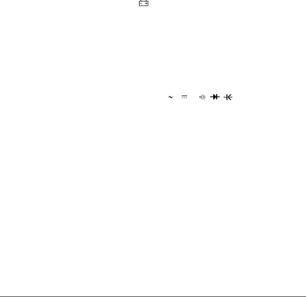
Low voltage indicator |
is indicated |
|
|
Automatic power-off time |
Automatic backlight off = 10 minutes |
||
|
|
||
Power source |
1.5 x 2 IEC LR03 or AAA size for 61-320 |
||
One 9V dry cell battery for 61-322 and 61-324 |
|||
|
|||
|
|
||
Maximum input voltage |
1000V CAT III between V and COM |
||
|
|
||
Maximum floating voltage |
1000V CAT III between any terminal and earth ground |
||
|
|
||
Maximum input current |
600mA between mA and COM |
||
|
|
|
|
Maximum open circuit Voltage (current inputs) |
600V between mA and COM |
|
|
|
|
|
|
Overload protection mA connector |
1A (600V) fast blow fuse |
|
|
|
|
|
|
V connector |
1100 Vp V , V , Ω, , |
, , Hz, µA |
|
|
|
||
Temperature Coefficient |
0.15 x (Spec. Accuracy) / ºC, <18ºC or >28ºC |
||
|
|
|
|
Battery Life |
300 hours typical (alkaline) |
|
|
|
|
|
|
Form number TM61320-2-4 |
Rev 2 September 2002 |

Page 4
Measurement Characteristics
Accuracy is ± (% reading + number of digits) at 23°C ± 5°C, less than 80% R.H.
DC Volts
Range |
Resolution |
Accuracy |
Over voltage |
|
protection |
||||
|
|
|
||
600.0mV |
100µV |
|
|
|
|
|
|
|
|
6.000V |
1mV |
|
|
|
|
|
±(0.5% + 2dgt) |
1000V rms |
|
60.00V |
10mV |
|||
|
|
|
|
|
600.0V |
100mV |
|
|
|
|
|
|
|
|
1000V |
1V |
|
|
|
|
|
|
|
|
AC Volts |
|
|
|
|
Range |
Resolution |
Accuracy |
Over voltage |
|
protection |
||||
|
|
|
||
600.0mV |
100µV |
Unspecified |
|
|
|
|
|
|
|
6.000V |
1mV |
|
|
|
|
|
±(0.9% + 5dgt) |
1000V rms |
|
60.00V |
10mV |
|||
|
|
50Hz ~ 500Hz |
|
|
600.0V |
100mV |
|
||
* |
|
|||
750V |
1V |
|
|
|
|
|
|
|
Input Impedance: 10MΩ // less than 100pF.
CMRR / NMRR: (Common Mode Rejection Ratio) (Normal Mode Rejection Ratio)
VAC: CMRR > 60dB at DC, 50Hz / 60Hz
VDC: CMRR > 100dB at DC, 50Hz / 60Hz NMRR > 50dB at DC, 50Hz / 60Hz
AC Conversion Type: 61-320: Average sensing rms indication.
61-322 / 61-324: AC conversions are ac-coupled, true rms responding, calibrated to the sine wave input.
*The basic accuracy is specified for sine wave below 4000 counts. Over 4000 counts, need to add 0.6% to the accuracy for non-sine waves below 2000 counts, refer to the following for accuracy:
Crest Factor (C.F.):
+1.5% addition error for C.F. from 1.4 to 3
+3.0% addition error for C.F. from 3 to 4 where C.F.=Peak / RMS
Form number TM61320-2-4 |
Rev 2 September 2002 |
 Loading...