


ICP C4A318GKA100, C4A318GKD100, C4A324GKD100, C4A330GKA100, C4A330GKD100 Installation Guide
...INSTALLATION INSTRUCTIONS R- 410A Split System Air Conditioner
C4A3, H4A3, T4A3,
CXA6, HXA6, TXA6
These instructions must be read and understood completely before attempting installation.
IMPORTANT: Effective January 1, 2015, all split system and packaged air conditioners must be installed pursuant to applicable regional efficiency standards issued by the Department of Energy.
SAFETY CONSIDERATIONS
Improper installation, adjustment, alteration, service, maintenance, or use can cause explosion, fire, electrical shock, or other conditions which may cause death, personal injury, or property damage. Consult a qualified installer, service agency, or your distributor or branch for information or assistance. The qualified installer or agency must use factoryauthorized kits or accessories when modifying this product. Refer to the individual instructions packaged with the kits or accessories when installing.
Follow all safety codes. Wear safety glasses, protective clothing, and work gloves. Use quenching cloth for brazing operations. Have fire extinguisher available. Read these instructions thoroughly and follow all warnings or cautions included in literature and attached to the unit. Consult local building codes and current editions of the National Electrical Code (NEC) NFPA 70. In Canada, refer to current editions of the Canadian electrical code CSA 22.1.
Recognize safety information. This is the safetyalert
symbol !! When you see this symbol on the unit and in instructions or manuals, be alert to the potential for personal injury. Understand these signal words; DANGER, WARNING, and CAUTION. These words are used with the safetyalert symbol. DANGER identifies the most serious hazards which will result in severe personal injury or death. WARNING signifies hazards which could result in personal injury or death. CAUTION is used to identify unsafe practices which would result in minor personal injury or product and property damage. NOTE is used to highlight suggestions which will result in enhanced installation, reliability, or operation.
!WARNING
ELECTRICAL SHOCK HAZARD
Failure to follow this warning could result in personal injury or death.
Before installing, modifying, or servicing system, main electrical disconnect switch must be in the OFF position. There may be more than 1 disconnect switch. Lock out and tag switch with a suitable warning label.
!WARNING
EXPLOSION HAZARD
Failure to follow this warning could result in death, serious personal injury, and/or property damage.
Never use air or gases containing oxygen for leak testing or operating refrigerant compressors. Pressurized mixtures of air or gases containing oxygen can lead to an explosion.
INSPECT NEW UNIT
After uncrating the unit, inspect it thoroughly for any obvious or hidden damage. If damage is found, notify the transportation company immediately and file a concealed damage claim.
!CAUTION
PROPERTY DAMAGE HAZARD
Failure to follow this caution may result in property damage
R- 410A systems operate at higher pressures than R- 22 systems. When working with R- 410A systems, use only service equipment and replacement components specifically rated or approved for R- 410A service.
!CAUTION
CUT HAZARD
Failure to follow this caution may result in personal injury.
Sheet metal parts may have sharp edges or burrs. Use care and wear appropriate protective clothing and gloves when handling parts.
LOCATION
Check local codes for regulations concerning zoning, noise, platforms, and other issues.
Locate unit away from fresh air intakes, vents, or bedroom windows. Noise may carry into the openings and disturb people inside.
421 01 5103 05 9/22/17
INSTALLATION INSTRUCTIONS
Locate unit in a well drained area, or support unit high enough so that water runoff will not enter the unit.
Locate unit away from areas where heat, lint, or exhaust fumes will be discharged onto unit (as from dryer vents).
Locate unit away from recessed or confined areas where recirculation of discharge air may occur (refer to CLEARANCES section of this document).
Rooftop installation is acceptable providing the roof will support the unit and provisions are made for water drainage and noise/vibration dampening.
NOTE: Roof mounted units exposed to wind may require wind baffles. Consult the manufacturer for additional information.
CLEARANCES
When installing, allow sufficient space for airflow clearance, wiring, refrigerant piping, and service. Allow 24 in. (610 mm) clearance to service end of unit and 48 in. (1219.2 mm) above unit. For proper airflow, a 6 in. (152.4 mm) clearance on one side of unit and 12 in. (304.8 mm) on all remaining sides must be maintained. Maintain a distance of 24 in. (609.6 mm) between units or 18 in. (457.2 mm) if no overhang within 12 ft. (3.66 m). Position so water, snow, or ice from roof or eaves cannot fall directly on unit.
Operating Ambient
The minimum outdoor operating ambient in cooling mode without accessory is 55_F (12.78_C). The maximum outdoor operating ambient in cooling mode is 125_F (51.7_C) for non13 SEER models and 115_F (46.11_C) for 13 SEER models.
UNIT SUPPORT
NOTE: Unit must be level + 2 degrees [a ⅜inch rise or fall per foot of run (10 mm rise or fall per 305 mm of run)] or compressor may not function properly.
A. GROUND LEVEL INSTALLATION
The unit must be level and supported above grade by beams, platform, or a pad. Platform or pad can be of open or solid construction but should be of permanent materials such as concrete, bricks, blocks, steel, or pressuretreated timbers approved for ground contact. Soil conditions must be considered so that the platform
R- 410A Split System Air Conditioner
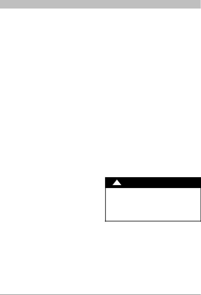
or pad does not shift or settle and leave the unit partially supported. Minimum pad dimensions are shown in Figure 1.
If beams or an open platform are used for support, it is recommended that the soil be treated or area be graveled to reduce the growth of grasses and weeds.
To minimize vibration or noise transmission, it is recommended that supports not be in contact with the building structure. However, slabs on grade constructions with an extended pad are normally acceptable.
B. ROOF TOP INSTALLATION
This type of installation is not recommended on wood frame structures where low noise levels are required.
Supporting structure or platform for the unit must be level. If installation is on a flat roof, locate unit minimum 6 inches (152 mm) above roof level.
Place the unit over one or more load bearing walls. If there are several units, mount them on platforms that are selfsupporting and span several load bearing walls. These suggestions are to minimize noise and vibration transmission through the structure. If the structure is a home or apartment, avoid locating the unit over bedrooms or study.
NOTE: When unit is to be installed on a bonded guaranteed roof, a release must be obtained from the building owner to free the installer from all liabilities.
C. FASTENING UNIT DOWN
If conditions or local codes require the unit be attached in place, remove the knockouts in the base pan and install tie down bolts through the holes (refer to Figure 1).
Contact local distributor for hurricane holddown details and the P.E. (Professional Engineer) certification, when required.
!CAUTION
PROPERTY DAMAGE HAZARD
Failure to follow this caution may result in property damage.
Inadequate unit support may cause excessive vibration, noise, and/or stress on the refrigerant lines, leading to refrigerant line failure.
2 |
421 01 5103 05 |
INSTALLATION INSTRUCTIONS
Figure 1 |
|
|
|
|
|
|
Tie Down Knockouts |
|
|||||||||||
|
|
|
|
|
|
|
|
|
|
|
|
|
|
|
|
|
|
|
|
|
|
|
|
|
|
|
|
|
|
|
|
|
|
|
|
|
|
|
|
a” (10mm) dia. Tie Down Knockouts |
|
|
View From Top |
|
|||||||||||||||
|
|
|
|
|
|||||||||||||||
In Base Pan (2 places) |
|
|
|
|
|
|
|
|
|
|
|
|
|
||||||
|
|
|
|
|
|
|
|
|
|
|
|
|
|
|
|
|
|
|
|
|
|
|
|
|
|
|
|
|
|
|
|
|
|
|
|
|
|
|
|
|
|
|
|
|
|
|
|
|
|
|
|
|
|
|
|
|
|
|
|
|
|
|
|
|
|
|
|
|
|
|
|
|
|
|
|
|
|
|
|
|
|
|
|
|
|
|
|
|
|
|
|
|
|
|
|
|
|
|
|
|
|
|
|
|
|
|
|
|
|
|
|
|
|
|
|
|
|
|
|
|
|
|
|
|
|
|
|
|
|
|
|
|
|
|
|
|
|
|
|
Base |
Pan |
Depth |
C |
B |
A |
Base Pan Width |
Inches (mm)
Base Pan |
|
Tie Down |
Minimum |
||
Width x |
Knockouts |
Mounting Pad |
|||
Depth |
A |
|
B |
C |
Dimensions |
|
|
|
|
|
|
23 x 23 |
7- 3/4 |
|
4- 7/16 |
18 |
23 x 23 |
(584 x 584) |
(197) |
|
(113) |
(457) |
(584 x 584) |
|
|
|
|
|
|
2511/16 x |
9- 1/16 |
|
4- 7/16 |
21- 1/4 |
26 x 26 |
2511/16 |
|
||||
(230) |
|
(113) |
(540) |
(660 x 660) |
|
(652 x 652) |
|
||||
|
|
|
|
|
|
|
|
|
|
|
|
31- 1/8 x |
9- 1/16 |
|
6- 1/2 |
24- 5/8 |
31- 1/2 x |
31- 1/8 |
|
31- 1/2 |
|||
(230) |
|
(165) |
(625) |
||
(791 x 791) |
|
(800 x 800) |
|||
|
|
|
|
||
|
|
|
|
|
|
3415/16 x |
9- 1/16 |
|
6- 1/2 |
28- 7/16 |
35 x 35 |
3415/16 |
|
||||
(230) |
|
(165) |
(722) |
(889 x 889) |
|
(887 x 887) |
|
||||
|
|
|
|
|
|
REFRIGERATION SYSTEM
A. COMPONENT MATCHES
Check to see that the proper system components are in place, especially the indoor coil.
R- 410A outdoor units can only be used with R- 410A specific indoor coils. If there is a refrigerant mismatch, consult the indoor coil manufacturer to determine if a refrigerant conversion kit is available for the indoor coil.
This outdoor unit is designed for use only with indoor coils that utilize a TXV refrigerant metering device or Piston with Teflon ring metering device. If any other type of metering device is installed on the indoor coil, consult the indoor coil manufacturer to determine if a TXV conversion kit is available.
Installing with TXV
When installing a TXV on an indoor coil, follow the instructions provided with the new TXV.
A typical TXV installation is shown in Figure 2.
R- 410A Split System Air Conditioner
Figure 2 |
Typical TXV Installation |
|
|
INDOOR
COIL
EQUALIZER
TUBE
SENSING |
SUCTION |
BULB |
TUBE |
 LIQUID
TUBE
TXV
10 O’clock
2 O’clock
SENSING BULB


 STRAP
STRAP
 SUCTION TUBE 3/4 IN. OD & SMALLER
Installing with Indoor Piston - cooling operation.
Check piston size shipped with indoor unit to see if it matches required indoor piston size. If it does not match, replace indoor piston with the correct piston size.
NOTE: Correct pistons are shipped with select outdoor units in the accessory bag and are only for use in certain qualified and approved fancoils, i.e. FEM4P. (See Product Specifications for list of approved fancoils that use accessory piston.)
The piston included with the FMA4P* and FM(C,U)4P* fancoils are unique to those products and cannot be replaced with the piston shipped with the outdoor unit. Refer to the AHRI Directory to check if your combination can use a piston or requires an accessory TXV.
See Figure 3.
When changing indoor piston, use a backup wrench. Hand tighten hex nut, then tighten with wrench 1/2 turn. Do not exceed 30 ftlbs.The indoor piston contains a Teflon ring (or seal) which is used to seat against the inside of distributor body, and must be installed properly to ensure proper seating in the direction for cooling operation.
421 01 5103 05 |
Specifications subject to change without notice. |
3 |
|
|
INSTALLATION INSTRUCTIONS
Figure 3 |
Indoor (cooling) Piston |
|
BRASS |
|
DISTRIBUTOR |
HEX NUT |
TEFLON SEAL |
|
|
TEFLON RING |
|
|
PISTON |
|
|
FLOW IN |
|
|
COOLING |
|
|
PISTON |
BRASS |
|
HEX BODY |
|
|
RETAINER |
|
|
|
|
|
STRAINER |
|
|
|
L10S017 |
B. REFRIGERANT LINE SETS
The refrigerant line set must be properly sized to assure maximum efficiency and proper oil circulation.
Refer to Product Specifications and Long Line Applications Guideline for line set sizing.
NOTE: Total line set length must not exceed 200 feet (61 m).
A crankcase heater must be used when the refrigerant line length exceeds 80 feet (24.4 m).
If outdoor unit is more than 10 feet (3 m) higher than the indoor coil, refer to the Long Line Applications Guideline for instructions.
When the outdoor unit is higher than the indoor coil, the vertical separation must not exceed 100 feet (30 m).
When the outdoor unit is lower than the indoor coil, the vertical separation must not exceed 50 feet (15.2 m).
If it is necessary to add refrigerant line in the field, use dehydrated or dry, sealed, deoxidized, copper refrigeration tubing. Do not use copper water pipe.
Do not remove rubber plugs or caps from copper tubing until connections are ready to be made.
R- 410A Split System Air Conditioner
Be extra careful when bending refrigeration tubing. Tubing can “kink” easily, and if this occurs, the entire length of tubing must be replaced.
!WARNING
PERSONAL INJURY HAZARD
Failure to relieve system pressure could result in personal injury and/or death.
Relieve pressure and recover all refrigerant before servicing existing equipment, and before final unit disposal. Use all service ports and open all flowcontrol devices, including solenoid valves.
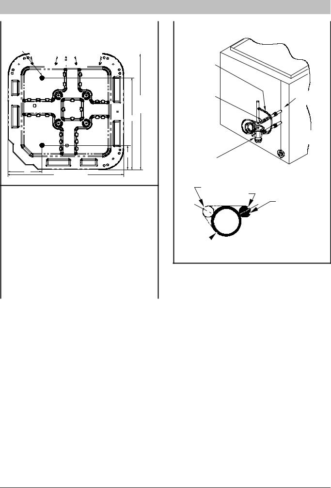
C.ROUTING AND SUSPENDING REFRIGERANT LINES
Run refrigerant lines as straight and direct as possible, avoiding unnecessary bends and turns. Always insulate the entire suction line. Both lines should be insulated when routed through an attic or when routed through an underground raceway.
When routing refrigerant lines through a foundation or wall, do not allow refrigerant lines to come in direct contact with the building structure. Make openings large enough so that lines can be wrapped with extra insulation. Fill all gaps with RTV caulk. This will prevent noise transmission between the tubing and the foundation or wall.
Along floor or ceiling joists, suspend refrigerant lines so that they do not contact the building structure, water pipes, or ductwork. Use insulated or suspension type hangers. Metal straps must be at least 1” (25 mm) wide to avoid cutting into the tube insulation. Keep the liquid and suction lines separate. Refer to Figure 4.
!CAUTION
UNIT OPERATION HAZARD
Failure to follow this caution may result in improper product operation.
Do not leave system open to atmosphere any longer than absolutely required for installation. Internal system components - especially refrigerant oils - are extremely susceptible to moisture contamination. Keep ends of tubing sealed during installation until the last possible moment.
4 |
421 01 5103 05 |

INSTALLATION INSTRUCTIONS |
|
R- 410A Split System Air Conditioner |
||
Figure 4 |
|
Routing and Suspending Refrigerant Lines |
|
|
OUTDOOR WALL |
INDOOR WALL |
|
|
JOIST |
|
HANGER STRAP |
|
||
|
|
|
|
|
CAULK |
|
|
(AROUND SUCTION |
INSULATION |
|
LIQUID TUBE |
TUBE ONLY) |
||
|
|
|||
|
|
SUCTION TUBE |
||
|
|
|
|
|
SUCTION TUBE |
|
INSULATION |
|
1” (25mm) |
|
MIN |
LIQUID TUBE |
THROUGH THE WALL |
SUSPENSION |
!CAUTION
UNIT OPERATION HAZARD
Failure to follow this caution may result in improper product operation.
Do not bury more than 36” (1m) of line set underground. Refrigerant may migrate to cooler buried section during extended periods of unit shutdown, causing refrigerant slugging and possible compressor damage at startup.
If ANY section of the line set is buried underground, provide a minimum 6” (152mm) vertical rise at the service valve.
D. OUTDOOR UNIT HIGHER THAN INDOOR UNIT
Proper oil return to the compressor should be maintained with suction gas velocity. If velocities drop below 1500 fpm (feet per minute), oil return will be decreased. To maintain suction gas velocity, do not upsize vertical suction risers.
E. LIQUID LINE FILTERDRIER
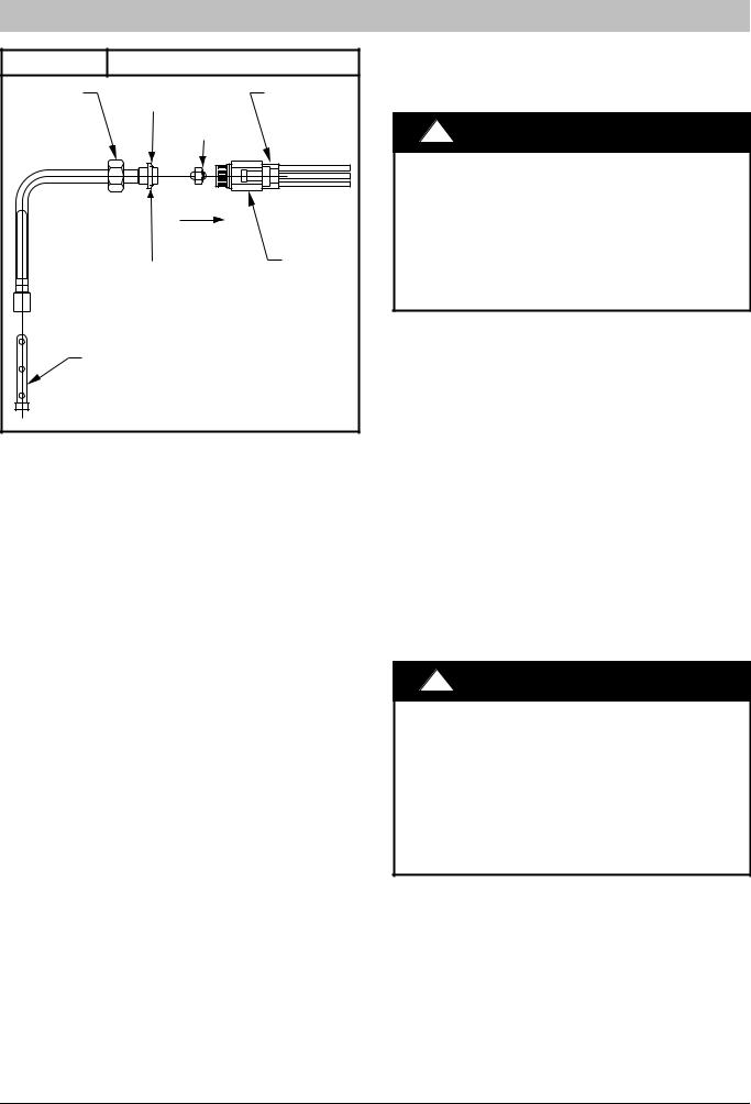
Outdoor units are shipped with an appropriate filterdrier for installation in the liquid line. Leave the plugs in the tube ends until the filterdrier is installed. The optimal location for the filterdrier is close to the indoor coil. Install the filterdrier with the arrow pointing towards the indoor coil. Refer to Figure 5.
|
Figure 5 |
|
|
|
|
|
Liquid Line FilterDrier |
|||||||||||||||||||||||
|
|
|
|
|
|
Installed at Indoor Coil |
||||||||||||||||||||||||
|
|
|
|
|
|
|
|
|
|
|
|
|
|
|
|
|
|
|
|
|
|
|
|
|
|
|
||||
|
|
|
|
|
|
|
|
|
|
|
|
|
|
|
|
|
|
|
|
|
|
|
|
|
|
|
|
|
|
|
|
|
|
|
|
|
|
|
|
|
|
|
|
|
|
|
|
|
|
|
|
|
|
|
|
|
|
|
|
|
|
|
|
|
|
|
|
|
|
|
|
|
|
|
|
|
|
|
|
|
|
|
|
|
|
|
|
|
|
|
|
|
|
|
|
|
|
|
|
|
|
|
|
|
|
|
|
|
|
|
|
|
|
|
|
|
|
|
|
|
|
|
|
|
|
|
|
|
|
|
|
|
|
|
|
|
|
|
|
|
|
|
|
|
|
|
|
|
|
|
|
|
|
|
|
|
|
|
|
|
|
|
|
|
|
|
|
|
|
|
|
|
|
|
|
|
|
|
|
|
|
|
|
|
|
|
|
|
|
|
|
|
|
|
|
|
|
|
|
|
|
|
|
|
|
|
|
|
|
|
|
|
|
|
|
|
|
|
|
|
|
|
|
|
|
|
|
|
|
|
|
|
|
|
|
|
|
|
|
|
|
|
|
|
|
|
|
|
|
|
|
|
|
|
|
|
|
|
|
|
|
|
|
|
|
|
|
|
|
|
|
|
|
|
|
|
|
|
|
|
|
|
|
|
|
|
|
|
|
|
|
|
|
|
|
|
|
|
|
|
|
|
|
|
|
|
|
|
|
|
|
|
|
|
|
|
|
|
|
|
|
|
|
|
|
|
|
|
|
|
|
|
|
|
|
|
|
|
|
|
|
|
|
|
|
|
|
|
|
|
|
|
|
|
|
|
|
|
|
|
|
|
|
|
|
|
|
|
|
|
|
|
|
|
|
|
|
|
|
|
|
|
|
|
|
|
|
|
|
|
|
|
|
|
|
|
|
|
|
|
|
|
|
|
|
|
|
|
|
|
|
|
|
|
|
|
|
|
|
|
|
|
|
|
|
|
|
|
|
|
|
|
|
|
|
|
|
|
|
|
|
|
|
|
|
|
|
|
|
|
|
|
|
|
|
|
|
|
|
|
|
|
|
|
|
|
|
|
|
|
|
|
|
|
|
|
|
|
|
|
|
|
|
|
|
|
|
|
|
|
|
|
|
|
|
|
|
|
|
|
|
|
|
|
|
|
|
|
|
|
|
|
|
|
|
|
|
|
|
|
|
|
|
|
|
|
|
|
|
|
|
|
|
|
|
|
|
|
|
|
|
|
|
|
|
|
|
|
|
|
|
|
|
|
|
|
|
|
|
|
|
|
|
|
|
|
|
|
|
|
|
|
|
|
|
|
|
|
|
|
|
|
|
|
|
|
|
|
|
|
|
|
|
|
|
|
|
|
|
|
|
|
|
|
|
|
|
|
|
|
|
|
|
|
|
|
|
|
|
|
|
|
|
|
|
|
|
|
|
|
|
|
|
|
|
|
|
|
|
|
|
|
|
|
|
|
|
|
|
|
|
|
|
|
|
|
|
|
|
|
|
|
|
|
|
|
|
|
|
|
|
|
|
|
|
|
|
|
|
|
|
|
|
|
|
|
|
|
|
|
|
|
|
|
|
|
|
|
|
|
|
|
|
|
|
|
|
|
|
|
|
|
|
|
|
|
|
|
|
|
|
|
|
|
|
|
|
|
|
|
|
|
|
|
|
|
|
|
|
|
|
|
|
FilterDrier |
|
(arrow points towards indoor coil) |
3811- 84 |
F. SERVICE VALVES
Service valves are closed and tube stubs are plugged from the factory. Outdoor units are shipped with a refrigerant charge sealed in the unit. Leave the service valves closed until all other refrigerant system work is complete or the charge will be lost. Leave the plugs in place until line set tubing is ready to be inserted.
Service valve bodies are brass and tube stubs are copper.
421 01 5103 05 |
Specifications subject to change without notice. |
5 |
|
|
INSTALLATION INSTRUCTIONS |
R- 410A Split System Air Conditioner |
|
|
Figure 6 |
Service Valve |
|
SERVICE VALVE |
VALVE CORE |
|
G. BRAZING CONNECTIONS
NOTE: Remove valve core from schrader port on both Service Valves BEFORE brazing. This helps prevent overheating and damage to valve seals (refer to Figure 6). Replace valve core when brazing is completed.
!WARNING
FIRE HAZARD
Failure to remove refrigerant and oil charge before brazing could result in personal injury, death, and/or property damage.
Refrigerant and oil mixture could ignite and burn as it escapes and contacts brazing torch. Make sure the refrigerant charge is properly removed from both the high and low sides of the system before brazing any component or lines.
Clean line set tube ends with emery cloth or steel brush. Remove any grit or debris.
Insert line set tube ends into service valve tube stubs.
Apply heat absorbing paste or heat sink product between service valve and joint. Wrap service valves with a heat sinking material such as a wet cloth.
Braze joints using a SilFos or Phoscopper alloy.
!CAUTION
PRODUCT DAMAGE HAZARD
Failure to follow this caution may result in product damage.
Braze with SilFos or Phoscopper alloy on copper- tocopper joints and wrap a wet cloth around rear of fitting to prevent damage to TXV.
H. EVACUATING LINE SET AND INDOOR COIL
The unit is shipped with a factory refrigerant charge. The liquid line and suction line service valves have been closed after final testing at the factory. Do not disturb these valves until the line set and indoor coil have been evacuated and leak checked, or the charge in the unit may be lost.
NOTE: Do not use any portion of the factory charge for purging or leak testing. The factory charge is for filling the system only after a complete evacuation and leak check has been performed.
!CAUTION
PRODUCT DAMAGE HAZARD
Failure to follow this caution may result in product damage.
Never use the outdoor unit compressor as a vacuum pump. Doing so may damage the compressor.
Line set and indoor coil should be evacuated using the recommended deep vacuum method of 500 microns. If deep vacuum equipment is not available, the alternate triple evacuation method may be used by following the specified procedure.
If vacuum must be interrupted during the evacuation procedure, always break vacuum with dry nitrogen.
Deep Vacuum Method
The deep vacuum method requires a vacuum pump capable of pulling a vacuum to 500 microns and a vacuum gauge capable of accurately measuring this vacuum level. The deep vacuum method is the most positive way of assuring a system is free of air and water.
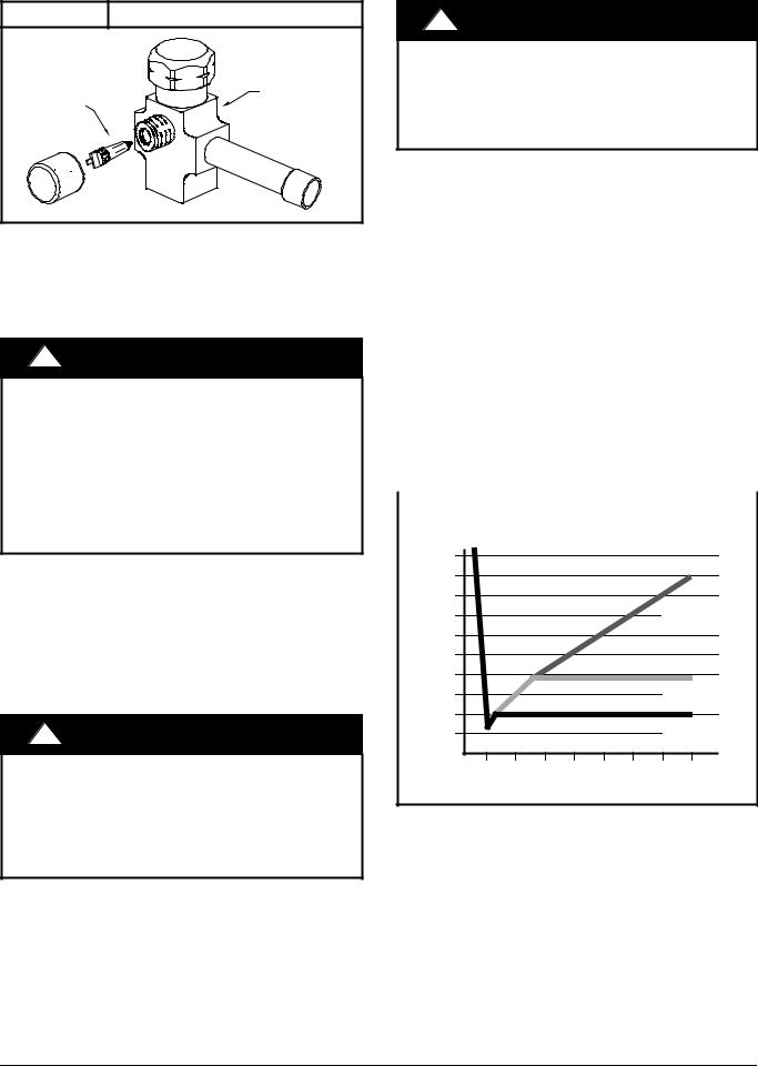
Watch the vacuum gauge as the system is pulling down. The response of the gauge is an indicator of the condition of the system (refer to Figure 7).
With no leaks in the system, allow the vacuum pump to run for 30 minutes minimum at the deep vacuum level.
Figure 7 |
Deep Vacuum Gauge Response |
|
and System Conditions |
||
|
||
|
|
5000 |
|
|
|
|
|
|
|
4500 |
|
|
|
|
|
|
|
4000 |
|
|
|
|
|
LEAK IN |
|
3500 |
|
|
|
|
|
||
|
|
|
|
|
SYSTEM |
||
3000 |
|
|
|
|
|
||
|
|
|
|
|
|
|
|
2500 |
|
|
|
|
|
|
|
MICRONS 2000 |
|
|
|
|
|
|
|
1500 |
|
|
|
|
|
VACUUM TIGHT |
|
|
|
|
|
|
TOO WET |
||
1000 |
|
|
|
|
|
||
|
|
|
|
|
TIGHT |
||
500 |
|
|
|
|
|
||
|
|
|
|
|
DRY SYSTEM |
||
|
|
|
|
|
|
||
0 |
1 |
2 |
3 |
4 |
5 |
6 |
7 |
|
|
|
MINUTES |
|
|
|
|
Triple Evacuation Method
The triple evacuation method should only be used when system does not contain any water in liquid form and vacuum pump is only capable of pulling down to 28 inches of mercury (711mm Hg). Refer to Figure 8 and proceed as follows:
1.Pull system down to 28 inches of mercury (711mm Hg) and allow pump to continue operating for an additional 15 minutes.
2.Close manifold valves or valve at vacuum pump and shut off vacuum pump.
3.Connect a nitrogen cylinder and regulator to system and fill with nitrogen until system pressure is 2 psig.
6 |
421 01 5103 05 |
INSTALLATION INSTRUCTIONS
4.Close nitrogen valve and allow system to stand for 1 hour. During this time, dry nitrogen will diffuse throughout the system absorbing moisture.
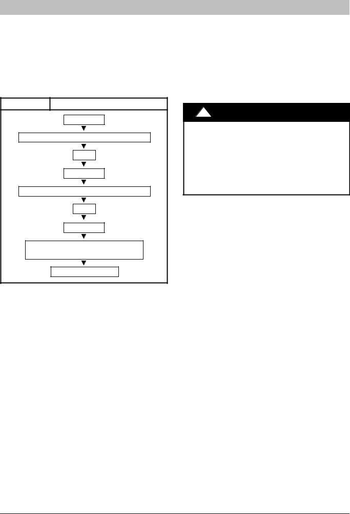
5.Repeat this procedure as indicated in Figure 8.
6.After the final evacuate sequence, confirm there are no leaks in the system. If a leak is found, repeat the entire process after repair is made.
Figure 8 Triple Evacuation Sequence
EVACUATE
BREAK VACUUM WITH DRY NITROGEN
WAIT
EVACUATE
BREAK VACUUM WITH DRY NITROGEN
WAIT
EVACUATE
CHECK FOR TIGHT, DRY SYSTEM (IF IT HOLDS DEEP VACUUM)
CHARGE SYSTEM
I. OPENING SERVICE VALVES
Outdoor units are shipped with a refrigerant charge sealed in the unit. Opening the service valves releases this charge into the system.
NOTE: Open the Suction service valve first. If the Liquid service valve is opened first, oil from the compressor may be drawn into the indoor coil TXV, restricting refrigerant flow and affecting operation of the system.
Remove Suction service valve cap and insert a hex wrench into the valve stem. Hold the valve body steady with an endwrench and back out the stem by turning the hex wrench counterclockwise. Turn the stem until it just contacts the rolled lip of the valve body.
After the refrigerant charge has bled into the system, open the Liquid service valve.
NOTE: These are not backseating valves. It is not necessary to force the stem tightly against the rolled lip.
The service valve cap is a primary seal for the valve and must be properly tightened to prevent leaks. Make sure cap is clean and apply refrigerant oil to threads and sealing surface on inside of cap.
Tighten cap finger tight and then tighten additional 6 of a turn (1 wrench flat) to properly seat the sealing surfaces.
R- 410A Split System Air Conditioner
J. GAUGE PORTS
Check for leaks at the schrader ports and tighten valve cores if necessary. Install plastic caps finger tight.
ELECTRICAL WIRING
(*XA6 all sizes; *4A3 sizes 18, 3660 only)
NOTE: *4A3 sizes 24 and 30 on page 14.
!WARNING
ELECTRICAL SHOCK HAZARD
Failure to turn off the main (remote) electrical disconnect device could result in personal injury or death.
Before installing, modifying or servicing system, turn OFF the main (remote) electrical disconnect device. There may be more than one disconnect device.
The supply voltage must be 208/230 volts (197 volt minimum to 253 volts maximum) 60 Hz single phase.
Outdoor units are approved for use with copper conductors only. Do not use aluminum wire.
Refer to unit rating plate for minimum circuit ampacity and circuit protection requirements.
Grounding
Permanently ground unit in accordance with the National Electrical Code and local codes or ordinances. Use a copper conductor of the correct size from the grounding lug in control box to a grounded connection in the service panel or a properly driven and electrically grounded ground rod.
Wiring Connections
Make all outdoor electrical supply (Line Voltage) connections with raintight conduit and fittings. Most codes require a disconnect switch outdoors within sight of the unit. Consult local codes for special requirements.
Route electrical supply (Line Voltage) wiring through knockout hole in bottom of Control Box. Connect wires to Contactor and Ground Lug according to Wiring Diagram on unit. Refer to Figure 9.
Route thermostat wiring through rubber grommet in bottom of Control Box. Low voltage lead wires are provided in the control box for connection to thermostat wires (use wire nuts). Refer to Wiring Diagram on unit and Figure 10 for low voltage wiring examples.
NOTE: Use No. 18 AWG (American Wire Gage) colorcoded, insulated (35 ° C minimum) wire. If thermostat is located more than 100 feet (31 m) from unit as measured along the control voltage wires, use No. 16 AWG colorcoded wires to avoid excessive voltage drop.
NOTE: Some models are factory equipped with Comfort Alertt Diagnostics device. If Comfort Alert is used as a field installed option, then a hot bundle must be run for proper connection.
421 01 5103 05 |
Specifications subject to change without notice. |
7 |
|
|
 Loading...