


Icp TDS-725I, TDSM-712, TDS735I, TDS-734I, TDS-734 User Manual
...tDS-700 Series
User Manual
Tiny Serial-to-Ethernet Device Server |
Aug. 2018, Ver. 2.2 |
WARRANTY
All products manufactured by ICP DAS are warranted against defective materials for a period of one year from the date of delivery to the original purchaser.
WARNING
ICP DAS assumes no liability for damages consequent to the use of this product. ICP DAS reserves the right to change this manual at any time without notice. The information furnished by ICP DAS is believed to be accurate and reliable. However, no responsibility is assumed by ICP DAS for its use, nor for any infringements of patents or other rights of third parties resulting from its use.
COPYRIGHT
Copyright © 2018 by ICP DAS. All rights are reserved.
TRADEMARKS
Names are used for identification purposes only and may be registered trademarks of their respective companies.
CONTACT US
If you have any questions, please feel free to contact us via email at:
service@icpdas.com, service.icpdas@gmail.com
SUPPORT
This manual relates to the following modules: tDS-712, tDS-722, tDS-732
tDS-715, tDS-725, tDS735 tDS-718, tDS-724, tDS-734 tDS-712i, tDS-722i, tDS-732i tDS-715i, tDS-725i, tDS735i tDS-718i, tDS-724i, tDS-734i tDSM-712, tDS-718i-D

Tiny Serial-to-Ethernet Device Server
TABLE OF CONTENTS
PACKING LIST............................................................................................................................................................. |
|
|
5 |
||||
MORE INFORMATION................................................................................................................................................ |
|
|
5 |
||||
1. |
INTRODUCTION ................................................................................................................................................ |
|
|
6 |
|||
|
1.1 |
|
ETHERNET SOLUTIONS ......................................................................................................................................... |
|
9 |
||
|
1.2 |
|
VXCOMM TECHNOLOGY.......................................................................................................................................... |
|
8 |
||
|
|
|
11 |
||||
|
1.3 |
|
WEB SERVER TECHNOLOGY |
|
|
||
2. |
HARDWARE INFORMATION .......................................................................................................................... |
|
12 |
||||
|
2.1 |
|
SPECIFICATIONS.......................................................................................................................................................... |
|
|
13 |
|
|
2.2 |
|
FEATURES ..................................................................................................................................................... |
|
|
14 |
|
|
2.3PoE |
|
A |
................................................................................................................................................. |
|
|
12 |
|
|
andPPEARANCEEthernet RJ-45 Jack.................................................................................................................................... |
|
14 |
|||
|
+12 to +48 VDC Jack ................................................................................................................................................. |
|
|
14 |
|||
|
Operating Mode Switch ............................................................................................................................................ |
|
|
15 |
|||
|
LED Indicator ........................................................................................................................................................... |
|
|
15 |
|||
|
Serial COM Ports....................................................................................................................................................... |
|
|
16 |
|||
|
2.42.4.1 |
D |
|
|
|
|
|
|
DIN-Rail Mounting ................................................................................................................................................... |
|
|
16 |
|||
|
|
|
tDSIMENSIONS-700 Series Module..................................................................................................................................... |
|
17 |
||
|
2.5tDS- |
|
P |
A ...................................................................................................................................................... |
|
|
17 |
|
|
|
|
|
|||
|
2.4.2CA-002 Cable..................................................................................................................................................... |
|
|
19 |
|||
|
|
712/tDSIN SSIGNMENTS-712i/tDSM-712 .................................................................................................................................. |
|
20 |
|||
|
|
|
|
.............................................................................................................................................. |
|
|
20 |
|
tDS-722/tDS-722i..................................................................................................................................................... |
|
|
20 |
|||
|
tDS-732/tDS-732i..................................................................................................................................................... |
|
|
21 |
|||
|
tDS-715/tDS-715i..................................................................................................................................................... |
|
|
21 |
|||
|
tDS-725/tDS-725i..................................................................................................................................................... |
|
|
22 |
|||
|
tDS-735/tDS-735i..................................................................................................................................................... |
|
|
22 |
|||
|
tDS-718/tDS-718i..................................................................................................................................................... |
|
|
23 |
|||
|
tDS-718i-D ................................................................................................................................................................ |
|
|
23 |
|||
|
tDS-724/tDS-724i..................................................................................................................................................... |
RS-232/485/422 I |
|
24 |
|||
|
2.6RS- |
|
W |
N |
|
|
|
|
tDS-734/tDS-734i..................................................................................................................................................... |
|
NTERFACES |
24 |
|||
|
232 WiringIRING OTES..........................................................................................................................................................FOR |
|
25 |
||||
|
|
|
|
|
|
........................................................................................... |
25 |
|
RS-422 Wiring .......................................................................................................................................................... |
|
|
26 |
|||
Copyright © 2018 ICP DAS CO., Ltd. All Rights Reserved. |
-2 - |

Tiny Serial-to-Ethernet Device Server
|
RS-485 Wiring .......................................................................................................................................................... |
|
|
|
|
|
|
|
|
|
|
|
|
26 |
||||
3. |
GETTING STARTED......................................................................................................................................... |
P |
|
|
|
|
H |
|
PC |
27 |
||||||||
|
3.1 |
C |
ONNECTING THE |
|
|
|
|
|
|
|||||||||
|
3.2 |
|
|
OWER AND |
OST |
.............................................................................................................. |
27 |
|||||||||||
|
INSTALL THE VXCOMM UTILITY |
...................................................................................................................... |
|
|
30 |
|||||||||||||
|
3.3 |
CONFIGURING NETWORK SETTINGS........................................................................................................................... |
|
|
30 |
|||||||||||||
|
|
............................................................................................................. |
31 |
|||||||||||||||
|
3.4 |
C |
ONFIGURING THE |
V |
|
|
COM P |
|
|
|||||||||
|
3.5 |
C |
S |
IRTUAL |
|
|
|
ORTS |
|
|||||||||
|
ONFIGURING THE |
ERIAL |
P |
ORT |
|
|
|
|||||||||||
|
3.6 |
TESTING YOUR TDS-700 |
|
|
|
|
|
|
33 |
|||||||||
|
|
|
|
|
|
|
|
|
|
|
|
|
|
|
.......................................................................................................................... |
|
|
|
|
|
|
|
|
|
|
|
|
|
|
.................................................................................................................................... |
|
|
|
|
|
|
35 |
4. |
WEB CONFIGURATION ................................................................................................................................... |
|
|
|
|
S |
37 |
|||||||||||
|
4.1 |
L |
OGGING IN TO THE T |
DS-700 W |
|
|||||||||||||
|
4.2 |
|
|
|
|
|
EB |
|
ERVER ......................................................................................................... |
37 |
||||||||
|
HOME PAGE |
|
|
|
............................................................................................................................................ |
|
|
|
|
|
|
|
|
40 |
||||
|
4.3 |
N |
IP |
S |
|
|
|
|
|
|
|
|
|
|
|
|
39 |
|
|
|
|
|
ETWORKAddressETTING.......................................................................................................................................................Settings |
|
|
|
|
|
|
||||||||
|
4.3.1 |
|
|
|
|
|
|
|
|
40 |
||||||||
|
4.3.2 |
|
|
General Settings ......................................................................................................................................... |
|
|
|
|
|
|
43 |
|||||||
|
4.3.3 |
S |
|
Restore Factory Defaults............................................................................................................................ |
|
|
|
45 |
||||||||||
|
4.44.4.1 |
|
|
P P |
|
|
|
|
|
|
|
|
|
|
|
|
||
|
4.3.4 |
|
|
Remote Firmware Update.......................................................................................................................... |
|
|
47 |
|||||||||||
|
|
ERIALPort1ORTSettingsAGE ............................................................................................................................................. |
|
|
|
|
|
|
|
|
48 |
|||||||
|
4.54.5.1 |
F |
|
|
P |
|
|
|
............................................................................................................................................. |
|
|
|
|
|
|
|
|
48 |
|
|
|
|
|
|
|
|
|
|
|
|
|
|
|
51 |
|||
|
|
|
ILTERAccessibleAGE...................................................................................................................................................... |
|
|
|
|
|
|
|
|
|
|
|
|
|||
|
4.6 |
|
IP (filter is disabled when all zero) .......................................................................................... |
51 |
||||||||||||||
|
MONITOR PAGE |
|
|
............................................................................................................................................ |
|
|
|
|
|
|
|
|
53 |
|||||
|
4.7 |
CHANGE PASSWORD.................................................................................................................................................. |
|
|
|
|
|
|
|
|
52 |
|||||||
|
|
|
|
|
|
|
|
|
54 |
|||||||||
|
4.8 |
LOGOUT PAGE |
|
|
|
|
|
|
|
|
|
|
|
|
|
|||
5. |
TYPICAL APPLICATIONS ................................................................................................................................ |
|
|
|
|
|
|
55 |
||||||||||
|
5.1 |
VIRTUAL COM A ........................................................................................................PPLICATION |
A |
|
|
|
57 |
|||||||||||
|
5.2 |
D |
|
S |
|
C |
|
|
|
|
|
|
|
|
|
56 |
||
|
5.3 |
|
|
IRECT |
OCKET ............................................................................................................................... |
|
ONNECTION |
|
PPLICATIONS |
62 |
||||||||
|
ETHERNET I/O A ........................................................................................................................PPLICATIONS |
|
|
|
||||||||||||||
|
5.4 |
PAIR-CONNECTION ............................................................................................................................APPLICATIONS |
|
|
60 |
|||||||||||||
|
|
|
69 |
|||||||||||||||
|
5.5 |
TCP CLIENT MODE APPLICATIONS |
|
|
|
|||||||||||||
6. |
GI CONFIGURATION........................................................................................................................................ |
|
|
|
|
|
|
|
|
|
76 |
|||||||
|
6.1 |
CGI URL SYNTAX ........................................................................................................................................... |
|
|
|
|
|
|
|
|
|
|
77 |
|||||
|
6.2 |
CGI COMMAND L ...............................................................................................................................................IST |
|
|
|
|
|
|
|
76 |
||||||||
|
|
|
|
|
|
|
|
|
||||||||||
APPENDIX A: TROUBLESHOOTING ........................................................................................................................ |
|
|
|
|
79 |
|||||||||||||
|
A1. HOW DO I RESTORE THE ..............................................WEB PASSWORD FOR THE MODULE TO THE FACTORY DEFAULT PASSWORD? |
79 |
||||||||||||||||
APPENDIX B: GLOSSARY ......................................................................................................................................... |
|
|
|
|
|
|
|
|
|
|
81 |
|||||||
Copyright © 2018 ICP DAS CO., Ltd. All Rights Reserved. |
-3 - |

Tiny Serial-to-Ethernet Device Server |
|
|
1. |
ARP (ADDRESS RESOLUTION PROTOCOL) ..................................................................................................................... |
81 |
2. |
CLIENTS AND SERVERS ............................................................................................................................................... |
81 |
3. |
ETHERNET................................................................................................................................................................ |
82 |
4. |
FIRMWARE .............................................................................................................................................................. |
82 |
5. |
GATEWAY................................................................................................................................................................ |
82 |
6. |
ICMP (INTERNET CONTROL MESSAGE PROTOCOL)......................................................................................................... |
82 |
7. |
INTERNET ................................................................................................................................................................ |
82 |
8. |
IP (INTERNET PROTOCOL) ADDRESS ............................................................................................................................. |
83 |
9. |
MAC (MEDIA ACCESS CONTROL) ADDRESS .................................................................................................................. |
83 |
10. |
PACKET .............................................................................................................................................................. |
83 |
11. |
PING .................................................................................................................................................................. |
83 |
12. |
RARP (REVERSE ADDRESS RESOLUTION PROTOCOL) ................................................................................................. |
83 |
13. |
SOCKET .............................................................................................................................................................. |
84 |
14. |
SUBNET MASK..................................................................................................................................................... |
84 |
15. |
TCP (TRANSMISSION CONTROL PROTOCOL) ............................................................................................................. |
84 |
16. |
TCP/IP .............................................................................................................................................................. |
84 |
17. |
UDP (USER DATAGRAM PROTOCOL) ...................................................................................................................... |
84 |
APPENDIX C: ACTUAL BAUD RATE MEASUREMENT ............................................................................................ |
85 |
|
APPENDIX D: REVISION HISTORY.......................................................................................................................... |
86 |
|
Copyright © 2018 ICP DAS CO., Ltd. All Rights Reserved. |
-4 - |
Tiny Serial-to-Ethernet Device Server
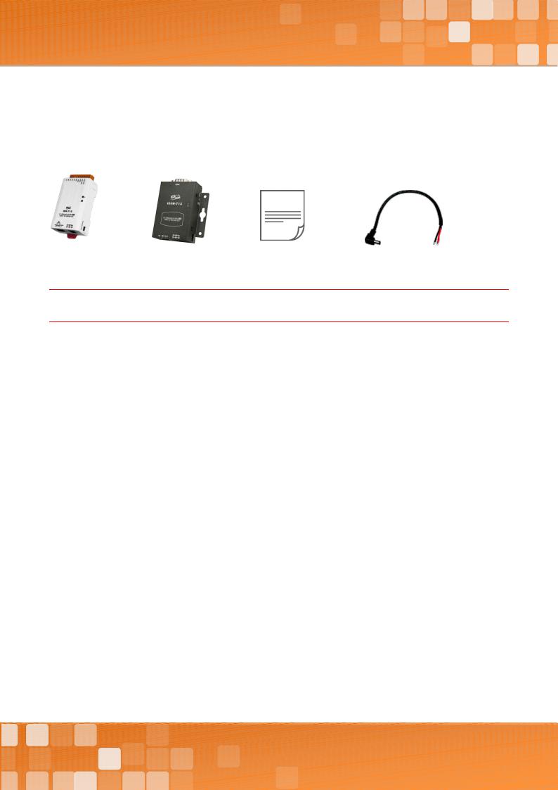
Packing List
The shipping package includes the following items:
Or
tDS-700/tDSM-700 Series |
Quick Start |
CA-002 Cable |
Note
If any of these items are missing or damaged, please contact the local distributor for more information. Save the shipping materials and cartons in case you need to ship the module in the future.
More Information
Documentation
http://ftp.icpdas.com/pub/cd/tinymodules/napdos/tds-700/document/
Firmware
http://ftp.icpdas.com/pub/cd/tinymodules/napdos/tds-700/firmware/
Software
http://ftp.icpdas.com/pub/cd/tinymodules/napdos/software/
Copyright © 2018 ICP DAS CO., Ltd. All Rights Reserved. |
-5 - |
Tiny Serial-to-Ethernet Device Server
1. Introduction
The tDS-700 is a series of Serial-to-Ethernet device servers that are designed to add Ethernet and Internet connectivity to any RS-232 and RS-422/485 device, and to eliminate the cable length limitation of legacy serial communications. By using the VxComm Driver/Utility, the built-in COM Port of the tDS-700 series can be virtualized to a standard PC COM Port in Windows. Therefore, users can transparently access or monitor serial devices over the Internet/Ethernet without the need for software modification.
tDS-700 device servers can be used to create a pair-connection application (as well as serial-bridge or serial-tunnel), and then route data between two serial devices via TCP/IP. This is useful when connecting mainframe computers, servers or other serial devices that do not themselves have Ethernet capability. By virtue of its protocol independence and flexibility, the tDS-700 meets the demands of virtually any network-enabled application.
Copyright © 2018 ICP DAS CO., Ltd. All Rights Reserved. |
-6 - |
Tiny Serial-to-Ethernet Device Server
In harsh industrial environments, the tDS-700 series (for i version) also adds 3000 VDC and +/- 4 kV ESD protection component that diverts the potentially damaging charge away from sensitive circuit to protects the module and equipment from the sudden and momentary electric current.
To achieve maximum space savings, the tDS-700 is offered in an amazingly small form-factor that enables it to be easily installed anywhere, even directly attached to a serial device or embedded into a machine. The tDS-700 features a powerful 32-bit MCU that allows it to efficiently handle network traffic. The tDS-700 offers true IEEE 802.3af-compliant (classification, Class 1) Power-over- Ethernet (PoE) functionality using a standard category 5 Ethernet cable that allows it to receive power from a PoE switch such as the NS-205PSE. If there is no PoE switch available on site, the tDS700 can accepts power input from a DC adapter.
Comparison of Device Servers:
|
Series |
PPDS |
PDS |
DS |
tDS |
tGW |
Features |
|
|||||
|
|
|
|
|
|
Virtual COM |
|
|
|
|
|
|
|
- |
|
|
|
|
|
|
|
|
|
|
|
|
|
|
|
|
|
|
Programmable |
|
|
|
|
|
- |
- |
- |
|
|
|
|
|
|
|
|
|
|
|
|
|
|
|
|
|
|
PoE |
|
|
- |
|
|
- |
|
|
|
|
|
|
|
|
|
|
|
|
|
|
|
|
|
|
|
|
Modbus Gateway |
|
|
- |
|
|
- |
- |
|
|
|
|
|
|
|
|
|
|
|
|
|
|
|
|
|
|
|
Multi-client |
|
About 20 Sockets |
|
1 Sockets/Port |
10 Sockets/Port |
|||
|
|
|
|
|
|
|
|
|
Remarks |
Professional |
|
Powerful |
|
|
Isolation for |
Cost-effective, |
Cost-effective, |
|
|
|
DS-715 |
Entry-level |
Entry-level |
|||
|
|
|
|
|
|
|||
|
|
|
|
|
|
|
|
|
Copyright © 2018 ICP DAS CO., Ltd. All Rights Reserved. |
-7 - |
Tiny Serial-to-Ethernet Device Server
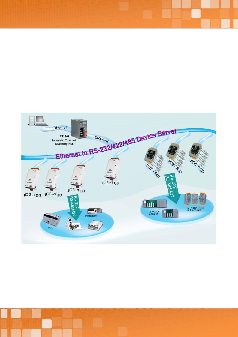
1.1 Ethernet Solutions
Nowadays, the Ethernet protocol has become the foremost standard for local area networks. Connectivity via the Internet snow common in many of the latest applications from home appliances, to vending machines, to testing equipment, to UPS, etc. An Ethernet network can link office automation and industrial control networks, access remote systems and share data and information between machines from multiple vendors, and also provides a cost-effective solution for industrial control networks.
Copyright © 2018 ICP DAS CO., Ltd. All Rights Reserved. |
-8 - |
Tiny Serial-to-Ethernet Device Server
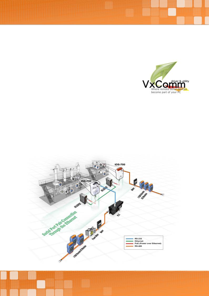
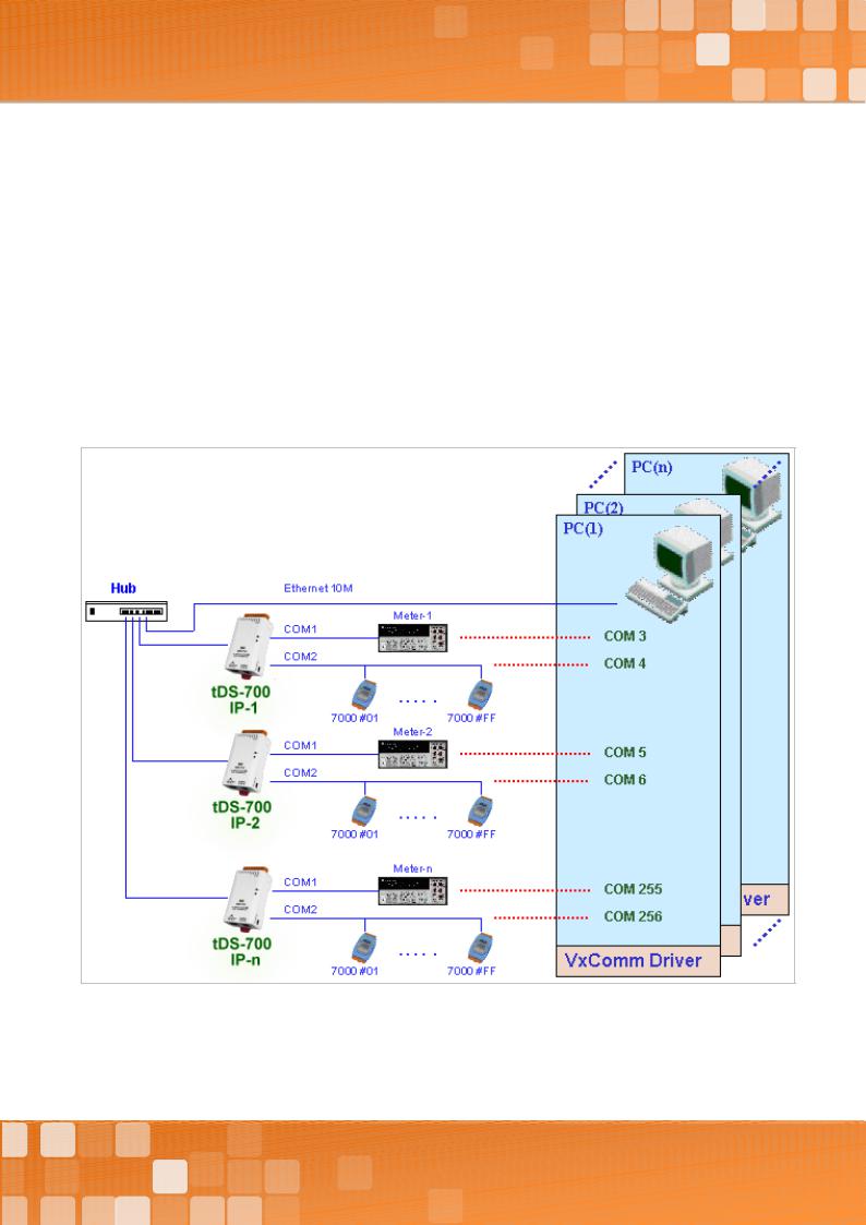
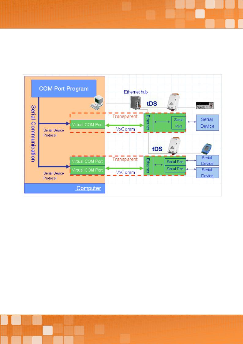
1.2 VxComm Technology
In general, writing a TCP/IP program is more difficult than writing a COM Port program. Another issue is that perhaps the existing the COM Port communication system was built many years ago and is now outdated.
As a result, a new technology, VxComm was developed to virtualize the COM Ports of the tDS-700 to allow up to 256 COM Ports to be used on a central computer. The VxComm driver saves time when accessing serial devices through the Ethernet without the need for reprogramming the COM Port software on the PC.
Copyright © 2018 ICP DAS CO., Ltd. All Rights Reserved. |
-9 - |
Tiny Serial-to-Ethernet Device Server
The VxComm driver controls all the details of the Ethernet TCP/IP programming technique, meaning that, with the assistance of tDS-700 and VxComm technology, your COM Port program will be able to access your serial devices through the Ethernet in the same way as through a COM Port.
Copyright © 2018 ICP DAS CO., Ltd. All Rights Reserved. |
-10 - |
Tiny Serial-to-Ethernet Device Server
1.3 Web Server Technology
Web server technology enables the tDS-700 to be configured via a standard web browser interface, e.g. Google Chrome, Internet Explorer, or Firefox, etc. This means that it is easy to check the configuration of thetDS-700 via an Ethernet network without needing to install any other software tools, thereby reducing the learning curve required for maintaining the device.
Copyright © 2018 ICP DAS CO., Ltd. All Rights Reserved. |
-11 - |

Tiny Serial-to-Ethernet Device Server
2. Hardware Information
This chapter provides a detailed description of the front panel, the hardware specifications, the pin assignments, the wiring notes and the dimensions for the tDS-700 series modules.
2.1 Specifications
|
Model |
|
|
|
|
|
|
tDS-712 |
|
|
tDSM- |
|
|
tDS-722 |
|
|
tDS-732 |
|
|
tDS-715 |
|
tDS-725 |
|
|
tDS-735 |
|
|
tDS-718 |
|
|
tDS-724 |
|
|
tDS-734 |
|
||
|
|
|
|
|
|
|
|
|
|
tDS-712i |
|
|
712 |
|
|
tDS-722i |
|
|
tDS-732i |
|
|
tDS-715i |
|
tDS-725i |
|
|
tDS-735i |
|
|
tDS-718i |
|
|
tDS-724i |
|
|
tDS-734i |
|
|
|
|
|
|
|
|
|
|
|
|
|
|
|
|
|
|
|
|
|
|
|
|
|
|
|
|
|
|
|
tDS-718i-D |
|
|
|
|
|
|
|
|
System |
|
|
|
|
|
|
|
|
|
|
|
|
|
|
|
|
|
|
|
|
|
|
|
|
|
|
|
|
|
|
|
|
|
|
||
|
CPU |
|
|
|
|
|
|
32-bit ARM |
|
|
|
|
|
|
|
|
|
|
|
|
|
|
|
|
|
|
|
|
|
|
|
|
|
|
|||
|
Communication Interface |
|
|
|
|
|
|
|
|
|
|
|
|
|
|
|
|
|
|
|
|
|
|
|
|
|
|
||||||||||
|
Ethernet |
|
|
10/100 Base-TX, 8-pin RJ-45 x 1, (Auto-negotiating, Auto-MDI/MDIX, LED indicator) |
|
|
|
|
|
|
|
|
|
|
|||||||||||||||||||||||
|
|
|
PoE (IEEE 802.3af, Class 1) |
|
|
|
|
|
|
|
|
|
|
|
|
|
|
|
|
|
|
|
|
|
|||||||||||||
|
|
|
|
|
|
|
|
|
|
|
|
|
|
|
|
|
|
|
|
|
|
|
|
|
|
|
|
|
|
|
|||||||
|
|
|
|
|
|
|
|
|
|
|
|
|
|
|
|
|
|
|
|
|
|
|
|
|
|
|
|
|
|
tDS-718(i): |
|
|
|
|
|
|
|
|
|
|
|
|
|
|
|
|
|
|
|
|
|
|
|
|
|
|
|
|
|
2-wire |
|
|
|
|
|
|
|
3-wire RS-232 |
|
|
|
|
|
|
|
|
|
|
|
|
|
|
|
|
|
|
|
|
|
|
|
|
|
|
3-wire |
|
|
2-wire |
|
2-wire |
|
|
|
|
|
2-wire |
|
|
2-wire |
|
|||
|
COM1 |
|
|
|
|
|
|
5-wire RS-232 |
|
|
|
|
5-wire |
|
|
|
RS-485 |
|
|
|
|
tDS-718i-D: |
|
|
|
|
|
||||||||||
|
|
|
|
|
|
|
|
|
|
|
RS-232 |
|
|
RS-232 |
|
4-wire |
|
RS-485 |
|
RS-485 |
|
|
|
|
RS-485 |
|
|
RS-485 |
|
||||||||
|
|
|
|
|
|
|
|
|
|
|
|
|
|
|
|
|
|
|
|
|
|
|
5-wire RS-232 |
|
|
|
|
|
|||||||||
|
|
|
|
|
|
|
|
|
|
|
|
|
|
|
|
|
|
|
|
|
|
RS-422 |
|
|
|
|
|
|
|
2-wire RS-485 |
|
|
|
|
|
|
|
|
|
|
|
|
|
|
|
|
|
|
|
|
|
|
|
|
|
|
|
|
|
|
|
|
|
|
|
|
|
4-wire RS-422 |
|
|
|
|
|
|
|
|
COM2 |
|
|
|
|
|
- |
|
|
|
|
|
5-wire |
|
|
3-wire |
|
|
- |
|
2-wire |
|
|
2-wire |
|
- |
|
|
5-wire |
|
|
3-wire |
|
||||
|
|
|
|
|
|
|
|
|
|
|
|
|
RS-232 |
|
|
RS-232 |
|
|
|
|
RS-485 |
|
|
RS-485 |
|
|
|
|
|
RS-232 |
|
|
RS-232 |
|
|||
|
|
|
|
|
|
|
|
|
|
|
|
|
|
|
|
|
|
|
|
|
|
|
|
|
|
|
|
|
|
|
|
||||||
|
COM3 |
|
|
|
|
|
- |
|
|
|
- |
|
|
3-wire |
|
|
- |
|
- |
|
|
2-wire |
|
- |
|
- |
|
|
3-wire |
|
|||||||
|
|
|
|
|
|
|
|
|
|
|
|
|
|
|
|
RS-232 |
|
|
|
|
|
|
|
RS-485 |
|
|
|
|
|
|
|
|
RS-232 |
|
|||
|
|
|
|
|
|
|
|
|
|
|
|
|
|
|
|
|
|
|
|
|
|
|
|
|
|
|
|
|
|
|
|
|
|
|
|||
|
Self-Tuner |
|
- |
|
|
|
|
|
|
|
|
|
|
|
Yes, automatic RS-485 direction control |
|
|
|
|
|
|
|
|||||||||||||||
|
RS- |
|
|
Bias Resistor |
|
- |
|
|
|
|
|
|
|
|
|
|
|
Yes, 1 KΩ |
|
|
|
|
|
|
|
|
|
|
|
|
|
|
|||||
|
485 |
|
|
Node |
|
|
- |
|
|
|
|
|
|
|
|
|
|
|
254 (max.) |
|
|
|
|
|
|
|
|
|
|
|
|
|
|
||||
|
UART |
|
|
|
|
|
|
16c550 or compatible |
|
|
|
|
|
|
|
|
|
|
|
|
|
|
|
|
|
|
|
|
|
|
|
|
|||||
|
Power Isolation |
|
|
1000 VDC for tDS-722i / 732i / 718i-D only |
|
|
|
|
|
|
|
|
|
|
|
|
|
|
|
|
|||||||||||||||||
|
Signal Isolation |
|
|
3000 VDC for tDS-712i / 715i / 725i / 735i / 718i / 724i / 734i only |
|
|
|
|
|
|
|
|
|
|
|
|
|
|
|||||||||||||||||||
|
ESD Protection |
|
|
+/-4 kV |
|
|
|
|
|
|
|
|
|
|
|
|
|
|
|
|
|
|
|
|
|
|
|
|
|
|
|||||||
|
COM Port Format |
|
|
|
|
|
|
|
|
|
|
|
|
|
|
|
|
|
|
|
|
|
|
|
|
|
|
|
|
|
|
||||||
|
Baud Rate |
|
|
|
|
115200 bps Max. |
|
|
|
|
|
|
|
|
|
|
|
|
|
|
|
|
|
|
|
|
|
|
|
|
|||||||
|
Data Bit |
|
|
|
|
|
5, 6, 7, 8 |
|
|
|
|
|
|
|
|
|
|
|
|
|
|
|
|
|
|
|
|
|
|
|
|
|
|
|
|||
|
Parity |
|
|
|
|
|
|
|
None, Odd, Even, Mark, Space |
|
|
|
|
|
|
|
|
|
|
|
|
|
|
|
|
|
|
|
|
|
|||||||
|
Stop Bit |
|
|
|
|
|
1, 2 |
|
|
|
|
|
|
|
|
|
|
|
|
|
|
|
|
|
|
|
|
|
|
|
|
|
|
|
|||
|
Power |
|
|
|
|
|
|
|
|
|
|
|
|
|
|
|
|
|
|
|
|
|
|
|
|
|
|
|
|
|
|
|
|
|
|
||
|
|
|
|
|
|
|
|
|
|
PoE: IEEE 802.3af, Class 1 |
|
|
|
|
|
|
|
|
|
|
|
|
|
|
|
|
|
|
|
|
|
||||||
|
Power Input |
|
|
|
|
|
|
|
|
|
|
|
|
|
|
|
|
|
|
|
|
|
|
|
|
|
|||||||||||
|
|
|
|
DC jack: +12 ~ 48 VDC |
|
|
|
|
|
|
|
|
|
|
|
|
|
|
|
|
|
|
|
|
|
|
|
|
|||||||||
|
|
|
|
|
|
|
|
|
|
|
|
|
|
|
|
|
|
|
|
|
|
|
|
|
|
|
|
|
|
|
|
|
|
||||
|
Power Consumption |
|
|
0.07 A @ 24 VDC |
|
|
|
|
|
|
|
|
|
|
|
|
|
|
|
|
|
|
|
|
|
|
|
|
|||||||||
|
Mechanism |
|
|
|
|
|
|
|
|
|
|
|
|
|
|
|
|
|
|
|
|
|
|
|
|
|
|
|
|
|
|
||||||
|
|
|
|
|
|
|
|
|
|
Male DB-9 x1 for tDS-712(i)/718i-D and tDSM-712 |
|
|
|
|
|
|
|
|
|
|
|
|
|
|
|
|
|||||||||||
|
Connector |
|
|
|
|
|
|
|
|
|
|
|
|
|
|
|
|
|
|
|
|
|
|||||||||||||||
|
|
|
|
10-Pin Removable Terminal Block x 1 for tDS-722(i)/732(i)/715(i)/725(i)/735(i)/718(i)/724(i)/734(i) |
|
|
|
|
|
|
|
||||||||||||||||||||||||||
|
|
|
|
|
|
|
|
|
|
|
|
|
|
|
|
|
|||||||||||||||||||||
|
Mounting |
|
|
|
DIN-Rail |
|
|
|
|
|
|
|
|
|
|
|
|
|
|
|
|
|
|
|
|
|
|
|
|
|
|
||||||
|
Case |
|
|
|
|
|
|
Plastic |
|
Metal |
|
|
Plastic |
|
|
|
|
|
|
|
|
|
|
|
|
|
|
|
|
|
|
|
|
|
|||
|
Environment |
|
|
|
|
|
|
|
|
|
|
|
|
|
|
|
|
|
|
|
|
|
|
|
|
|
|
|
|
|
|
||||||
|
Operating Temperature |
|
|
-25 ~ +75 °C |
|
|
|
|
|
|
|
|
|
|
|
|
|
|
|
|
|
|
|
|
|
|
|
|
|
|
|||||||
|
Storage Temperature |
|
|
-30 ~ +80 °C |
|
|
|
|
|
|
|
|
|
|
|
|
|
|
|
|
|
|
|
|
|
|
|
|
|
|
|||||||
|
Humidity |
|
|
|
10 ~ 90% RH, non-condensing |
|
|
|
|
|
|
|
|
|
|
|
|
|
|
|
|
|
|
|
|
|
|||||||||||
Note: COM1/COM2/COM3 = TCP Port 10001/10002/10003
Copyright © 2018 ICP DAS CO., Ltd. All Rights Reserved. |
-12 - |

Tiny Serial-to-Ethernet Device Server
2.2 Features
Incorporates any RS-232/422/485 serial device in Ethernet
Data transmission via Virtual COM or raw TCP connection
VxComm Driver for 32-bit and 64-bit Windows XP/7/8/2012/2016/10
Max. connections: 1 socket per serial port is suggested
Supports pair-connection (serial-bridge, serial-tunnel) applications
Supports TCP client-mode and TCP server-mode operations
Supports UDP responder for device discovery (UDP Search)
Static IP or DHCP network configuration
Easy firmware update via the Ethernet (BOOTP, TFTP)
Tiny Web server for configuration (HTTP)
Contains a 32-bit MCU that efficiently handles network traffic
10/100 Base-TX Ethernet, RJ-45 x1 (Auto-negotiating, auto MDI/MDIX, LED Indicators)
Includes redundant power inputs: PoE (IEEE 802.3af, Class 1) and DC jack
Allows automatic RS-485 direction control
Power or Signal isolation for i versions
+/- 4 kV ESD protection
Male DB-9 or terminal block connector for easy wiring
Tiny form-factor and low power consumption
RoHS compliant with no Halogen
Cost-effective device servers
Copyright © 2018 ICP DAS CO., Ltd. All Rights Reserved. |
-13 - |
Tiny Serial-to-Ethernet Device Server
2.3 Appearance
|
|
|
|
|
|
|
|
|
|
|
|
5. Serial COM Ports |
|
|
|
|
|
|
|
|
|
|
|
|
|
|
|
|
|
|
|
|
|
|
|
|
|
4. LED indicator |
|
|
|
|
|
|
|
|
|
|
|
||
|
|
|
|
|
|
|
|
|
|
|
6. DIN-Rail Mounting |
|
|
|
|
|
|
|
|
|
|
|
|||
1. PoE and Ethernet |
|
|
|
|
|
|
|
|
3. Operating Mode |
|||
|
|
|
|
|
|
|
|
|||||
|
|
|
|
|
|
|
|
Switch |
||||
RJ-45 Jack |
|
|
|
|
|
|
|
|
||||
|
|
|
|
|
|
|
|
|
|
|
|
|
|
|
2. +12 to |
|
+48 VDC Jack |
||||||||
|
|
|
||||||||||
PoE and Ethernet RJ-45 Jack
The tDS-700 series module is equipped with an RJ-45 jack that is used as the 10/100 Base-TX Ethernet port and features networking capabilities. When an Ethernet link is detected and an Ethernet packet is received, the Link/Act LED (Orange) indicator will be illuminated. When power is supplied via PoE (Power-over-Ethernet), the PoE LED (Green) indicator will be illuminated.
+12 to +48 VDC Jack
The tDS-700 series is equipped with a +12VDC to +48 VDC jack that can be used to connect a power supply. If no PoE switch is available on site, a DC adapter can be used to power the tDS-700 series module.
Copyright © 2018 ICP DAS CO., Ltd. All Rights Reserved. |
-14 - |
Tiny Serial-to-Ethernet Device Server
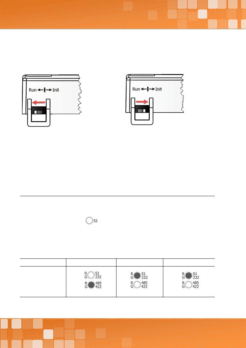
Operating Mode Switch
Run Mode: Firmware operation |
Init Mode: Configuration mode |
For tDS-700 series modules, the operating mode switch is set to the Run position by default. In order to update the firmware for the tDS-700 series module, the switch must be moved from the Run position to the Init position. The switch must be returned to the Run position after the update is complete.
LED Indicator
Once power is supplied to the tDS-700 series module, the system LED (S1) indicator will illuminate. An overview of the S1 LED functions is given below:
Function |
Color |
S1 LED Behavior |
|
|
|
Running Firmware |
|
Steady ON |
Network Ready |
Red |
Slow flashing – Once every 3 seconds |
|
|
|
Serial Port Busy |
|
Rapid flashing – Once every 0.2 seconds |
|
|
|
The following serial port LED indicators are tDS-718i-D only. You can change the serial interface via web server. An overview of the serial Port LED functions is given below:
Function |
|
RS-232 |
RS-485 |
RS-422 |
LED Behavior
Copyright © 2018 ICP DAS CO., Ltd. All Rights Reserved. |
-15 - |
Tiny Serial-to-Ethernet Device Server
Serial COM Ports
The number of serial COM Ports available depends on the type of tDS-700 series module. For more detailed information regarding the pin assignments for the Serial COM ports, refer to Section 2.5 “Pin Assignments”.
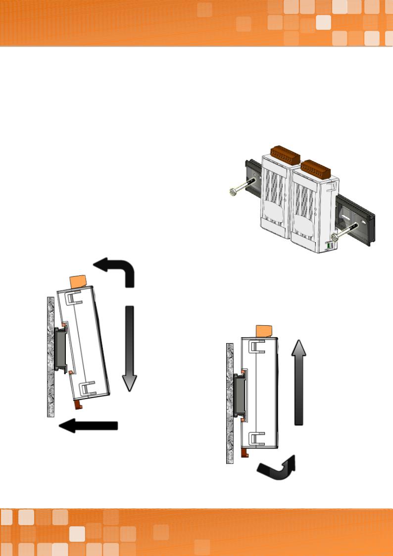
DIN-Rail Mounting
The tDS-700 series modules include simple rail clips on the bottom of the chassis that allow them to be reliably mounted on a DIN-Rail or a wall. For more detailed information regarding DIN-Rail Mounting, refer to the illustration in figure below.
Mounting on a DIN-Rail

Dismounting form a DIN-Rail


Copyright © 2018 ICP DAS CO., Ltd. All Rights Reserved. |
-16 - |
Tiny Serial-to-Ethernet Device Server
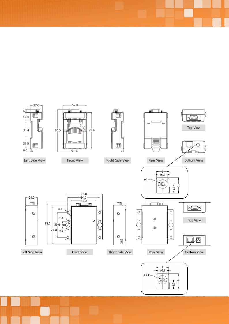
2.4 Dimensions
The following diagrams provide the dimensions of the tDS-700 series module and CA-002 cable that can be used as a reference when defining the specifications and the DC power supply plug for any custom enclosures. All dimensions are in millimeters.
2.4.1 tDS-700 Series Module
tDS-712:
tDSM-712:
Copyright © 2018 ICP DAS CO., Ltd. All Rights Reserved. |
-17 - |

Tiny Serial-to-Ethernet Device Server
tDS-712i/718i-D:
tDS-722(i)/732(i)/715(i)/725(i)/735(i)/718(i)/724(i)/734(i):
Copyright © 2018 ICP DAS CO., Ltd. All Rights Reserved. |
-18 - |
Tiny Serial-to-Ethernet Device Server
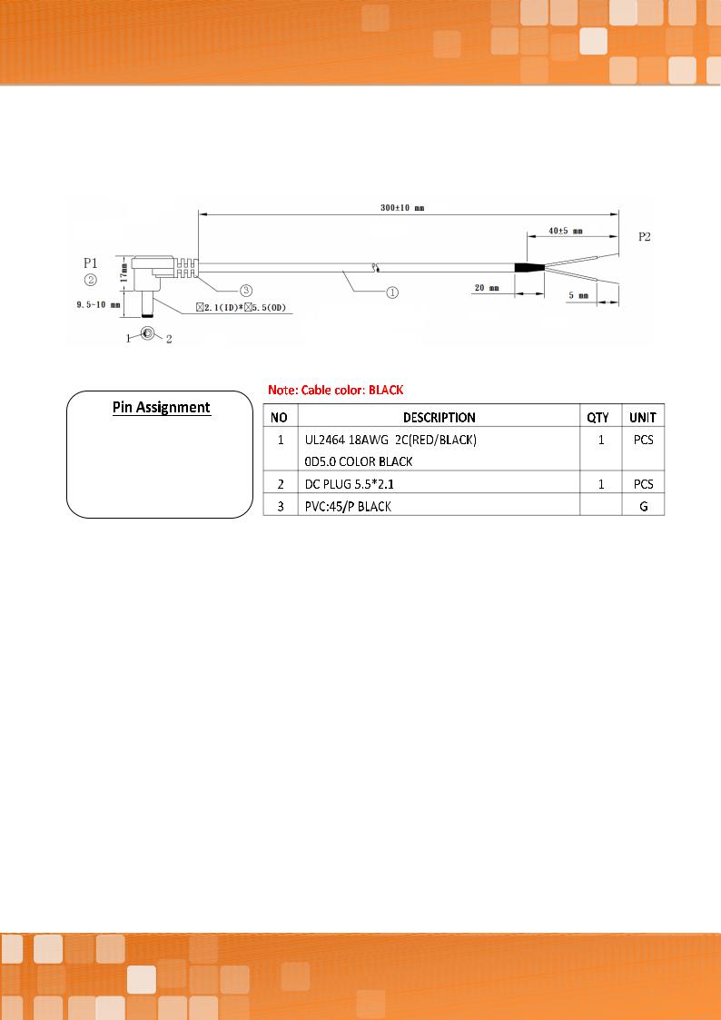
2.4.2CA-002 Cable
P1 |
|
|
P2 |
|
1 |
|
RED |
OPEN |
|
2 |
|
BLACK |
|
OPEN |
Copyright © 2018 ICP DAS CO., Ltd. All Rights Reserved. |
-19 - |
Tiny Serial-to-Ethernet Device Server
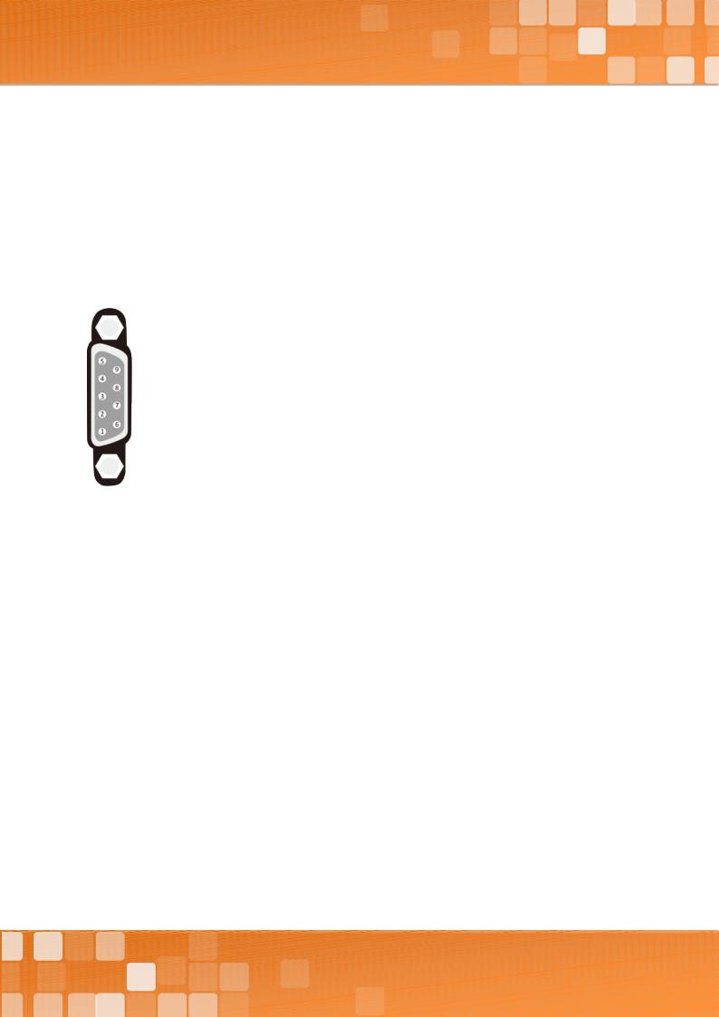
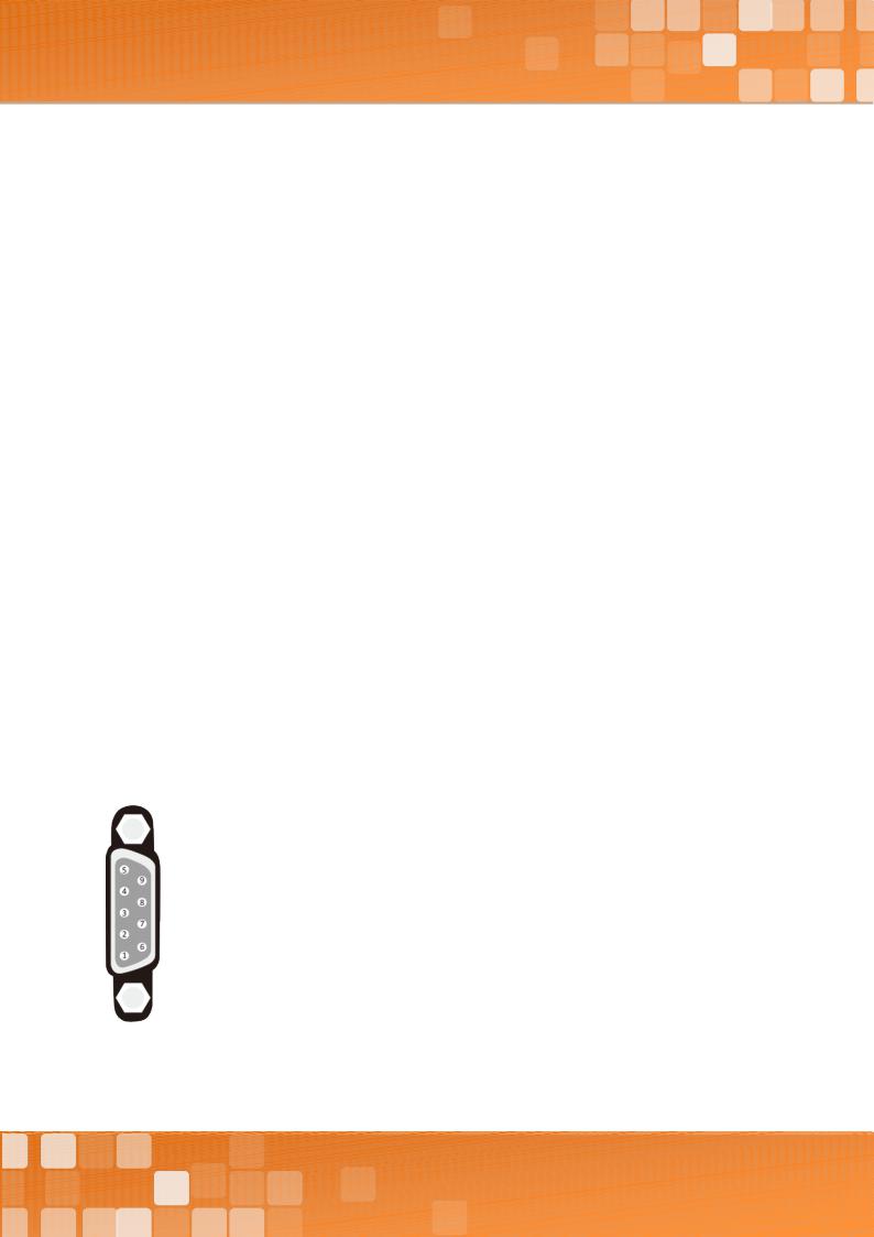
2.5 Pin Assignments
tDS-712/tDS-712i/tDSM-712
|
|
|
|
tDS-712/tDSM-712 |
|
|
tDS-712i |
Terminal No. |
|
|
Pin Assignment |
|
|||
COM1 |
|
09 |
|
N/A |
|
|
N/A |
|
|
|
|
|
|
||
|
|
08 |
|
CTS1 |
|
|
CTS1 |
|
|
07 |
|
RTS1 |
|
|
RTS1 |
|
|
06 |
|
N/A |
|
|
N/A |
|
|
|
|
|
|
||
|
|
05 |
|
GND |
|
|
ISO.GND |
|
|
04 |
|
N/A |
|
|
N/A |
|
|
03 |
|
TxD1 |
|
|
TxD1 |
|
|
|
|
|
|
||
|
|
02 |
|
RxD1 |
|
|
RxD1 |
|
|
01 |
|
N/A |
|
|
N/A |
tDS-722/tDS-722i
|
|
|
|
tDS-722 |
|
|
tDS-722i |
Terminal No. |
|
|
|
Pin Assignment |
|||
|
|
10 |
|
F.G. |
|
|
F.G. |
|
|
|
|
|
|
|
|
|
|
09 |
|
CTS2 |
|
|
CTS2 |
COM2 |
|
08 |
|
RTS2 |
|
|
RTS2 |
|
07 |
|
RxD2 |
|
|
RxD2 |
|
|
|
|
|
|
|||
|
|
|
|
|
|
|
|
|
|
06 |
|
TxD2 |
|
|
TxD2 |
|
|
05 |
|
GND |
|
|
ISO.GND |
|
|
04 |
|
CTS1 |
|
|
CTS1 |
|
|
|
|
|
|
|
|
COM1 |
|
03 |
|
RTS1 |
|
|
RTS1 |
|
|
02 |
|
RxD1 |
|
|
RxD1 |
|
|
01 |
|
TxD1 |
|
|
TxD1 |
Copyright © 2018 ICP DAS CO., Ltd. All Rights Reserved. |
-20 - |
Tiny Serial-to-Ethernet Device Server
tDS-732/tDS-732i
|
|
|
tDS-732 |
|
|
tDS-732i |
Terminal No. |
|
|
|
Pin Assignment |
||
|
10 |
|
F.G. |
|
|
F.G. |
|
|
|
|
|
|
|
|
09 |
|
GND |
|
|
ISO.GND |
COM3 |
08 |
|
RxD3 |
|
|
RxD3 |
|
07 |
|
TxD3 |
|
|
TxD3 |
|
|
|
|
|
|
|
|
06 |
|
GND |
|
|
ISO.GND |
COM2 |
05 |
|
RxD2 |
|
|
RxD2 |
|
04 |
|
TxD2 |
|
|
TxD2 |
|
03 |
|
GND |
|
|
ISO.GND |
COM1 |
02 |
|
RxD1 |
|
|
RxD1 |
|
01 |
|
TxD1 |
|
|
TxD1 |
tDS-715/tDS-715i
|
|
|
|
tDS-715 |
|
|
tDS-715i |
Terminal No. |
|
|
|
Pin Assignment |
|||
|
|
10 |
|
F.G. |
|
|
F.G. |
|
|
|
|
|
|
|
|
|
|
09 |
|
N/A |
|
|
N/A |
|
|
08 |
|
N/A |
|
|
N/A |
|
|
07 |
|
N/A |
|
|
N/A |
|
|
|
|
|
|
|
|
|
|
06 |
|
N/A |
|
|
N/A |
|
|
05 |
|
GND |
|
|
ISO.GND |
|
|
04 |
|
RxD1- |
|
|
RxD1- |
|
|
|
|
|
|
|
|
RS-485/RS-422 |
|
03 |
|
RxD1+ |
|
|
RxD1+ |
|
|
02 |
|
TxD1-/D1- |
|
|
TxD1-/D1- |
|
|
01 |
|
TxD1+/D1+ |
|
|
TxD1+/D1+ |
Copyright © 2018 ICP DAS CO., Ltd. All Rights Reserved. |
-21 - |

Tiny Serial-to-Ethernet Device Server
tDS-725/tDS-725i
|
|
|
tDS-725 |
|
|
tDS-725i |
Terminal No. |
|
|
|
Pin Assignment |
||
|
10 |
|
F.G. |
|
|
F.G. |
|
|
|
|
|
|
|
|
09 |
|
N/A |
|
|
N/A |
|
08 |
|
N/A |
|
|
N/A |
|
07 |
|
N/A |
|
|
N/A |
|
|
|
|
|
|
|
|
06 |
|
GND |
|
|
ISO.GND |
COM2 |
05 |
|
D2- |
|
|
D2- |
|
04 |
|
D2+ |
|
|
D2+ |
|
03 |
|
GND |
|
|
ISO.GND |
COM1 |
02 |
|
D1- |
|
|
D1- |
|
01 |
|
D1+ |
|
|
D1+ |
tDS-735/tDS-735i
|
|
|
tDS-735 |
|
|
tDS-735i |
Terminal No. |
|
|
|
Pin Assignment |
||
|
10 |
|
F.G. |
|
|
F.G. |
|
|
|
|
|
|
|
|
09 |
|
GND |
|
|
ISO.GND |
COM3 |
08 |
|
D3- |
|
|
D3- |
|
07 |
|
D3+ |
|
|
D3+ |
|
|
|
|
|
|
|
|
06 |
|
GND |
|
|
ISO.GND |
COM2 |
05 |
|
D2- |
|
|
D2- |
|
04 |
|
D2+ |
|
|
D2+ |
|
03 |
|
GND |
|
|
ISO.GND |
COM1 |
02 |
|
D1- |
|
|
D1- |
|
01 |
|
D1+ |
|
|
D1+ |
Copyright © 2018 ICP DAS CO., Ltd. All Rights Reserved. |
-22 - |
Tiny Serial-to-Ethernet Device Server
tDS-718/tDS-718i
|
|
|
|
tDS-718 |
|
|
tDS-718i |
Terminal No. |
|
|
|
Pin Assignment |
|||
|
|
10 |
|
F.G. |
|
|
F.G. |
|
|
|
|
|
|
|
|
|
|
09 |
|
N/A |
|
|
N/A |
|
|
08 |
|
GND |
|
|
ISO.GND |
RS-232 |
|
07 |
|
RxD1 |
|
|
RxD1 |
|
|
|
|
|
|
|
|
|
|
06 |
|
TxD1 |
|
|
TxD1 |
|
|
05 |
|
GND |
|
|
ISO.GND |
|
|
04 |
|
RxD1- |
|
|
RxD1- |
|
|
|
|
|
|
|
|
RS-485/RS-422 |
|
03 |
|
RxD1+ |
|
|
RxD1+ |
|
|
02 |
|
TxD1-/D1- |
|
|
TxD1-/D1- |
|
|
01 |
|
TxD1/D1+ |
|
|
TxD1/D1+ |
tDS-718i-D
|
|
|
|
RS-232 |
|
RS-422 |
RS-485 |
|
|
|
|
|
|
|
|
Terminal No. |
|
|
|
|
Pin Assignment |
|
|
COM1 |
|
09 |
|
- |
|
- |
- |
|
|
08 |
|
CTS |
|
- |
- |
|
|
|
|
|
|
|
|
|
|
07 |
|
RTS |
|
- |
- |
|
|
06 |
|
- |
|
- |
- |
|
|
05 |
|
GND |
|
GND |
GND |
|
|
|
|
|
|
|
|
|
|
04 |
|
- |
|
RxD- |
- |
|
|
03 |
|
TxD |
|
RxD+ |
- |
|
|
02 |
|
RxD |
|
TxD+ |
Data+ |
|
|
|
|
|
|
|
|
|
|
01 |
|
- |
|
TxD- |
Data- |
Copyright © 2018 ICP DAS CO., Ltd. All Rights Reserved. |
-23 - |

Tiny Serial-to-Ethernet Device Server
tDS-724/tDS-724i
|
|
|
|
tDS-724 |
|
|
tDS-724i |
Terminal No. |
|
|
|
Pin Assignment |
|||
|
|
10 |
|
F.G. |
|
|
F.G. |
|
|
|
|
|
|
|
|
|
|
09 |
|
GND |
|
|
ISO.GND |
|
|
08 |
|
CTS2 |
|
|
CTS2 |
|
|
07 |
|
RTS2 |
|
|
RTS2 |
|
|
|
|
|
|
|
|
COM2 |
|
06 |
|
GND |
|
|
ISO.GND |
|
|
05 |
|
RxD2 |
|
|
RxD2 |
|
|
04 |
|
TxD2 |
|
|
TxD2 |
|
|
03 |
|
GND |
|
|
ISO.GND |
COM1 |
|
02 |
|
D1- |
|
|
D1- |
|
|
01 |
|
D1+ |
|
|
D1+ |
tDS-734/tDS-734i
|
|
|
tDS-734 |
|
|
tDS-734i |
Terminal No. |
|
|
|
Pin Assignment |
||
|
10 |
|
F.G. |
|
|
F.G. |
|
|
|
|
|
|
|
|
09 |
|
GND |
|
|
ISO.GND |
COM3 |
08 |
|
RxD3 |
|
|
RxD3 |
|
07 |
|
TxD3 |
|
|
TxD3 |
|
|
|
|
|
|
|
|
06 |
|
GND |
|
|
ISO.GND |
COM2 |
05 |
|
RxD2 |
|
|
RxD2 |
|
04 |
|
TxD2 |
|
|
TxD2 |
|
03 |
|
GND |
|
|
ISO.GND |
COM1 |
02 |
|
D1- |
|
|
D1- |
|
01 |
|
D1+ |
|
|
D1+ |
Copyright © 2018 ICP DAS CO., Ltd. All Rights Reserved. |
-24 - |
Tiny Serial-to-Ethernet Device Server
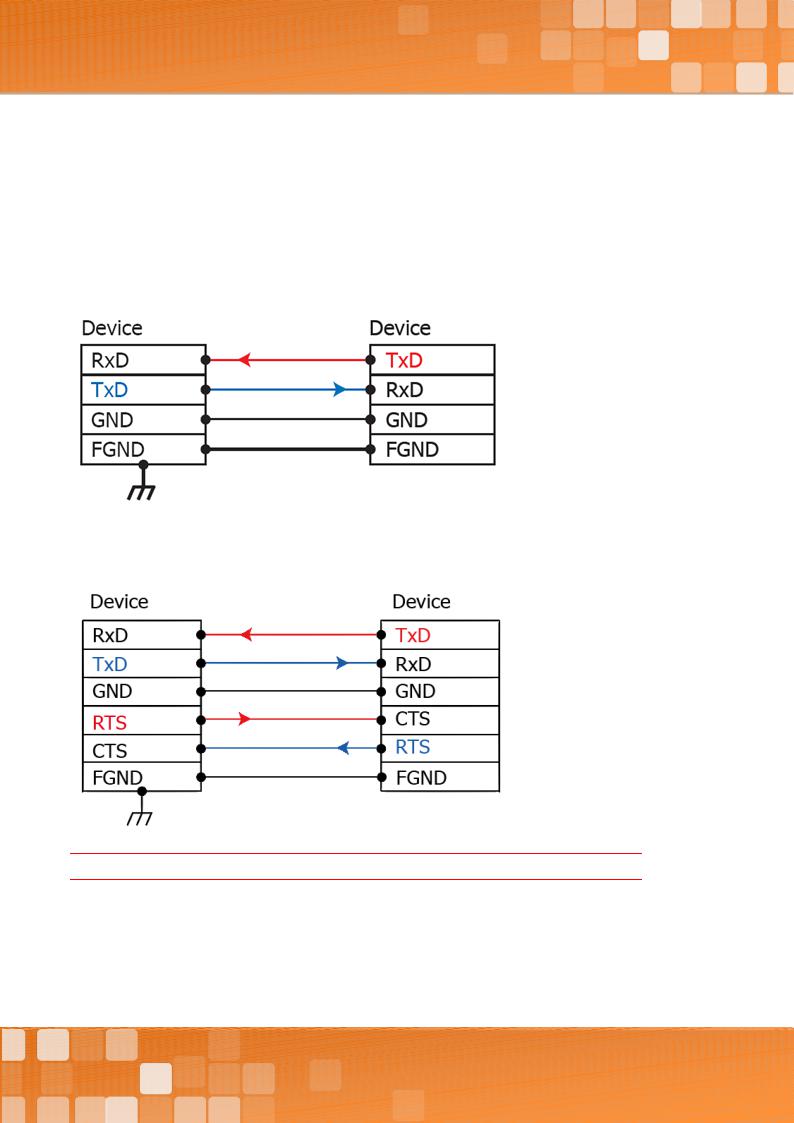
2.6 Wiring Notes for RS-232/485/422 Interfaces
RS-232 Wiring
3-wire RS-232 Connection
5-wire RS-232 Connection
Note: FGND is the frame ground that is soldered to the metal shield on the DB-9 cable.
Copyright © 2018 ICP DAS CO., Ltd. All Rights Reserved. |
-25 - |
Tiny Serial-to-Ethernet Device Server
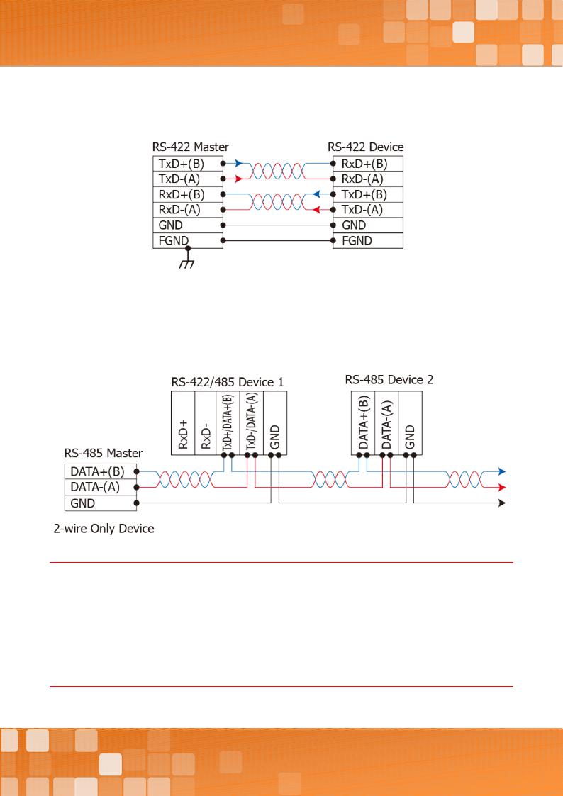
RS-422 Wiring
RS-485 Wiring
Notes:
1.Usually, you have to connect all signal grounds of RS-422/485 devices together to reduce common-mode voltage between devices.
2.Twisted-pair cable must be used for the DATA+/- wires.
3.Both two ends of the cable may require a termination resistor connected across the two wires (DATA+ and DATA-). Typically 120 Ω resisters are used.
4.The Data+ and B pins are positive-voltage pins, and Dataand A pins are negative-voltage pins in the above figure. The B/A pinsmay be defined in anotherway depending on devices, please check it first.
Copyright © 2018 ICP DAS CO., Ltd. All Rights Reserved. |
-26 - |
 Loading...