


INSTRUCTION MANUAL
FM TRANSCEIVER
iV85 iV85-T
This device complies with Part 15 of the FCC Rules. Operation is subject to the following two conditions: (1) this device may not cause harmful interference, and (2) this device must accept any interference received, including interference that may cause undesired operation.

FOREWORD
Thank you for purchasing this Icom transceiver. The IC-V85 FM TRANSCEIVER is designed and built with Icom’s superior technology and craftsmanship. With proper care, this transceiver should provide you with years of trouble-free operation.
We want to take a couple of moments of your time to thank you for making the IC-V85 your radio of choice, and hope you agree with Icom’s philosophy of “technology first.” Many hours of research and development went into the design of your ICV85.
DFEATURES
7 W*— high transmit output power
*7 W : IC-V85 except [THA] version,
5.5W : IC-V85 [THA] version
CTCSS and DTCS encoder/decoder standard
Optional DTMF decoder
IMPORTANT
READ ALL INSTRUCTIONS carefully and completely before using the transceiver.
SAVE THIS INSTRUCTION MANUAL— This instruction manual contains important operating instructions for the IC-V85.
EXPLICIT DEFINITIONS
WORD |
DEFINITION |
Personal injury, fire hazard or electric shock R WARNING! may occur.
CAUTION Equipment damage may occur. |
||
NOTE |
Recommended for optimum use. No risk of |
|
personal injury, fire or electric shock. |
||
|
||
Icom, Icom Inc. and the 
 logo are registered trademarks of Icom Incorporated (Japan) in the United States, the United Kingdom, Germany, France, Spain, Russia and/or other countries.
i

PRECAUTIONS
RWARNING RF EXPOSURE! This device emits
Radio Frequency (RF) energy. Extreme caution should be observed when operating this device. If you have any questions regarding RF exposure and safety standards please refer to the Federal Communications Commission Office of Engineering and Technology’s report on Evaluating Compliance with FCC Guidelines for Human Radio frequency Electromagnetic Fields (OET Bulletin 65)
RWARNING! NEVER hold the transceiver so that the antenna is very close to, or touching exposed parts of the body, especially the face or eyes, while transmitting. The transceiver will perform best if the microphone is 5 to 10 cm (2 to 4 inches) away from the lips and the transceiver is vertical.
RWARNING! NEVER operate the transceiver with a headset or other audio accessories at high volume levels. Hearing experts advise against continuous high volume operation. If you experience a ringing in your ears, reduce the volume or discontinue use.
RWARNING! NEVER operate the transceiver while driving a vehicle. Safe driving requires your full attention— anything less may result in an accident.
RWARNING! NEVER connect the transceiver to an AC outlet. This may pose a fire hazard or result in an electric shock.
NEVER connect a power supply of more than 16 V DC through the optional CP-19R CIGARETTE LIGHTER CABLE to the [DC 11V] jack to prevent damaging the transceiver.
NEVER connect the transceiver to a power source using reverse polarity. This will ruin the transceiver.
NEVER cut the DC power cable between the DC plug and fuse holder. If an incorrect connection is made after cutting, the transceiver may be damaged.
NEVER expose the transceiver to rain, snow or any liquids. The transceiver may be damaged.
NEVER operate or touch the transceiver with wet hands. This may result in an electric shock or ruin the transceiver.
NEVER attempt to charge alkaline or dry cell batteries. Be aware that external DC power connections will charge batteries inside the battery case. This will damage not only the battery case but also the transceiver.
DO NOT push the PTT when not actually desiring to transmit.
ii
PRECAUTIONS—continued
DO NOT operate the transceiver near unshielded electrical blasting caps or in an explosive atmosphere.
BE CAREFUL! The transceiver will become hot when operating it continuously for long periods.
AVOID using or placing the transceiver in direct sunlight or in areas with temperatures below –10°C (+14˚F) or above +60°C (+140˚F).
Place the unit in a secure place to avoid inadvertent use by children.
AVOID the use of chemical agents such as benzine or alcohol when cleaning, as they can damage the transceiver’s surfaces.
Even when the transceiver power is OFF, a slight current still flows in the circuits. Remove the battery pack or case from the transceiver when not using it for a long time. Otherwise, the battery pack (Li-Ion: BP-227) or installed batteries will become exhausted.
For USA only:
Caution: Changes or modifications to this transceiver, not expressly approved by Icom Inc., could void your authority to operate this transceiver under FCC regulations.
iii
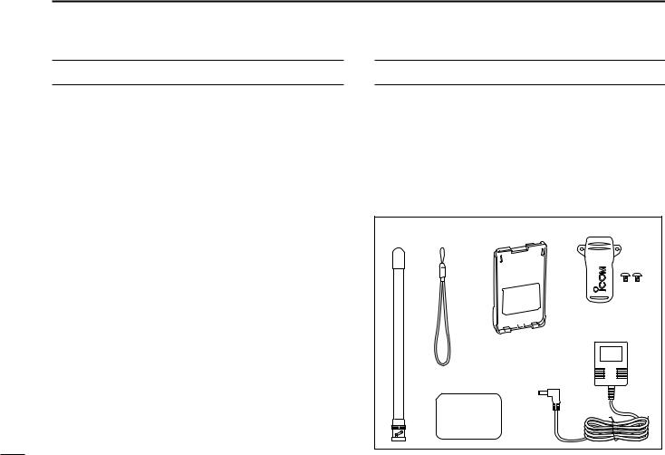
SUPPLIED ACCESSORIES
q Antenna* . . . . . . . . . . . . . . . . . . . . . . . . . . . . . . . . . . . . . 1 w Hand strap* . . . . . . . . . . . . . . . . . . . . . . . . . . . . . . . . . . . 1 e 2251 OPT sheet*. . . . . . . . . . . . . . . . . . . . . . . . . . . . . . . 1 r Battery pack*/Battery case* . . . . . . . . . . . . . . . . . . . . . . 1 t Belt clip* (with screws) . . . . . . . . . . . . . . . . . . . . . . . . . . 1 y AC Adapter*. . . . . . . . . . . . . . . . . . . . . . . . . . . . . . . . . . . 1
*Not supplied with some versions.
q |
w |
r |
t |
y
e

OPTION LIST
•BP-226 BATTERY CASE
Battery case for 5×AA (LR6) size alkaline batteries.
•BP-227 LI-ION BATTERY PACK
7.2 V/1700 mAh Lithium-Ion battery pack.
•BC-119N DESKTOP CHARGER + AD-100 CHARGER ADAPTER
For rapid charging of battery packs. An AC adapter is supplied with the charger. Charging time: approx. 2–2.5 hrs.
•BC-121N MULTI-CHARGER + AD-100 CHARGER ADAPTER
(6 pcs.)
For rapid charging of up to 6 battery packs (six AD-100’s are required) simultaneously. An AC adapter may be supplied depending on version. Charging time: approx. 2–2.5 hrs.
•CP-19R CIGARETTE LIGHTER CABLE WITH NOISE FILTER
Used for operation and charging a battery pack connected to transceiver via a DC power source. (11.7 V–15.9 V DC)
•MB-98 BELT CLIP
MB-98: Same as that supplied with the transceiver.
•UT-108 DTMF DECODER UNIT
Provides pager and code squelch capabilities.
•SP-13 EARPHONE
Provides clear receive audio in noisy environments.
•FA-B2E WHIP ANTENNA
Same as that supplied with transceiver.
•HM-75A/HM-131L/HM-158L SPEAKER-MICROPHONES
Combination speaker-microphones that provide convenient operation while hanging the transceiver from your belt. HM-75A has 4 function switches for remote control capabilities. HM-131L/HM-158L are equipped with an earphone jack and a revolving clip.
•HM-128L/HM-153L/HM-166L EARPHONE-MICROPHONE
You can clip the microphone with PTT switch to your lapel or breast pocket.
•HS-85 HEADSET
Allows you hands-free operation. Includes VOX, PTT and “one-touch” PTT with time-out timer.
•VS-1L PTT/VOX UNIT+HS-94 HEADSET
VS-1L PTT/VOX UNIT
Required when using the headset. HS-94 EAR-PIECE TYPE HEADSET
Earhook headset with flexible boom microphone.
•CS-V85 CLONING SOFTWARE+OPC-478/U/UC CLONING CABLE
Provide quick and easy programming of memory channel, memory name etc.
•OPC-474 CLONING CABLE
For cloning between transceivers.
•LC-167 CARRYING CASE
Helps protect the transceiver from scratches, etc..
iv

TABLE OF CONTENTS
FOREWORD ........................................................................ |
i |
|
IMPORTANT......................................................................... |
i |
|
EXPLICIT DEFINITIONS...................................................... |
i |
|
PRECAUTIONS .............................................................. |
ii–iii |
|
SUPPLIED ACCESSORIES ............................................... |
iii |
|
OPTION LIST .................................................................... |
iv |
|
TABLE OF CONTENTS .................................................. |
v–vi |
|
QUICK REFERENCE GUIDE ......................................... |
I–VI |
|
|
■ Preparation................................................................... |
I |
|
■ Your first contact ........................................................ |
IV |
|
■ Repeater operation ..................................................... |
V |
|
■ Programming memory channels................................ |
VI |
1 |
ACCESSORIES.......................................................... |
1–2 |
|
■ Accessory attachment................................................. |
1 |
2 |
PANEL DESCRIPTION .............................................. |
3–8 |
|
■ Switches, controls, keys and connectors .................... |
3 |
|
■ Function display .......................................................... |
7 |
3 |
BATTERY PACKS .................................................... |
9–16 |
|
■ Battery pack replacement ........................................... |
9 |
|
■ Cautions .................................................................... |
11 |
|
■ Regular charging ...................................................... |
13 |
|
■ Rapid charging ......................................................... |
14 |
|
■ External DC power operation .................................... |
16 |
v
4 |
BASIC OPERATION............................................... |
17–21 |
|
■ Power ON.................................................................. |
17 |
|
■ VFO mode selection.................................................. |
17 |
|
■ Setting a frequency ................................................... |
17 |
|
■ Setting audio/squelch level ....................................... |
19 |
|
■ Receive and transmit ................................................ |
19 |
|
■ Monitor function......................................................... |
19 |
|
■ Display type............................................................... |
20 |
|
■ Key lock function ....................................................... |
20 |
|
■ Weather channel operation |
|
|
(USA version only) .................................................... |
21 |
5 |
REPEATER OPERATION ...................................... |
22–25 |
|
■ General ..................................................................... |
22 |
|
■ Reversed duplex mode ............................................. |
22 |
|
■ Offset frequency........................................................ |
23 |
|
■ Subaudible tones ...................................................... |
23 |
|
■ Repeater lockout ....................................................... |
24 |
|
■ Auto repeater function (USA version only) ................ |
25 |
6 |
MEMORY/CALL OPERATION ............................... |
26–31 |
|
■ General description ................................................... |
26 |
|
■ Selecting a memory channel..................................... |
26 |
|
■ Selecting the call channel ......................................... |
26 |
|
■ Programming the memory/call channels................... |
27 |
|
■ Channel name programming..................................... |
28 |
|
■ Memory transfers ...................................................... |
28 |

|
■ Memory bank selection ............................................. |
30 |
|
■ Memory bank setting................................................. |
30 |
|
■ Transferring bank contents........................................ |
31 |
7 DTMF MEMORY..................................................... |
32–34 |
|
|
■ Programming a DTMF code sequence ..................... |
32 |
|
■ Transmitting a DTMF code sequence ....................... |
33 |
|
■ DTMF transmission rate............................................ |
34 |
8 |
SCAN OPERATION................................................ |
35–38 |
|
■ Scan types ................................................................ |
35 |
|
■ Programmed scan..................................................... |
35 |
|
■ Memory scan.............................................................. |
36 |
|
■ Skip channels............................................................ |
37 |
|
■ Scan resume condition.............................................. |
37 |
|
■ Priority watch............................................................. |
38 |
9 |
SUBAUDIBLE TONES........................................... |
39–42 |
|
■ Tone squelch ............................................................. |
39 |
|
■ Pocket beep operation .............................................. |
41 |
|
■ Tone scan.................................................................. |
42 |
10PAGER/CODE SQUELCH |
|
|
|
(Requires Optional UT-108).................................. |
43–46 |
|
■ Pager function ........................................................... |
43 |
|
■ Code programming ................................................... |
43 |
|
■ Pager operation......................................................... |
45 |
|
■ Code squelch ............................................................ |
46 |
11 SET MODES........................................................... |
47–56 |
■ SET MODE ............................................................... |
47 |
■ INITIAL SET MODE .................................................. |
51 |
12 SET MODE INSPECTION ...................................... |
57–58 |
13 CLONING ............................................................... |
59–60 |
■ Transceiver-to-transceiver cloning ............................ |
59 |
■ Cloning using a PC ................................................... |
60 |
14 RESETTING FUNCTIONS ........................................... |
61 |
■ Partial reset ............................................................... |
61 |
■ CPU reset.................................................................. |
61 |
15 TROUBLESHOOTING ................................................. |
62 |
16 OPTION ........................................................................ |
63 |
■ Optional UT-108 installation ...................................... |
63 |
17 SPECIFICATIONS........................................................ |
64 |
■ General ..................................................................... |
64 |
■ Transmitter ................................................................ |
64 |
■ Receiver .................................................................... |
64 |
18 CE........................................................................... |
65–66 |
1
2
3
4
5
6
7
8
9
10
11
12
13
14
15
16
17
18
19
vi
QUICK REFERENCE GUIDE
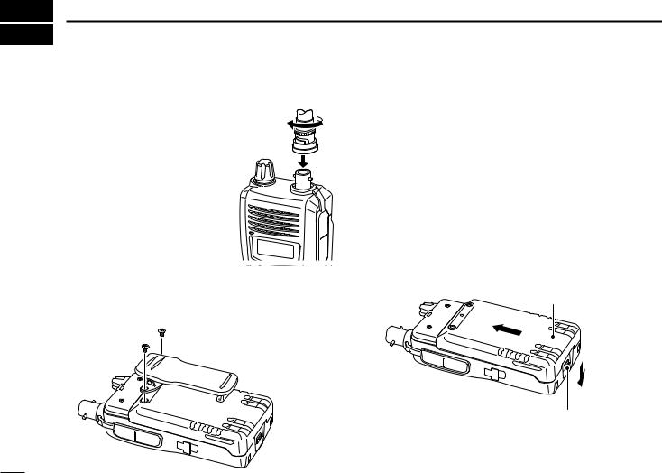
■ Preparation
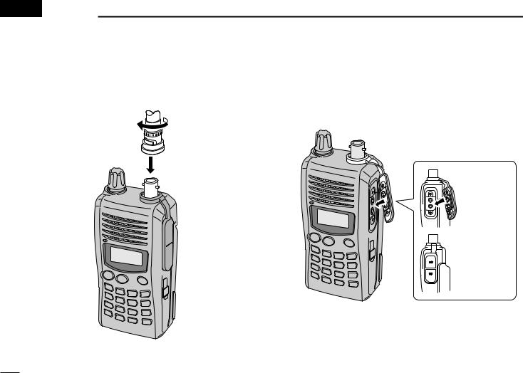
D Antenna
Attach the antenna to the transceiver as illustrated at right.
D Belt clip
Conveniently attaches to your belt.
Attach the belt clip with the supplied screws using a phillips screwdriver.
To attach the belt clip
D Battery pack replacement
Before replacing the battery pack, push and hold [PWR] for 1 sec. to turn the power OFF.
• To attach the battery pack
Slide the battery pack on the back of the transceiver in the direction of the arrow (q), then lock it with the battery release button.
•Slide the battery pack until the battery release button makes a ‘click’ sound.
•To release the battery pack
Push the battery release button in the direction of the arrow (w) as shown below. The battery pack is then released.
Battery pack
q
w |
Battery release button
I
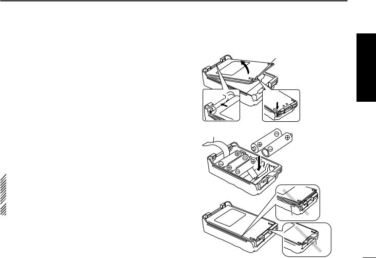
D Battery case— optional for some versions
When using a BP-226 BATTERY CASE attached to the transceiver, install 5 AA (LR6) size alkaline batteries as illustrated at right.
q Hook your finger under the latch, and open the cover in the direction of the arrow (q). (Fig.1)
wThen, install 5 × AA (LR6) size alkaline batteries. (Fig.2)
•Install the alkaline batteries only.
•Be sure to observe the correct polarity.
•Do not pin the ribbon under the batteries.
eClose the cover with fitting in the direction of the arrow (w) first, then firm the latch in place (e). (Fig.1)
•Be sure to the gasket and the ribbon are set correctly, and do not protrude out of the battery case. (Fig.3)
 R CAUTION!
• When installing batteries, make sure they are all the
same brand, type and capacity. Also, do not mix new and
old batteries together.
 • Keep battery contacts clean. It’s a good idea to clean battery terminals once a week.
QUICK REFERENCE GUIDE
Fig.1 |
BP-226 Latch |
w
 e
e
Fig.2
Ribbon
Fig.3
Gasket

 Ribbon
Quick reference guide
II
QUICK REFERENCE GUIDE
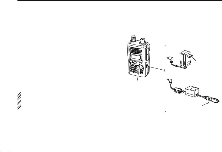
D Regular charging
When using a BP-227 BATTERY PACK attached to the transceiver, prior to using the transceiver for the first time, the battery pack must be fully charged for optimum life and operation.
DCharging note
•Be sure to turn the transceiver power OFF.
Otherwise the battery pack will not be charged completely or takes longer charging time periods.
•External DC power operation becomes possible when using an optional CP-19R. The attached battery pack is also charged simultaneously, except during transmit. (see p. 16 for more details)
 Even through there is no indication during regular charg-
ing, the transceiver automatically stops charging the bat-
 tery pack when the battery pack is fully charged (BP-227’s
  voltage becomes approx. 7.2 V) or the continuous charg-
  ing time is over 15 hours.
Transceiver
|
• BC-167A/D |
to |
|
[DC 11V] |
to AC outlet |
|
• CP-19R (Optional) |
Turn power OFF while charging the battery pack.
• Charging time period: |
|
Approx. 12–13 hours |
to cigarette lighter |
|
socket (12 V DC) |
III
■ Your first contact
Now that you have your IC-V85 ready, you are excited to get on the air. We would like to walk you through a few basic operational steps to make your first “On The Air” use an enjoyable experience.
D About default setting
The [VOL] control function can be exchanged with [Y]/[Z] keys function in INITIAL SET MODE. However, in this QUICK REFERENCE, the factory default setting ([VOL] controls audio output level) is used to simplify instructions.
D Basic operation
1. Turning ON the transceiver
Although you have purchased a brand new transceiver, some settings may be changed from the factory defaults because of the Quality Control
process. Resetting the CPU is necessary to start from factory default.
While pushing [MONI] |
|
|
|
|
|
|
and [CLR], push and |
|
|
|
|
|
PWR |
hold [PWR] for 1 sec. to |
|
|
|
|
|
|
|
|
|
|
|
D |
|
reset the CPU and turn |
MONI |
|
|
|
PWR |
|
A |
B |
C |
D |
CLR |
||
power ON. |
|
FUNC |
CALL |
MR |
|
|
|
1 |
2 |
3 |
|
|
|
|
|
TONE |
P.BEEP T.SCAN |
|
|
|
DUP |
SCAN |
SKIP |
OPT |
4 |
5 |
6 |
0 |
PRIO |
SET |
H/M/L |
|
7 |
8 |
9 |
ENT |
QUICK REFERENCE GUIDE
2. Adjusting audio output level
Rotate [VOL] to set the desired audio level.
3. Adjusting the squelch level
While pushing and holding [MONI], push [Y] or [Z] to set the squelch level.
|
|
|
|
guide |
[VOL] |
|
|
|
referenceQuick |
|
|
|
|
|
MONI |
|
|
|
PWR |
A |
B |
C |
D |
|
|
FUNC |
CALL |
MR |
CLR |
|
TONE |
P.BEEP |
T.SCAN |
BANK |
|
1 |
2 |
3 |
|
|
DUP |
SCAN |
SKIP |
OPT |
|
4 |
5 |
6 |
0 |
|
PRIO |
SET |
H/M/L |
|
|
7 |
8 |
9 |
ENT |
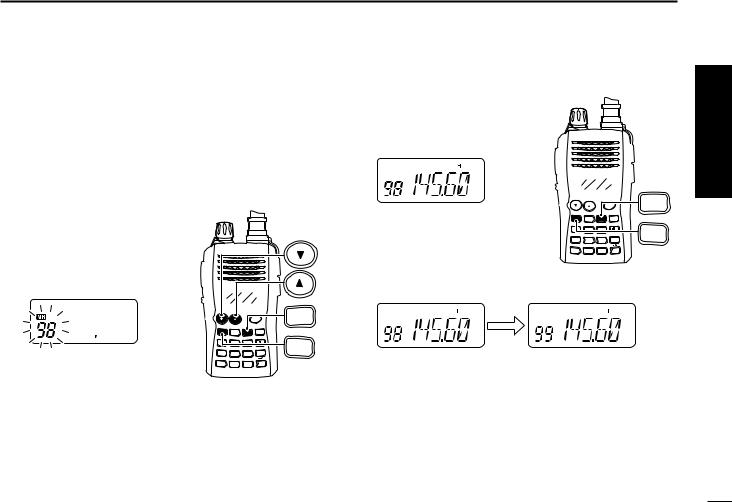
4. Tune the desired frequency
The up/down keys, [Y]/[Z], will allow you to tune to the frequency that you want to operate on. Page 18 will instruct you on how to adjust the tuning step size.
Push [Y] or [Z] to adjust the frequency.
PWR
A |
B |
C |
D |
FUNC |
CALL |
MR |
CLR |
TONE |
P.BEEP |
T.SCAN |
BANK |
1 |
2 |
3 |
|
DUP |
SCAN |
SKIP |
OPT |
4 |
5 |
6 |
0 |
PRIO |
SET |
H/M/L |
|
7 |
8 |
9 |
ENT |
|
IV

QUICK REFERENCE GUIDE
Direct frequency input from the keypad is also available.
To enter the desired frequency, enter 6 digits starting from the 100 MHz digit.
•Entering three* to five digits then pushing [ ENT] will also set the frequency. (*Some versions only requires two digits.)
•When a digit is mistakenly input, push [CLR] to abort input.
|
|
|
PWR |
A |
B |
C |
D |
FUNC |
CALL |
MR |
|
TONE |
P.BEEP |
T.SCAN |
BANK |
1 |
2 |
3 |
|
DUP |
SCAN |
SKIP |
OPT |
4 |
5 |
6 |
0 |
PRIO |
SET |
H/M/L |
|
7 |
8 |
9 |
|
D
CLR
 ENT
ENT
Keypad
• Example 1— when entering 145.525 MHz
|
TONE |
DUP |
SCAN |
SCAN |
P.BEEP |
SCAN |
|
|
5 |
||||||
Push |
1 |
4 |
5 |
5 |
2 |
||
|
• Example 2— when entering 144.800 MHz
Push |
TONE |
DUP |
DUP |
SET |
OPT |
|
1 |
4 |
4 |
8 |
0 |
ENT |
5. Transmit and receive
Push and hold [PTT] to transmit, then speak into the microphone; release to receive.
V
■ Repeater operation
1. Setting duplex
Push [FUNC], then [DUP](4) several times to select minus duplex or plus duplex.
• The USA version has an auto repeater function, therefore, setting duplex is not required.
|
|
|
PWR |
A |
|
A |
B |
C |
D |
FUNC |
|
FUNC |
CALL |
MR |
CLR |
||
TONE |
P.BEEP |
T.SCAN |
BANK |
|
|
1 |
2 |
3 |
|
|
|
DUP |
SCAN |
SKIP |
OPT |
DUP |
|
4 |
5 |
6 |
0 |
||
4 |
|||||
PRIO |
SET |
H/M/L |
|
||
7 |
8 |
9 |
ENT |
||
|
2. Repeater tone
Push [FUNC], then [TONE](1) several times until “ ” appears, if required.
|
|
|
PWR |
A |
A |
B |
C |
D |
FUNC |
FUNC |
CALL |
MR |
CLR |
|
TONE |
P.BEEP |
T.SCAN |
BANK |
|
1 |
2 |
3 |
|
|
DUP |
SCAN |
SKIP |
OPT |
TONE |
4 |
5 |
6 |
0 |
|
PRIO |
SET |
H/M/L |
|
1 |
7 |
8 |
9 |
ENT |
|
QUICK REFERENCE GUIDE
■ Programming memory channels
The IC-V85 has a total of 107 memory channels (including 6 scan edges and 1 call channel) for storing often used operating frequency, repeater settings, etc.
1. Setting frequency
In VFO mode, set the desired operating frequency with other desired settings, such as repeater and subaudible tone.
2. Selecting a memory channel
Push [FUNC] and [MR] then push [Y] or [Z] several times to select the desired memory channel.
•“X” indicator and memory channel number blink.
|
|
|
|
C |
|
|
|
|
PWR |
MR |
|
A |
B |
C |
D |
A |
|
FUNC |
CALL |
MR |
CLR |
||
TONE |
P.BEEP |
T.SCAN |
BANK |
||
|
|||||
1 |
2 |
3 |
|
FUNC |
|
DUP |
SCAN |
SKIP |
OPT |
||
4 |
5 |
6 |
0 |
|
|
PRIO |
SET |
H/M/L |
|
|
|
7 |
8 |
9 |
ENT |
|
|
|
|
3. Writing a memory channel
Push [FUNC], then push and hold [MR] for 1 sec. to program.
• 3 beeps sound.
|
C |
PWR |
MR |
A |
B |
C |
D |
A |
FUNC |
CALL |
MR |
CLR |
|
TONE |
P.BEEP |
T.SCAN |
BANK |
|
1 |
2 |
3 |
|
FUNC |
DUP |
SCAN |
SKIP |
OPT |
|
4 |
5 |
6 |
0 |
|
PRIO |
SET |
H/M/L |
|
|
7 |
8 |
9 |
ENT |
|
•Continue to push and hold [MR] for 1 sec. after 3 beeps are emitted, to increment the displayed memory channel number.
Quick reference guide
VI
 1 ACCESSORIES
■ Accessory attachment
D Antenna
Attach the antenna to the transceiver as illustrated below.
Keep the [SP/MIC] cap (SP/MIC jack cover) attached when jacks are not in use to keep the contacts clean.
Attach the [SP/MIC] cap.

 [SP/MIC] cap
1
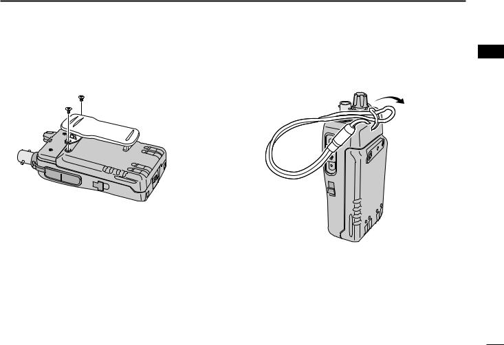
D Belt clip
Conveniently attaches to your belt.
Attach the belt clip with the supplied screws using a phillips screwdriver.
To attach the belt clip
ACCESSORIES 1
D Hand strap
Slide the hand strap through the loop on the top of the rear panel as illustrated below. Facilitates carrying.
1
2
3
4
5
6
7
8
9
10
11
12
13
14
15
16
17
18
19
2
 2 PANEL DESCRIPTION
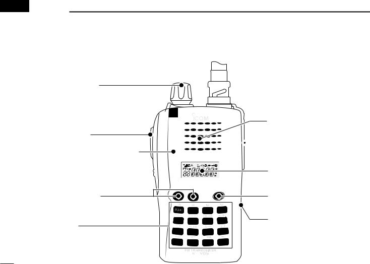
■ Switches, controls, keys and connectors
q CONTROL DIAL
w PTT SWITCH
Microphone
e SQUELCH/MONITOR SWITCH 
r UP/DOWN KEYS
t KEYPAD
 !0ANTENNA CONNECTOR
Speaker
 o EXTERNAL SPEAKER/
MICROPHONE JACKS
i FUNCTION DISPLAY
u POWER KEY
y EXTERNAL DC JACK
3

q CONTROL DIAL [VOL] (p. 19) Rotate to adjust the volume level.
 The assigned function for [VOL] and [Y]/[Z] can be ex-
  changed in INITIAL SET MODE (pgs. 18, 53).
w PTT SWITCH [PTT]
Push and hold to transmit; release to receive.
e SQUELCH/MONITOR SWITCH [MONI] (p. 19)
Push and hold to open the squelch temporarily and monitor the operating frequency.
While pushing and holding this key, push [Y] or [Z] to adjust the squelch level.
 The assigned function for [VOL] and [Y]/[Z] can be
  exchanged in INITIAL SET MODE (pgs. 18, 53).
rUP/DOWN KEYS [Y]/[Z] (p.18)
Selects the operating frequency, set mode items, etc.
 The assigned function for [VOL] and [Y]/[Z] can be ex-
 changed in INITIAL SET MODE (pgs. 18, 53).
t KEYPAD (pgs. 5, 6)
Used to enter operating frequency, the DTMF codes, etc.
PANEL DESCRIPTION 2
y EXTERNAL DC JACK [DC 11V]
Connect an external DC power supply through the optional CP-19R for external DC operation. (p. 16)
Connect the supplied (or optional) wall charger, BC167A/D, to charge the attached battery pack. (p. 13)
u POWER KEY [PWR] (p. 17)
Push and hold for 1 sec. to turn the power ON and OFF.
i FUNCTION DISPLAY (pgs. 7, 8)
o EXTERNAL SPEAKER/MICROPHONE JACKS [SP/MIC]
Connect an optional speaker-microphone or headset, if desired. The internal microphone and speaker will not function when a connector is inserted.
See page iv for a list of available options.
!0ANTENNA CONNECTOR (p. 1)
Connects the supplied antenna.
1
2
3
4
5
6
7
8
9
10
11
12
13
14
15
16
17
18
19
4

2 PANEL DESCRIPTION
D Keypad
A FUNC TONE 1 DUP 4 PRIO 7
B CALL P.BEEP 2 SCAN 5 SET 8
C
MR
T.SCAN 3 SKIP 6 H/M/L 9
D CLR BANK
OPT 0
 ENT
ENT
A |
[FUNC] |
|
|
FUNC |
Access to secondary function. |
B |
[CALL] |
CALL |
Selects the call channel. (p. 26) |
C |
[MR] |
MR |
Selects a memory mode. (p. 26) |
|
After pushing [FUNC], enter into memory pro- |
|
gramming/editing mode. (pgs. 27–29) |
|
After pushing [FUNC], programs/transfers |
|
VFO/memory or call channel contents into |
|
memory channel/VFO when pushed and held |
|
for 1 sec. (pgs. 27–29) |
D |
[CLR] |
CLR |
Selects VFO mode, aborts direct frequency input, |
|
or cancels scanning, etc. (pgs. 17, 35) |
TONE 1
P.BEEP 2
T.SCAN 3
DUP 4
SCAN 5
[1•TONE]
Input digit “1” during frequency input, memory channel selection, etc. (pgs. 17, 26)
After pushing [FUNC], selects the subaudible tone function. (pgs. 22, 39)
[2•P.BEEP]
Input digit “2” during frequency input, memory channel selection, etc. (pgs. 17, 26)
After pushing [FUNC], turns the pocket beep function ON and OFF. (p. 41)
[3•T.SCAN]
Input digit “3” during frequency input, memory channel selection, etc. (pgs. 17, 26)
After pushing [FUNC], starts tone scanning. (pgs. 24, 42)
[4•DUP]
Input digit “4” during frequency input, memory channel selection, etc. (pgs. 17, 26)
After pushing [FUNC], selects duplex function (–duplex, +duplex, simplex). (p. 22)
[5•SCAN]
Input digit “5” during frequency input, memory channel selection, etc. (pgs. 17, 26)
After pushing [FUNC], starts scanning. (p. 35)
5

SKIP 6
PRIO 7
SET 8
H/M/L 9
[6•SKIP]
Input digit “6” during frequency input, memory channel selection, etc. (pgs. 17, 26)
After pushing [FUNC], sets and cancels skip setting for memory scan during memory mode. (p. 37)
[7•PRIO]
Input digit “7” during frequency input, memory channel selection, etc. (pgs. 17, 26)
After pushing [FUNC], starts priority watch. (p. 38)
[8•SET]
Input digit “8” during frequency input, memory channel selection, etc. (pgs. 17, 26)
After pushing [FUNC], enters into SET MODE. (p. 47)
[9•H/M/L]
Input digit “9” during frequency input, memory channel selection, etc. (pgs. 17, 26)
After pushing [FUNC], switches transmit power between high, middle and low output power. (p. 19)
 When the transceiver becomes hot during
 high or middle output power operation, the
 built-in protection circuit activates to reduce
 the transmit output power to 3 W (approx.).
|
PANEL DESCRIPTION |
2 |
OPT |
[0•OPT] |
|
|
|
|
0 |
Input digit “0” during frequency input, memory |
|
|
channel selection, etc. (pgs. 17, 26) |
|
|
After pushing [FUNC], selects an optional func- |
|
|
tion mode, such as pager or code squelch op- |
|
|
eration. (pgs. 45, 46) |
|
BANK |
[#•BANK] |
|
|
After pushing [FUNC], enters a memory bank se- |
|
|
lection. (p. 30) |
|
|
[ ENT• ] |
|
ENT |
Sets the frequency even if the full 6 digits of |
|
frequency have not been entered. (p. 17)
After pushing [FUNC], switches key lock function ON and OFF when pushed and held for 1 sec. Lock all keys, except [PWR], [PTT], [MONI] and audio level adjustment. (p. 20)
1
2
3
4
5
6
7
8
9
10
11
12
13
14
15
16
17
18
19
6
2 PANEL DESCRIPTION
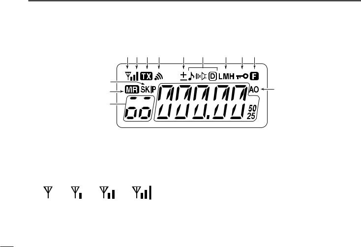
■ Function display
|
q wq eq rq tq y uq iq oq |
|
!4 |
!0 |
|
!3 |
||
|
!2 


 !1
!1
q BUSY INDICATOR
Appears when a signal is being received or the squelch is open.
Blinks while the monitor function is activated. (p. 19)
w SIGNAL INDICATOR
Shows receiving signal strength as below.
Weak RX Signal level Strong
Shows the output power level while transmitting.
e TRANSMIT INDICATOR (p. 19)
Appears during transmit.
r PAGER CALL INDICATOR (p. 46)
Blinks when a pager call is received. (This indicator appears only when an optional UT-108
is installed.)
t DUPLEX INDICATOR (p. 23)
“+” appears when plus duplex, “–” appears when minus duplex is selected.
|
|
|
|
|
|
|
|
|
|
|
|
|
|
|
|
|
|
|
|
|
|
|
|
|
|
|
|
|
|
|
|
|
|
|
|
|
|
|
|
|
|
Low |
Middle |
High |
|||||||||||
7
y TONE INDICATOR
“ ” appears while the subaudible tone encoder is in use. (p. 23)
“ ” appears while the tone (CTCSS) squelch function is in use. (p. 39)
“ ” appears while the tone (DTCS) squelch function is in use. (p. 39)
“
 ” appears with the “
 ” or “
 ” indicator while the pocket beep function (CTCSS or DTCS) is in use. (p. 41)
u OUTPUT POWER INDICATOR (p. 19)
“L” appears when the low output power is selected.
“M” appears when the middle output power is selected.
“H” appears when high output power is selected.
iKEY LOCK INDICATOR (p. 20)
Appears when the key lock function is ON.
o FUNCTION INDICATOR
Appears while a secondary function is being accessed.
!0AUTO POWER OFF INDICATOR (p. 52)
Appears while the auto power OFF function is activated.
!1FREQUENCY READOUT
Shows operating frequency, channel number or channel names, depending on display type (p. 20).
!2MEMORY CHANNEL INDICATOR (p. 26)
Shows the selected memory channel number.
“C” appears when the call channel is selected.
PANEL DESCRIPTION 2
!3MEMORY MODE INDICATOR (p. 26)
Appears while in memory mode or channel number indication mode.
!4SKIP CHANNEL INDICATOR (p. 37)
Appears when the selected memory channel is specified as a skip channel.
1
2
3
4
5
6
7
8
9
10
11
12
13
14
15
16
17
18
19
8
 3 BATTERY PACKS
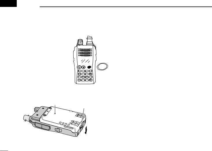
■ Battery pack replacement
q Before replacing the battery pack, push and hold [PWR] for 1 sec. to turn the power OFF.
|
|
|
PWR |
PWR |
A |
B |
C |
D |
|
FUNC |
CALL |
MR |
CLR |
|
TONE |
P.BEEP |
T.SCAN |
BANK |
|
1 |
2 |
3 |
|
|
DUP |
SCAN |
SKIP |
OPT |
|
4 |
5 |
6 |
0 |
|
PRIO |
SET |
H/M/L |
|
|
7 |
8 |
9 |
ENT |
|
wPush the battery release button in the direction of the arrow as shown below. The battery pack is then released.
Battery pack
Battery release button
D Battery packs
Battery |
Voltage |
Capacity |
Battery life*1 |
|
pack |
||||
|
|
|
||
BP-226 |
Battery case for AA |
—*2 |
||
(LR6)×5 alkaline |
||||
|
|
|||
BP-227 |
7.2 V |
1700 mAh |
7 hrs. |
|
|
|
|
|
|
*1 Operating periods are calculated under the following conditions; Tx : Rx : standby =1 : 1 : 8, power save function: auto setting is activated
*2 Operating period depends on the alkaline cells used.
9
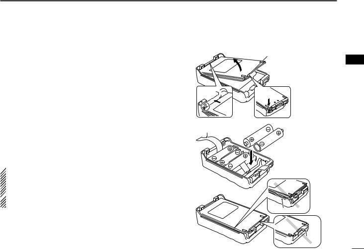
D Battery case— optional for some versions
When using a BP-226 attached to the transceiver, install 5 AA (LR6) size alkaline batteries as illustrated at right.
q Hook your finger under the latch, and open the cover in the direction of the arrow (q). (Fig.1)
wThen, install 5 × AA (LR6) size alkaline batteries. (Fig.2)
•Install the alkaline batteries only.
•Be sure to observe the correct polarity.
•Do not pin the ribbon under the batteries.
eClose the cover with fitting in the direction of the arrow (w) first, then firm the latch in place (e). (Fig.1)
•Be sure to the gasket and the ribbon are set correctly, and do not protrude out of the battery case. (Fig.3)
 R CAUTION!
• When installing batteries, make sure they are all the
same brand, type and capacity. Also, do not mix new and
old batteries together.
 • Keep battery contacts clean. It’s a good idea to clean battery terminals once a week.
BATTERY PACKS 3
Fig.1 |
BP-226 Latch |
w
 e
e
Fig.2
Ribbon
Fig.3
Gasket

 Ribbon
1
2
3
4
5
6
7
8
9
10
11
12
13
14
15
16
17
18
19
10

3 BATTERY PACKS
■ Cautions
Misuse of Lithium-Ion batteries may result in the following hazards: smoke, fire, or the battery may rupture. Misuse can also cause damage to the battery or degradation of battery performance.
•R DANGER! Use and charge only specified Icom battery packs with Icom radios. Only Icom battery packs are tested and approved for use with Icom radios. Using third-party or counterfeit battery packs may cause smoke, fire, or cause the battery to burst.
DBattery caution
•R DANGER! DO NOT hammer or otherwise impact the battery. Do not use the battery if it has been severely impacted or dropped, or if the battery has been subjected to heavy pressure. Battery damage may not be visible on the outside of the case. Even if the surface of the battery does not show cracks or any other damage, the cells inside the battery may rupture or catch fire.
•R DANGER! NEVER use or leave battery pack in areas with temperatures above +60˚C (+140˚F). High temperature build up in the battery, such as could occur near fires or stoves, inside a sun heated car, or in direct sunlight may cause the battery to rupture or catch fire. Excessive temperatures may also degrade battery performance or shorten battery life.
•R DANGER! DO NOT expose the battery to rain, snow, seawater, or any other liquids. Do not charge or use a wet battery. If the battery gets wet, be sure to wipe it dry before using.
•R DANGER! NEVER incinerate an used battery pack since internal battery gas may cause it to rupture, or may cause an explosion.
•R DANGER! NEVER solder the battery terminals, or NEVER modify the battery pack. This may cause heat generation, and the battery may burst, emit smoke or catch fire.
•R DANGER! Use the battery only with the transceiver for which it is specified. Never use a battery with any other equipment, or for any purpose that is not specified in this instruction manual.
•R DANGER! If fluid from inside the battery gets in your eyes, blindness can result. Rinse your eyes with clean water, without rubbing them, and see a doctor immediately.
•WARNING! Immediately stop using the battery if it emits an abnormal odor, heats up, or is discolored or deformed. If any of these conditions occur, contact your Icom dealer or distributor.
•WARNING! Immediately wash, using clean water, any part of the body that comes into contact with fluid from inside the battery.
11
 Loading...