


INSTRUCTION MANUAL
MULTIBAND FM TRANSCEIVER
iT81A/E
This device complies with Part 15 of the FCC rules. Operation is subject to the following two conditions: (1) This device may not cause harmful interference, and (2) this device must accept any interference received, including interference that may cause undesired operation.

IMPORTANT
READ ALL INSTRUCTIONS carefully and com-
pletely before using the transceiver.
SAVE THIS INSTRUCTION MANUAL—This in-
struction manual contains important operating instructions for the IC-T81A/E.
EXPLICIT DEFINITIONS
The explicit definitions below apply to this instruction manual.
WORD |
DEFINITION |
|
RWARNING |
Personal injury, fire hazard or electric |
|
shock may occur. |
||
CAUTION |
k. |
|
Equipment damage may occur. |
||
NOTE |
If disregarded, inconvenience only. No risk |
|
of personal injury, fire or electric shoc |
||
|
||
|
|
Versions of the IC-T81A/E which display the “CE” symbol on the serial number seal, comply with the European harmonised standard ETS300 684 (EMC product standard for Commercially Available Amateur Radio Equipment).
ii
CAUTIONS
RWARNING! NEVER hold the transceiver so that the antenna is very close to, or touching exposed parts of the body, especially the face or eyes, while transmitting. The transceiver will perform best if the microphone is 5 to 10 cm (2 to 4 in) away from the lips and the transceiver is vertical.
RWARNING! NEVER operate the transceiver with a headset or other audio accessories at high volume levels. Hearing experts advise against continuous high volume operation. If you experience a ringing in your ears, reduce the volume or discontinue use.
NEVER connect the transceiver to an AC outlet or to a power source of more than 16 V DC. Such a connection will damage the transceiver.
NEVER connect the transceiver to a power source that is DC fused at more than 5 A. Accidental reverse connection will be protected by this fuse, higher fuse values will not give any protection against such accidents and the transceiver will be ruined.
NEVER attempt to charge alkaline or dry cell batteries. Beware that external DC power connections will charge batteries inside the battery case. This will damage not only the battery case but also the transceiver.

DO NOT push the PTT when not actually desiring to transmit.
Place unit in a secure place to avoid inadvertent use by children.
DO NOT operate the transceiver near unshielded electrical blasting caps or in an explosive atmosphere.
AVOID using or placing the transceiver in direct sunlight or in areas with temperatures below –10°C (+14°F) or above +60°C (+140°F).
The use of non-Icom battery packs/chargers may impair transceiver performance and invalidate the warranty.
Even when the transceiver power is OFF, a slight current still flows in the circuits. Remove the battery pack or case from the transceiver when not using it for a long time. Otherwise, the battery pack or installed Ni-Cd batteries will become exhausted.
For USA only:
Caution: Changes or modifications to this transceiver, not expressly approved by Icom Inc., could void your authority to operate this transceiver under FCC regulations.
SUPPLIED ACCESSORIES |
|
Accessories included with the transceiver: |
|
Battery pack (BP-199 or BP-200) . . . . . . . . . . . . . . . . . |
1 |
Antenna . . . . . . . . . . . . . . . . . . . . . . . . . . . . . . . . . . . . . |
1 |
Handstrap . . . . . . . . . . . . . . . . . . . . . . . . . . . . . . . . . . . |
1 |
Belt clip . . . . . . . . . . . . . . . . . . . . . . . . . . . . . . . . . . . . . |
1 |
*Some versions are supplied with a wall charger.
q |
w |
e |
r |
iii

TABLE OF CONTENTS
IMPORTANT ................................................................................................... |
ii |
|
EXPLICIT DEFINITIONS ................................................................................ |
ii |
|
CAUTIONS ..................................................................................................... |
ii |
|
SUPPLIED ACCESSORIES ........................................................................... |
iii |
|
TABLE OF CONTENTS ................................................................................. |
iv |
|
1 |
ACCESSORY ATTACHMENT ................................................................... |
1 |
2 |
PANEL DESCRIPTION ......................................................................... |
2–5 |
|
■ Switches, controls, keys and connectors ............................................... |
2 |
|
■ Function display ..................................................................................... |
4 |
3 BATTERY PACKS AND CHARGING ................................................... |
6–8 |
|
|
■ Battery pack charging ............................................................................ |
6 |
|
■ Charging precautions ............................................................................. |
6 |
|
■ About battery packs ............................................................................... |
6 |
|
■ Charging connections ............................................................................ |
7 |
|
■ Battery case ........................................................................................... |
8 |
4 |
BASIC OPERATION ........................................................................... |
9–14 |
|
■ Power ON .............................................................................................. |
9 |
|
■ Setting a frequency ................................................................................ |
9 |
|
■ Setting tuning steps ............................................................................. |
10 |
|
■ Selecting a memory channel ................................................................ |
11 |
|
■ Lock function ........................................................................................ |
11 |
|
■ Receive and transmit ........................................................................... |
11 |
|
■ FM broadcast reception ....................................................................... |
12 |
|
■ Air band reception ................................................................................ |
12 |
|
■ Narrow FM operation ........................................................................... |
12 |
|
■ RIT/VXOa function ............................................................................... |
13 |
|
■ Receive mode ...................................................................................... |
14 |
5 |
REPEATER OPERATION ................................................................. |
15–17 |
|
■ General ................................................................................................ |
15 |
|
■ Subaudible tones for repeater use ....................................................... |
16 |
|
■ Setting an offset frequency .................................................................. |
16 |
|
■ Auto repeater function ......................................................................... |
17 |
6 |
MEMORY/CALL PROGRAMMING ................................................... |
18–20 |
|
■ General ................................................................................................ |
18 |
|
■ Programming a memory channel ......................................................... |
18 |
iv |
|
|
|
■ Memory editing .................................................................................... |
19 |
|
■ Memory names .................................................................................... |
20 |
7 |
DTMF MEMORY ..................................................................................... |
21 |
|
■ Programming a DTMF code ................................................................ |
21 |
|
■ Transmitting a DTMF code .................................................................. |
21 |
8 |
SCAN FUNCTIONS .......................................................................... |
22–24 |
|
■ Scan types ........................................................................................... |
22 |
|
■ Full/programmed scan ......................................................................... |
23 |
|
■ Memory (skip) scan ............................................................................. |
23 |
|
■ Skip channel setting ............................................................................. |
24 |
|
■ Scan resume condition ........................................................................ |
24 |
9 |
SUBAUDIBLE TONE OPERATION .................................................. |
25–26 |
|
■ Tone squelch ........................................................................................ |
25 |
|
■ Tone scan ............................................................................................ |
26 |
|
■ Pocket beep operation ......................................................................... |
26 |
10 OTHER FUNCTIONS ........................................................................ |
27–30 |
|
|
■ Help function ........................................................................................ |
27 |
|
■ Initial set mode ..................................................................................... |
27 |
|
■ Resetting the CPU ............................................................................... |
29 |
|
■ Cloning ................................................................................................. |
30 |
11 |
TROUBLESHOOTING ............................................................................ |
31 |
12 |
SPECIFICATIONS ................................................................................... |
32 |
13 |
OPTIONS ................................................................................................ |
33 |
14 MODE ARRANGEMENT .................................................................. |
34–35 |
|
15 CS-T81 CLONING SOFTWARE (OPTION) ...................................... |
36–39 |
|
|
■ Getting started ..................................................................................... |
36 |
|
■ System requirements ........................................................................... |
36 |
|
■ Software installation ............................................................................. |
36 |
|
■ COM port/Call sign setting ................................................................... |
37 |
|
■ Memory channel list description .......................................................... |
37 |
|
■ Edit menu ............................................................................................. |
38 |
|
■ DTMF autodial ..................................................................................... |
38 |
|
■ Common settings ................................................................................. |
39 |
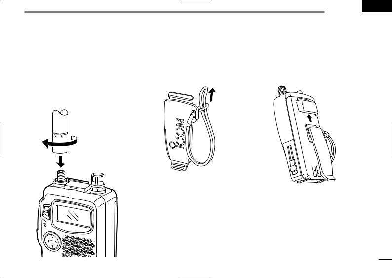
D Antenna
Screw the supplied antenna onto the antenna connector as shown in the diagram below.
Keep the jack cover attached when jacks are not in use to avoid bad contacts.
uCAUTION:
Transmitting without the an-
tenna may damage the transceiver.
ACCESSORY ATTACHMENT 1
D Handstrap |
D Belt clip |
Attach the handstrap to the belt clip, be- |
Attach the belt clip to the transceiver as |
fore attaching the belt clip to the trans- |
illustrated below. |
ceiver, as below. |
|
1
2 |
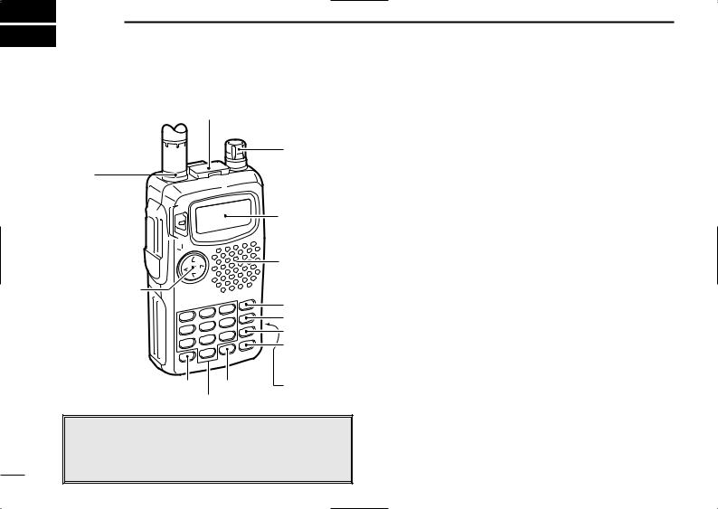
PANEL DESCRIPTION |
|
■ Switches, controls, keys and connectors |
||
|
u [SP/MIC] |
q MULTIFUNCTION SWITCH [MULTI] |
|
|
Push to select the tone or duplex menu. (pgs. 15–17); |
|
i [DIAL] |
push for 1 sec. to enter set mode (p. 35). |
|
Push to increase/decrease the volume (p. 11). |
|
|
|
|
y |
|
Push to change the operating band; push for 1 sec. |
|
|
to start a scan (p. 22). |
t [PWR]  r [PTT]
e [TX/RX]  w [SQL]
q [MULTI]
!5[M]
Function display
Speaker/
Microphone
o [VFO] |
!0[MR] |
!1[CALL] |
!2[H/L] |
!3[RIT] !6[DC13.5V]
!4
NOTE: In this manual—
Push [MULTI] means push ñ directly;
Push [MULTI( )] means push ñ up or down; and
Push [MULTI( )] means push ñ left or right. See q
2
w SQUELCH SWITCH [SQL] (p. 11)
Push and hold to open the squelch.
While pushing, rotate [DIAL] to adjust the squelch setting.
e TX/RX INDICATOR (p. 11)
Lights red while transmitting; green while receiving (or when the squelch is open).
r PTT SWITCH [PTT] (p. 11)
Push and hold to transmit; release to receive.
t POWER SWITCH [PWR] (p. 9)
Push for 1 sec. to turn power on and off.
y ANTENNA CONNECTOR (p. 1)
Connects the supplied antenna.
u EXTERNAL SPEAKER AND MICROPHONE JACKS [SP/MIC]
Connect an optional speaker-microphone or headset, if desired. The internal microphone and speaker will not function when either is connected. (See p. 33 for options.)
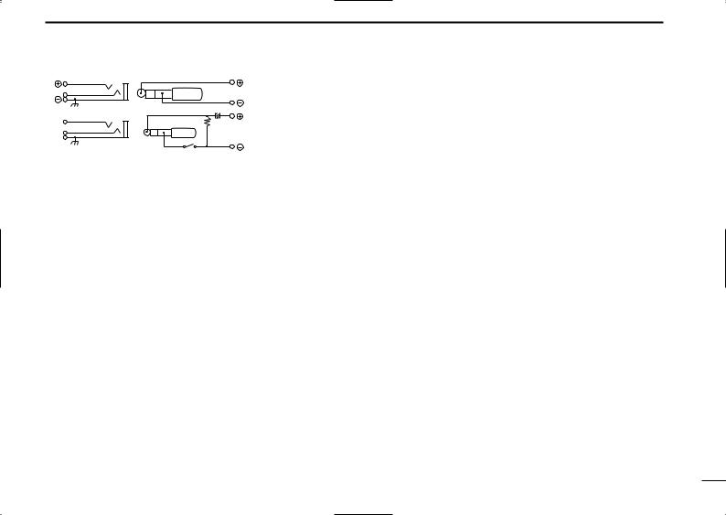
Remote [SP] |
|
Audio out |
This connection |
|
|
(8 Ω) |
does not apply |
|
|
|
when a conden- |
MIC |
33 kΩ |
Audio input |
sor microphone |
[MIC] |
|
|
|
|
(2 kΩ) |
is connected. |
|
3.2 V |
|
PTT
PTT
NOTE: When connecting or disconnecting an external speaker-microphone, first turn off power to the transceiver.
i TUNING CONTROL [DIAL]
Changes the operating frequency; memory channel in memory mode; set mode contents in set mode, etc.
o VFO/CLEAR KEY [VFO(CLR/MHz)Å]
Push to select VFO mode. (p. 9)
Cancels some functions such as digit input before entry, scans, etc.
Push and hold for 1 sec., then rotate [DIAL] to change the MHz digit. (p. 10)
While pushing [PTT], this key sends a DTMF “A.” (p. 21)
!0MEMORY MODE KEY [MR(MW)ı]
Push to select memory mode. (p. 11)
•“X” appears while in memory mode.
Push for 1 sec. to enter memory write mode. (p. 18)
While pushing [PTT], this key sends a DTMF “B.” (p. 21)
!1CALL KEY [CALLÇ]
Push to select the call channel. (p. 19)
While pushing [PTT], this key sends a DTMF “C.” (p. 21)
PANEL DESCRIPTION 2
!2OUTPUT POWER KEY [H/L(LOCK)Î]
Push to toggle between low and high power. (p. 11)
•“LOW” appears while low power is selected.
Push for 1 sec. to toggle the lock function on/off. (p. 11)
•“L” appears while the lock function is activated.
While pushing [PTT], this key sends a DTMF “D.” (p. 21)
!3RIT KEY [RIT(TSCAN)#] (p. 13)
Push, then rotate [DIAL] to change the RIT/VXO setting.
•This function is only available for the 1.2 GHz band and RIT or VXO must be activated in set mode (p. 13).
Push for 1 sec. to turn the tone scan function on/off. (p. 26)
While pushing [PTT], this key sends a DTMF “F.” (p. 21)
!4DIGIT KEYS
Input the specified digit during frequency input, memory channel selection, etc.
Transmit the DTMF code of the specified digit while pushing [PTT]. (p. 21)
!5MHz KEY [• (M)]
Used as a shortcut for inputting frequencies. (p. 10)
Transmits an “E” for DTMF operation while pushing [PTT]. (p. 21)
!6EXTERNAL DC POWER JACK [DC13.5V] |
|
Allows you to operate the transceiver with a 4.5 to 16 V DC |
|
power source using optional cables, CP-12L or OPC-254L. |
|
u CAUTION: DO NOT connect when a battery case is at- |
|
tached. |
3 |
|
2 PANEL DESCRIPTION
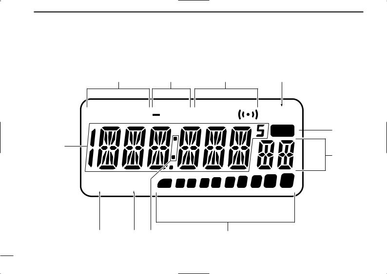
■ Function display
w |
e |
r |
t |
W FM AM DUP T SQL |
SKIP |
MR 

q
VOL LOW 1 |
5 |
9 |
y
u
!1 |
!0 o |
i |
4

q FREQUENCY INDICATION
Shows the selected frequency, set mode contents, etc.
w MODE INDICATORS
Indicate the operating mode.
e DUPLEX INDICATOR (p. 15)
Appears during semi-duplex operation.
•“–DUP” appears for minus duplex; “DUP” appears for plus duplex.
r TONE INDICATORS
“T” appears when the subaudible tone encoder (p. 15) is in use; “T SQLS” appears during pocket beep operation (p. 26) and “T SQL” appears when the tone squelch function (p. 25) is activated.
t SKIP INDICATOR (p. 23)
Appears when the selected channel is set as a “skip” channel.
y MEMORY MODE INDICATOR (p. 11) Appears while in memory mode.
u MEMORY CHANNEL INDICATOR
Indicates the selected memory channel and other items such as the call channel, set mode items, etc.
i S/RF INDICATORS (p. 11)
Show the relative signal strength while receiving and the output power selection while transmitting.
PANEL DESCRIPTION 2
o RIT/VXO INDICATOR (p. 13)
Appears when either the RIT or VXO function is activated and the 1.2 GHz band is selected.
!0LOW POWER INDICATOR (p. 11) Appears when low output power is set.
!1VOLUME INDICATOR
Appears while adjusting the volume.
•Indicators also appear in place of the operating frequency while adjusting volume to visually indicate the selected volume level.
5

 3 BATTERY PACKS AND CHARGING
■ Battery pack charging
The supplied* BP-198, BP-199 or BP-200 BATTERY PACK includes rechargeable Ni-MH batteries and can be charged approx. 300 times. Charge the battery pack before first operating the transceiver or when the battery pack becomes exhausted.
*Optional for versions which come with the BP-197 BATTERY CASE.
If you want to get the longest life out of your battery pack (300+ charges), the following points should be observed:
1.Avoid overcharging. The charging period should be less than 15 hours.
2.Use the battery until it becomes completely exhausted under normal conditions. We recommend battery charging just after transmitting becomes impossible.
■ Charging precautions
NEVER attempt to charge alkaline batteries. This will cause internal liquid leakage and damage the battery case and transceiver.
NEVER connect two or more chargers at the same time.
Charging may not occur under temperatures of 10°C (50°F) or over temperatures of 40°C (104°F).
■ About battery packs
D Operating period
Depending on attached battery pack, the operating period of the transceiver varies. When the approx. voltage of battery packs BP-198, BP-199 or BP-200 falls to 4, 5 or 8 V, respectively, charging is necessary. Refer to p. 33 for operating period details.
D Battery life
If your battery pack seems to have no capacity even after being fully charged, completely discharge it by leaving the power ON overnight. Then fully charge the battery pack again.
If the battery pack still does not retain a charge (or very little), a new battery pack must be purchased.
NOTE: When using a battery pack for the first time or after long periods of inactivity between charges (approx. 2 months or more), the battery pack will not be able to retain a full charge immediately. Subsequent charge/discharge cycles will eventually bring the battery pack up to full charge capacity.
6
■ Charging connections
D Regular charging |
|
|
Attach the sup- |
|
|
plied or optional |
Charging period: |
|
battery pack; |
||
15 hours |
||
then, connect the |
|
|
supplied* wall |
|
|
charger via an AC |
|
|
outlet as shown at |
Wall charger |
|
right. |
To |
|
*Optional for ver- |
||
[DC13.5V] |
||
sions which include |
|
a battery case.
D Rapid charging with the BC-119
Fix the optional AD-88 TERMINAL PC BOARD FOR CHARGER into the BC-119 with the 4 supplied screws.
Insert the optional AD-87A CHARGE ADAPTER into the charging slot of the BC-119.
Insert the optional AD-87B CHARGE ADAPTER into AD-87A (check orientation).
Insert the battery pack, either by itself or attached to the transceiver, into the whole assembly for charging (see right).
BATTERY PACKS AND CHARGING 3
Charging periods: 1 hour (w/BP-198 or BP-199) 1.5 hours (w/BP-200)
Check orientation |
AD-87B |
|
(optional) |
||
for correct charging |
||
|
AD-87A (optional)
AD-88 (optional)
BC-119 (optional)
7

3 BATTERY PACKS AND CHARGING
D Operation with an optional cable
Connect an optional charger or cable to the transceiver as illustrated below. Be careful of battery overcharging as the connected battery is charged simultaneously.
u CAUTION: When the BP-197 BATTERY CASE is connected, charging cannot take place.
Wall charger
|
CP-12L |
|
(optional) |
|
black |
To |
|
[DC13.5V] |
|
OPC-254L |
white |
(optional) |
*To charge the battery pack
13 to 16 V DC is necessary.
■ Battery case
When using a battery case attached to the transceiver, install 3 AA(R6) size alkaline batteries as illustrated below.
Remove the case from the transceiver.
Open the case.
Install 3 AA(R6) size alkaline

 batteries into the battery case.
8
 Loading...