


INSTRUCTION MANUAL
COMMUNICATIONS RECEIVER
iR75
IMPORTANT
READ THIS INSTRUCTION MANUAL CAREFULLY before attempting to operate the receiver.
SAVE THIS INSTRUCTION MANUAL. This manual contains important safety and operating instructions for the IC-R75.
EXPLICIT DEFINITIONS
WORD |
DEFINITION |
|
RWARNING |
Personal injury, fire hazard or electric |
|
|
shock may occur. |
|
CAUTION |
Equipment damage may occur. |
|
|
If disregarded, inconvenience only. |
|
NOTE |
||
No risk of personal injury, fire or |
||
|
electric shock. |
PRECAUTIONS
RNEVER apply AC to the [DC13.8V] jack on the receiver rear panel. This could cause a fire or ruin the receiver.
RNEVER apply more than 16 V DC, such as a 24 V battery, to the [DC13.8V] jack on the receiver rear panel. This could cause a fire or ruin the receiver.
RNEVER let metal, wire or other objects touch any internal part or connectors on the rear panel of the receiver. This may result in an electric shock.
NEVER expose the receiver to rain, snow or any liquids.
AVOID using or placing the receiver in areas with temperatures below –10°C (+14°F) or above +60°C (+140°F). Be aware that temperatures on a vehicle’s dashboard can exceed 80°C (+176°F), resulting in permanent damage to the receiver if left there for extended periods.
AVOID placing the receiver in excessively dusty environments or in direct sunlight.
AVOID placing the receiver against walls or putting anything on top of the receiver. This will obstruct heat dissipation.
Place unit in a secure place to avoid inadvertent use by children.
During mobile operation, DO NOT operate the receiver without running the vehicle’s engine. When receiver power is ON and your vehicle’s engine is OFF, the vehicle’s battery will soon become exhausted.
Make sure the receiver power is OFF before starting the vehicle. This will avoid possible damage to the receiver by ignition voltage spikes.
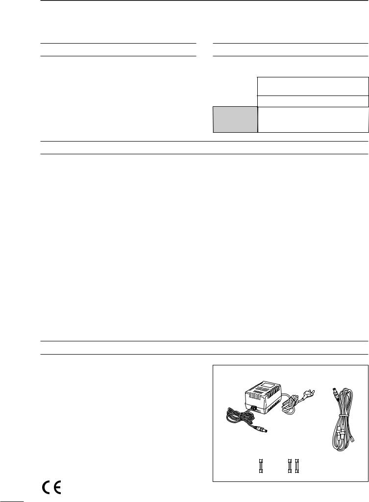
SUPPLIED ACCESSORIES
The receiver comes with the following accessories. |
|
|
||
q AC adapter (AD-55/A/V)* |
Qty. |
q |
w |
|
1 |
|
|
||
w DC power cable (OPC-869)* ............................... |
1 |
|
|
|
e Fuse (FGB 3 |
A; internal use) ............................... |
1 |
|
|
r Fuse (FGB 3 |
A; for DC cable)* ............................ |
2 |
|
|
* Either AC adapter + 1 fuse (q, e) or DC power cable + 3 fuses (w, e, r) are supplied depending on versions.
e r
Versions of the IC-R75 which display the “CE” symbol on the serial number seal comply with the European harmonised standard ETS300 684 (EMC product standard for Commercially Available Amateur Radio Equipment).
i

TABLE OF CONTENTS 1
IMPORTANT .............................................................. |
i |
EXPLICIT DEFINITIONS ........................................... |
i |
PRECAUTIONS ......................................................... |
i |
SUPPLIED ACCESSORIES ...................................... |
i |
1 TABLE OF CONTENTS ....................................... |
1 |
2 PANEL DESCRIPTION ................................... |
2 – 6 |
■Front panel ........................................................ |
2 |
■Function display ................................................. |
5 |
■Rear panel ......................................................... |
6 |
3 INSTALLATION AND CONNECTIONS ......... |
7 – 10 |
■Grounding .......................................................... |
7 |
■Receiver stand ................................................... |
7 |
■Optional bracket and carrying handle ................ |
7 |
■Connections ...................................................... |
8 |
■Antenna connection ........................................... |
9 |
■Tape recorder connections ................................ |
9 |
■Transceive function ............................................ |
9 |
■FSK and AFSK (SSTV) connections ............... |
10 |
■Connecting to a PC ......................................... |
10 |
4 FREQUENCY SETTING .............................. |
11 – 13 |
■Read me first ................................................... |
11 |
■Using the keypad ............................................. |
11 |
■Frequency setting ............................................ |
12 |
■Dial lock function ............................................. |
13 |
5 RECEIVE FUNCTIONS ............................... |
14 – 20 |
■Mode selection ................................................ |
14 |
■Squelch and RF gain ....................................... |
14 |
■Twin PBT operation ......................................... |
15 |
■Noise blanker ................................................... |
15 |
■Preamp ............................................................ |
16 |
■Attenuator ........................................................ |
16 |
■AGC time constant .......................................... |
16 |
■Antenna selection ............................................ |
16 |
■CW reverse mode ............................................ |
17 |
■CW pitch control .............................................. |
17 |
■RTTY reverse mode ........................................ |
17 |
■Filter selection ................................................. |
18 |
■Filter set mode ................................................. |
19 |
■Optional noise reduction function .................... |
20 |
■Optional auto notch function ............................ |
20 |
6 MEMORY OPERATION ............................... |
21 – 24 |
■Memory channels ............................................ |
21 |
■Memory channel selection ............................... |
21 |
■Memory channel programming ........................ |
22 |
■Frequency transferring .................................... |
23 |
■Memory names ................................................ |
24 |
■Memory clearing .............................................. |
24 |
7 SCANS ........................................................ |
25 – 27 |
■Scan types ....................................................... |
25 |
■Preparation ...................................................... |
25 |
■Programmed scan operation ........................... |
26 |
■Memory/select memory scan operation .......... |
26 |
■Setting select memory channels ..................... |
26 |
■Priority watch operation ................................... |
27 |
■Auto memory write scan operation .................. |
27 |
8 CLOCK AND TIMERS ................................. |
28 – 29 |
■Setting the current time ................................... |
28 |
■Setting power-on time ...................................... |
28 |
■Setting power-off time ...................................... |
29 |
■Setting sleep timer period ................................ |
29 |
9 SET MODE .................................................. |
30 – 33 |
■Set mode description ....................................... |
30 |
10 OPTION INSTALLATIONS ....................... |
34 – 35 |
■Opening the receiver’s case ............................ |
34 |
■CR-282 HIGH STABILITY CRYSTAL UNIT .......... |
34 |
■UT-102 VOICE SYNTHESIZER UNIT .................. |
34 |
■UT-106 DSP UNIT ............................................. |
35 |
■Optional IF filters ............................................. |
35 |
11 MAINTENANCE ........................................ |
36 – 37 |
■Troubleshooting ............................................... |
36 |
■Resetting the CPU ........................................... |
36 |
■Fuse replacement ............................................ |
37 |
■Clock backup battery replacement .................. |
37 |
12 SPECIFICATIONS ........................................... |
38 |
13 OPTIONS ......................................................... |
39 |
14 CONTROL COMMAND ............................ |
40 – 43 |
■Remote jack (CI-V) information ....................... |
40 |
1
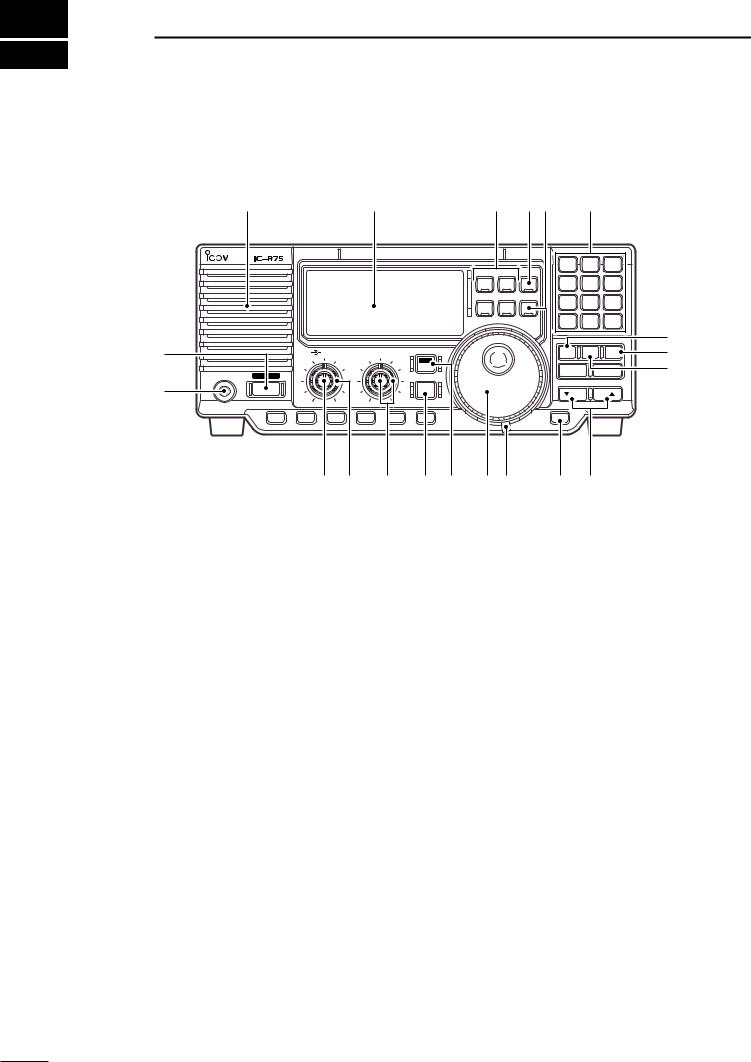
2 PANEL DESCRIPTION
■ Front panel
Speaker |
Function display (p. 5) |
!8 |
!7!6 |
!5 |
|
||||||
|
|
|
|
|
|
|
|
||||
|
|
|
|
|
COMMUNICATIONS RECEIVER |
|
|
|
|
|
|
|
|
|
|
|
|
|
|
1 |
ABC2 |
DEF 3 |
|
|
|
|
|
|
|
|
SSB CW/RTTY FIL |
|
|
|
|
|
|
|
|
|
|
|
|
GHI 4 |
JKL 5 |
MNO6 |
|
|
|
|
|
|
|
|
AM FM |
TS |
TUV 8 |
WXY9 |
|
|
|
|
|
|
|
|
|
PRS 7 |
|
||
|
|
|
|
|
|
|
|
. |
QZ 0 |
ENT |
|
|
|
|
|
|
|
|
|
|
|
|
!4 |
q |
|
AF |
RF/SQL |
TWIN PBT |
ANT |
|
V/M |
MW |
CLR |
!3 |
|
|
|
|
|
|
|
|
|
|
|
!2 |
|
|
|
|
|
|
|
SET |
|
SEL |
|
SCAN |
|
PHONES |
POWER |
|
|
|
|
|
|
|
|||
|
|
|
|
|
|
|
|
|
|
||
w |
|
|
|
|
|
CLOCK |
|
DN |
|
|
|
|
P.AMP |
ATT |
NR |
ANF |
NB |
AGC |
|
LOCK |
|
|
|
|
|
|
e r |
|
t |
y u |
i o |
!0 |
!1 |
|
|
qPOWER SWITCH [POWER]
Push momentarily to turn power ON.
•Turn the optional DC power supply ON in advance.
Push for 2 sec. to turn power OFF.
wHEADPHONE JACK [PHONES] (p. 8) Accepts headphones.
•When headphones are connected, the internal speaker or connected external speaker does not function.
eAF CONTROL [AF] (inner control)
Varies the audio output level from the speaker.
rRF GAIN/SQUELCH CONTROL [RF/SQL]
(outer control; pgs. 14, 30)
Adjusts the squelch threshold level. The squelch removes noise output from the speaker (closed condition) when no signal is received.
•The squelch is particularly effective for FM. It is also available for other modes.
•The control can be set as the squelch plus RF gain controls or squelch control only (RF gain is fixed at maximum) in set mode.
tPASSBAND TUNING CONTROLS [TWIN PBT]
(p. 15)
Adjust the receiver’s “passband width” of the 455 kHz and 9 kHz IF filters for the inner and outer controls, respectively.
• Set to the center positions when not in use.
yCLOCK MODE SWITCH [CLOCK] (p. 28)
Toggles between frequency indication and clock indication when pushed.
uANTENNA SELECTOR/SET MODE SWITCH [ANT/SET] (pgs. 16, 30)
While in a frequency indication, enters set mode when pushed.
While in a frequency indication, toggles between the antenna 1 and 2 connectors when pushed for 2 sec.
While in the clock indication, enters time setting condition when pushed for 2 sec.
While in a timer indication, toggles the timer ON or OFF when pushed.
iTUNING DIAL
Changes the displayed frequency, selects set mode items, etc.
oTUNING DIAL TENSION LATCH
Adjusts the tension of the tuning dial.
!0LOCK/SPEECH SWITCH [LOCK] (pgs. 13, 34)
Toggles the frequency lock function ON and OFF.
Announces the selected readout frequency when an optional UT-102 is installed and when pushed for 2 sec.
2

!1MEMORY CHANNEL UP/DOWN SWITCHES
[√DN]/[UP ∫] (p. 21)
Select a memory channel.
Select a set mode contents while in set mode.
Select a timer or time indication while in clock indication.
Select a filter set mode contents while in filter set mode.
!2MEMORY WRITE SWITCH [MW] (pgs. 22, 27)
Stores the displayed frequency and operating mode into the selected memory channel when pushed for 2 sec.
Toggles the programmed scan and auto memory write scan when pushed.
!3CLEAR SWITCH [CLR] (p. 24)
Clears the input digits while inputting a frequency or memory channel number.
Clears the selected memory channel contents when pushed for 2 sec. in memory mode.
•This switch does not function in VFO mode.
!4VFO/MEMORY SWITCH [V/M] (pgs. 21, 23)
Toggles the operating mode between VFO mode and memory mode when pushed.
Selects a memory channel for inputting a memory channel number when pushed.
Transfers the memory contents to VFO when pushed for 2 sec.
!5KEYPAD (pgs. 11, 21)
The keypad can be used for several functions as below:
•Keypad then [ENT]
—Direct frequency input.
•Keypad then [V/M]
—Memory channel selection.
•[ENT] then keypad in memory name indication mode
—Alphanumeric input for memory name, etc.
!6QUICK TUNING STEP SWITCH [TS] (pgs. 12, 13)
Selects a quick tuning step or turns the quick tuning step OFF.
•While the quick tuning indicator (") is displayed, the frequency can be changed in kHz or MHz steps.
While the quick tuning step is OFF, turns the 1 Hz step ON and OFF when pushed for 2 sec.
•1 Hz indication appears and the frequency can be changed in 1 Hz steps.
While the kHz quick tuning step is selected, enters tuning step set mode when pushed for 2 sec.
While the memory name indication is selected in memory mode, pushing this switch shows the operating frequency; and rotating the tuning dial while pushing this switch changes the frequency temporally.
PANEL DESCRIPTION 2
!7FILTER SWITCH [FIL] (pgs. 18, 19)
Push momentarily to toggle between the pre-pro- grammed normal, wide and narrow IF filters for the selected operating mode.
Push for 2 sec. to enter filter set mode.
!8MODE SWITCHES [SSB]/[CW/RTTY]/[AM]/[FM]
(p. 14)
Select an operating mode.
•Push [SSB] to toggle between LSB and USB.
•Push [CW/RTTY] to toggle between CW and RTTY.
•Push [CW/RTTY] for 2 sec. to toggle between CW and CW reverse or RTTY and RTTY reverse.
•Push [AM] to toggle between AM and S-AM.
•Push [FM] to select FM.
3
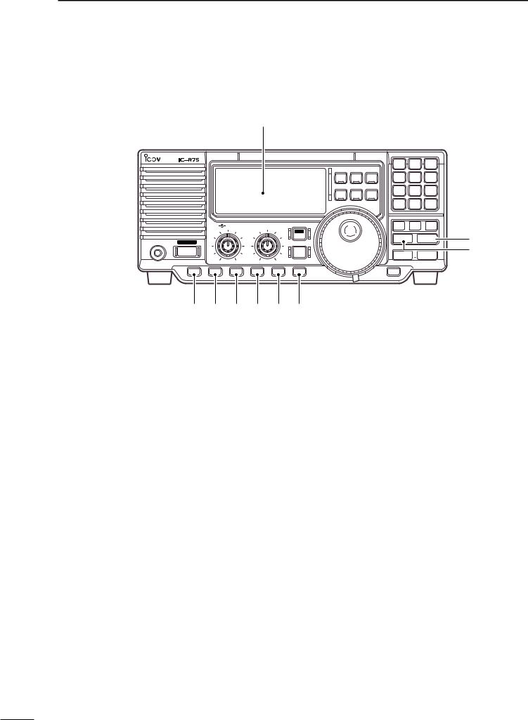
2 PANEL DESCRIPTION
■ Front panel (continued)
Function display (p. 5)
PHONES POWER
P.AMP |
!9
|
|
|
COMMUNICATIONS RECEIVER |
|
|
|
|
|
|
|
|
|
SSB CW/RTTY FIL |
||
|
|
|
|
|
AM |
FM |
TS |
AF |
RF/SQL |
TWIN PBT |
|
|
|
|
|
|
|
|
|
ANT |
|
|
|
|
|
|
|
SET |
|
|
|
|
|
|
|
CLOCK |
|
|
|
ATT |
NR |
ANF |
NB |
AGC |
|
|
|
@0 |
@1 |
@2 |
@3 |
@4 |
|
|
|
1 |
ABC2 |
DEF 3 |
GHI 4 |
JKL 5 |
MNO6 |
PRS 7 |
TUV 8 |
WXY9 |
. |
QZ 0 |
ENT |
V/M  MW
MW  CLR
CLR
SEL  SCAN
SCAN
 DN
DN  UP
UP
LOCK
@6
@5
!9PREAMP SWITCH [P.AMP] (p. 16)
Push to toggle between preamp-1 and preamp-2 or turn the preamp OFF.
@0ATTENUATOR SWITCH [ATT] (p. 16)
Push to toggle the 20 dB attenuator function ON and OFF.
@1NOISE REDUCTION SWITCH [NR] (p. 20)
Toggles the optional noise reduction function ON and OFF when pushed. Functions in SSB, CW and RTTY modes. An optional UT-106 DSP UNIT is required.
Enters noise reduction level set mode when pushed for 2 sec. An optional UT-106 DSP UNIT is required.
@2AUTOMATIC NOTCH FILTER SWITCH
(p. 20)
Push to turn the optional automatic notch filter for receiving AM signals ON and OFF. An optional UT-106 is required.
@3NOISE BLANKER SWITCH [NB] (p. 15)
Toggles the noise blanker ON and OFF. The noise blanker reduces pulse-type noise such as that generated by automobile ignition systems. This function is not effective for FM, or non pulse-type noise.
@4AGC SWITCH [AGC] (p. 16)
Toggles the AGC (Automatic Gain Control) time constant fast and slow when pushed.
Toggles the AGC function ON and OFF when pushed for 2 sec.
@5SELECT SWITCH [SEL] (pgs. 24, 26)
Toggles the select memory setting ON and OFF when pushed in memory mode.
Toggles the memory name indication ON and OFF when pushed for 2 sec. in memory mode.
@6SCAN SWITCH [SCAN] (p. 25)
Push momentarily to start/stop the programmed scan in VFO mode.
Push momentarily to start/stop the memory scan in memory mode.
Push for 2 sec. to start the priority watch in VFO mode.
•Push [SCAN] again to cancel the priority watch.
4
PANEL DESCRIPTION 2
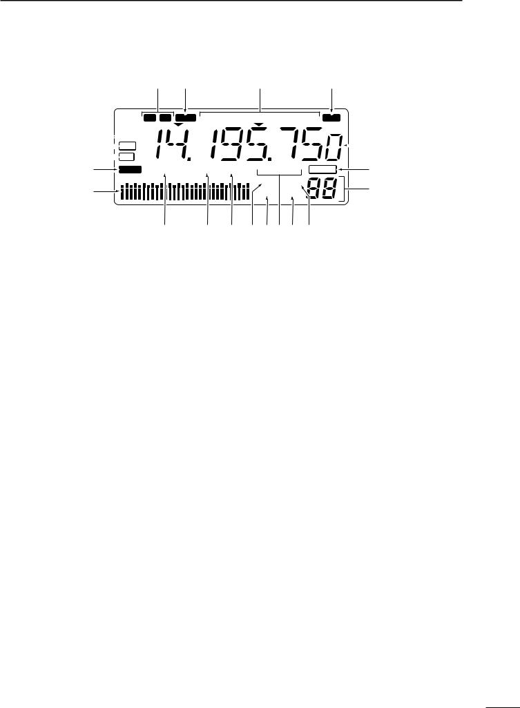
■ Function display
q

TIMER
w DSP e
DSP e ANF r
ANF r NR
NR
@1 |
@0 |
!9 |
!8 |
W N |
REV |
LSBUSBCW S-AMFMRTTY |
|
 !7
!7
t |
LOCK |
|
PREAMP 1 2 |
|
ATT |
ANT 1 2 |
F.AGC OFF |
BLANK |
!6 |
|
|
S1 |
3 |
7 |
9 |
|
|
60dB |
B VFO |
|
|
y |
|
|
|
|
|
|
|
|
!5 |
|
|
|
|
|
|
|
|
|
S |
||
|
|
|
|
|
|
|
|
|
||
|
|
|
|
|
|
|
|
|
|
|
|
|
|
u |
|
i |
o |
!0 !1 !2 !3 !4 |
|
||
qTIMER INDICATOR (p. 28)
Appears when power on/off timer or sleep timer is in use.
wDSP UNIT INDICATOR (p. 35)
Appears when an optional UT-106 DSP UNIT is installed.
eAUTOMATIC NOTCH FILTER INDICATOR (p. 20) Appears when the optional automatic notch filter is in use.
rNOISE REDUCTION INDICATOR (p. 20)
Appears when the optional noise reduction function is in use.
tLOCK INDICATOR (p. 13)
Appears when the dial lock function is in use.
ySIGNAL METER
Shows the relative receive signal strength.
Shows the S-meter squelch level when used.
uPREAMP INDICATOR (p. 16)
Appears when antenna preamp-1 or preamp-2 is in use.
iATTENUATOR INDICATOR (p. 16)
Appears when the attenuator function is in use.
oANTENNA INDICATORS (p. 16)
Indicate which antenna connector is in use.
!0NOISE BLANKER INDICATOR (p. 15)
Appears when the noise blanker function is in use.
!1SCAN INDICATOR (p. 25)
Appears when scan or priority watch is activated.
Flashes when scan or priority watch is paused.
!2AGC INDICATORS (p. 16)
“AGC” appears when slow AGC time constant is selected.
“F.AGC” appears when fast AGC time constant is selected.
“AGC OFF” appears when the AGC function is turned OFF.
“F.AGC” blinks while scanning or while using band scope via an optional RS-R75.
!3MEMORY MODE INDICATOR (p. 21)
Indicates memory mode is selected.
!4VFO MODE INDICATOR
Indicates VFO mode is selected.
!5MEMORY CHANNEL NUMBER READOUT
(p. 21)
Shows the selected memory channel number.
“S” appears when the displayed memory channel is designated as a select memory channel.
!6BLANK MEMORY INDICATOR
Shows that the displayed memory channel is not programmed.
• This indicator appears both in VFO and memory modes.
!7FREQUENCY READOUT
Shows the operating frequency.
!8RECEIVE INDICATOR
Appears while receiving a signal or when the squelch is open.
!9MODE INDICATORS (p. 14)
Indicate the selected operating mode.
@0REVERSE MODE INDICATOR (p. 17) Indicates a reverse operating mode is selected.
@1WIDE/NARROW FILTER INDICATORS (p. 18)
“ç” appears when the wide IF filter is selected.
“ã” appears when the narrow IF filter is selected.
5
2 PANEL DESCRIPTION
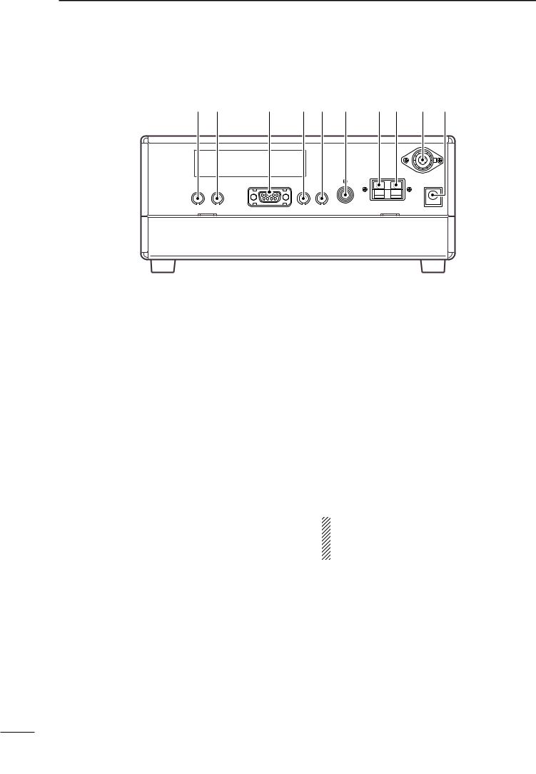
■ Rear panel
q w |
e r t y u i o !0 |
qRECORDER REMOTE JACK [REC REMOTE]
Controls the running of a tape recorder for recording. Connects to the REMOTE jack on a tape recorder.
• This function can be turned OFF in set mode. (p. 32)
wRECORDER JACK [REC]
Outputs receive audio signals. Connects to the AUX or LINE IN jack on a tape recorder.
eRS-232C CONNECTOR [RS-232C]
Connects an RS-232C cable. An RS-232C cable can be used to connect the receiver to a PC. In this way commands can be sent to the receiver via the PC.
rCI-V REMOTE CONTROL JACK [REMOTE]
Allows connection to an Icom CI-V system transceiver or another receiver for the transceive function. Also connects to a PC with several receivers for command control via an optional CT-17 CI-V
LEVEL CONVERTER.
tEXTERNAL SPEAKER JACK [EXT SP]
Connects an 8 Ω external speaker, if desired.
•When an external speaker is connected, the internal speaker does not function.
yMUTE CONTROL JACK [MUTE]
Mutes audio outputs and attenuates the receive signal input when grounded. Used for CI-V transceive operation with a transceiver.
uGROUND TERMINAL [GND] (p. 7) Connects the black terminal to ground.
i ANTENNA 2 TERMINAL [ANT 2] (p. 9)
Connects the red terminal to a 500 Ω long wire antenna.
oANTENNA 1 CONNECTOR [ANT 1] (p. 9) Connects a 50 Ω antenna with a PL-259 connector and a 50 Ω coaxial cable.
!0DC POWER JACK [DC 13.8V] (p. 8)
Connects the supplied AC adapter for versions with an AC adapter.
Connects to a 13.8 V DC power source using the supplied DC cable for versions without an AC adapter.
•Current of 1.5 A or greater is required.
DO NOT use a cigarette lighter socket as a power source when operating in a vehicle. The plug may cause voltage drops and ignition noise may be superimposed onto received audio.
6
INSTALLATION AND CONNECTIONS 3
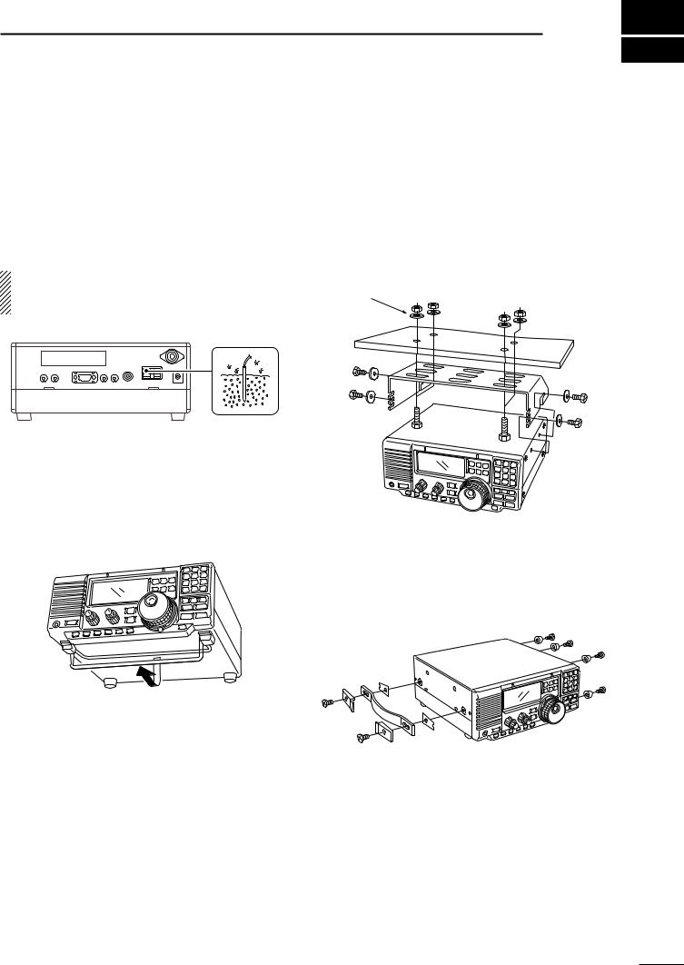
■ Grounding
To prevent accidents involving electricity and interference from transceivers, ground the receiver through the [GND] terminal on the rear panel.
For best results, connect a heavy gauge wire or strap to a long earth-sunk copper rod. Make the distance between the [GND] terminal and ground as short as possible.
RWARNING: NEVER connect the [GND] terminal to a gas or electric pipe, since the connection could cause an explosion or electric shock.
■Optional bracket and carrying handle
DMounting bracket
An optional IC-MB5 MOBILE MOUNTING BRACKET is available to install the radio under a table, on a wall, in a vehicle, etc.
Select an area to mount the receiver keeping in mind that the weight of the receiver is approx. 3 kg.
Flat washer
■ Receiver stand
The base of the receiver has an adjustable stand for desktop use. Set the stand to one of two angles depending on your operating conditions.
DCarrying handle
An optional handle allows you to easily carry and transport the receiver.
Attach the MB-23 CARRYING HANDLE with the supplied rubber feet as shown.
7

3 INSTALLATION AND CONNECTIONS
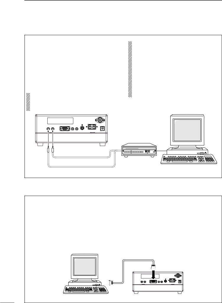
■ Connections
HEADPHONES
|
|
|
|
|
COMMUNICATIONS RECEIVER |
|
|
|
|
|
|
|
|
|
SSB |
CW/RTTY |
FIL |
|
|
|
|
|
|
AM |
FM |
TS |
|
|
AF |
RF/SQL |
TWIN PBT |
|
|
|
|
|
|
|
|
|
|
ANT |
|
|
|
|
|
|
|
|
SET |
|
|
PHONES |
POWER |
|
|
|
|
|
|
|
|
|
|
|
|
|
CLOCK |
|
|
|
P.AMP |
ATT |
NR |
ANF |
NB |
AGC |
|
|
1 |
ABC2 |
DEF 3 |
z 4 |
JKL 5 |
MNO6 |
PRS 7 |
TUV 8 |
WXY9 |
. |
z 0 |
ENT |
V/M  MW
MW  CLR
CLR
SEL  SCAN
SCAN
 DN
DN  UP
UP
LOCK
REMOTE (p. 9, 32) |
ANTENNA 2 |
ANTENNA 1 (p. 9) |
|||||||||||||||||||||||
Used for computer control and transceive. |
Connect a long wire |
Connect a Yagi antenna; |
|||||||||||||||||||||||
|
|
|
|
|
|
|
|
|
|
|
|
|
|
|
|
|
|
|
|
|
|
|
antenna; impedance: 500 Ω . |
impedance: 50 Ω . |
|
|
|
|
|
|
|
|
|
|
|
|
|
|
|
|
|
|
|
|
|
|
|
|
|
|
|
|
|
|
|
|
|
|
|
|
|
|
|
|
|
|
|
|
|
|
|
|
|
|
|
|
|
|
|
|
|
|
|
|
|
|
|
|
|
|
|
|
|
|
|
|
|
|
|
|
|
|
|
|
|
|
|
|
|
|
|
|
|
|
|
|
|
|
|
|
|
|
|
|
|
|
|
|
|
|
|
|
|
|
|
|
|
|
|
|
|
|
|
|
|
|
|
|
|
|
|
|
|
|
|
|
|
|
|
|
|
|
|
|
|
|
|
|
|
|
|
|
|
|
|
|
|
|
|
|
|
|
|
|
|
|
|
|
|
|
|
|
|
|
|
|
|
|
|
|
|
|
|
|
|
|
|
|
|
|
|
|
|
|
|
|
|
|
|
|
|
|
|
|
|
|
|
|
|
|
|
|
|
|
|
|
|
|
|
|
|
|
|
|
|
|
|
|
|
|
|
|
|
|
|
|
|
|
|
MUTE CONTROL
JACK (p. 6)
RECORDER/
RECORDER
CONTROL (p. 9)
RS-232C JACK (p. 10) |
EXTERNAL |
GROUND (p. 7) |
DC13.8V JACK |
|
SPEAKER (p. 39) |
|
|
SP-21 |
AD-55/A/V or |
|
OPC-869 |
||
|
8
■ Antenna connection
Antennas play a very important role in receiver operation. Connecting a poor quality antenna to the receiver will result in less than optimum performance.
INSTALLATION AND CONNECTIONS 3
When using a 50 Ω antenna, use [ANT1] connector for connection. When using a 500 Ω long wire antenna, use [ANT 2] terminal for connection.
PL-259 CONNECTOR INSTALLATION EXAMPLE
q |
|
30 mm |
|
|
||||||
|
|
|
|
|
|
|||||
|
|
|
|
|
|
|
|
|
|
|
|
|
|
|
|
|
|
|
|
|
|
|
|
|
|
|
|
|
|
|
|
|
|
|
|
|
|
|
|
|
|
||
|
|
|
|
|
|
|
|
|
|
|
Coupling ring |
10 mm (soft solder) |
|||||||||
w |
10 mm |
Soft |
||||||||
|
|
|
|
|
|
|
||||
|
|
|
|
|
|
|
solder |
|||
|
|
|
|
|
|
|
|
|
|
|
|
|
|
|
|
|
|
|
|
|
|
|
|
|
|
|
|
|
|
|
|
|
|
|
|
|
|
1–2 mm |
|||||
Slide the coupling ring down. Strip the cable jacket and soft solder.
Strip the cable as shown at left. Soft solder the center conductor.
e
r
solder solder Slide the connector  body on and solder it.
Screw the coupling ring onto the connector body.
(10 mm ≈ 3⁄8 in)
■ Tape recorder connections
The [REC OUT] jack has 350 mV rms/4.7 kΩ output for connection to other audio equipment.
IC-R75
[REC REMOTE] jack: Grounds when a signal is received and squelch opens. If a tape recorder has a control terminal, this jack can be used for
recording control. (1 A/DC max.)
[AUX IN] or |
[REC |
[REC OUT] |
|
REMOTE] |
350 mVrms |
||
[LINE IN] jack |
|||
|
4.7 kΩ |
||
|
|
■ Transceive function
Icom CI-V transceivers or receivers can be connected via the [REMOTE] jack. The frequency and mode become the same* when either radio is changed.
*When a set frequency is out-of-range for one of the connected transceivers or receivers, the connected radio’s frequency/mode does not change.
IC-R75
Icom CI-V transceiver/receiver
[REMOTE] |
Connect to [REMOTE] jack |
 Be sure the “CIV TRn” item is turned ON in set mode (p. 32).
9
3 INSTALLATION AND CONNECTIONS
■ FSK and AFSK (SSTV) connections
To connect a terminal unit, TNC or scan converter, refer to the diagram below.
q Connect a terminal unit as below.
wSelect RTTY mode (or USB, CW modes for HF band data communications).
eSet the receiver to the desired frequency as at right.
rSet the connected terminal unit to the appropriate settings.
• Refer to the terminal unit’s instructions.
The optional 250 Hz CW narrow filters may not pass RTTY signals. Be sure to select the appropriate IF filters corresponding to the signal width. (pgs. 18, 19)
Frequency settings depend on the mode used.
FM mode:
[Setting frequency (displayed freq.)] = [Desired freq.]
USB mode:
[Setting frequency (displayed freq.)] = [Desired freq.] –[Center of Mark and Space freq.]
CW narrow mode:
[Setting frequency (displayed freq.)] = [Desired freq.] –[Center of Mark and Space freq.] + [600 Hz] LSB mode (for amateur RTTY):
[Setting frequency (displayed freq.)] = [Desired freq.] + [Mark freq.]
to [REC |
to [REC] |
|
REMOTE] |
|
AF IN |
|
2-conductor 3.5(d) plugs |
TU or TNC |
|
|
Personal computer |
|
|
SQUELCH IN |
■ Connecting to a PC
The RS-R75 remote control software is available to perform data setting and remote control of the receiver.
Refer to the diagram below for connection.
DSystem requirements
To use this program, the following hardware and software are required:
•IBM PC compatible computer
•An RS-232C serial port
• Microsoft® Windows® 95 or Microsoft® Windows® 98
•Intel i486DX4 processor or faster (Pentium® 100 MHz or faster recommended)
•At least 16 MB RAM
•At least 10 MB of hard disk space
•At least 640 × 480 pixel, high color (16 bit) display
Supplied RS-232C cable (OPC-743)
Personal computer |
IC-R75 |
10
FREQUENCY SETTING 4
■ Read me first
The receiver uses memory channels for storage of frequencies (as well as mode, tuning steps, etc.). When turning power OFF or changing memory channels, the previously displayed frequency cannot be recalled unless it has been stored into a memory channel.
|
|
|
|
|
|
|
|
|
|
|
|
USB |
|
|
|
R X |
||
|
|
|
|
|
|
|
|
|
|
|
|
|
ANT 1 |
AGC |
BLANK |
|||
S1 |
3 |
5 |
7 |
9 |
20 |
40 |
60dB |
|
VFO |
|||||||||
|
|
|
|
|
|
|
|
|
|
|
|
|
|
|
|
|
|
|
Therefore, when you want to keep a displayed frequency for later recall, you must program it into a memory channel by pushing [MW] for 2 sec.
See p. 22 for details.
“BLANK” appears above the memory channel |
Push [MW] for 2 sec. after tuning. |
readout until [MW] is pushed for 2 sec. |
|
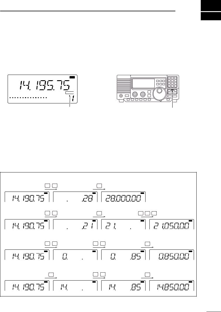
■ Using the keypad
qPush the numeral keys on the keypad to enter the MHz digits for the desired frequency.
•If a key is mistakenly pushed, push [CLR] and start again from the beginning.
•When entering the same MHz digits as the displayed frequency, this step can be skipped.
w Push [•] on the keypad.
ePush the numeral keys to enter the frequency digits below 1 MHz.
•If a key is mistakenly pushed, push [CLR] and start again from the beginning.
rPush [ENT] to set the input frequency.
•When pushing [ENT] after entering the MHz digits, zeros are automatically entered for the kHz digits.
[EXAMPLE]: Setting the frequency using the keypad.
•To set to 28.00 MHz
ABC2 TUV 8 |
ENT |
USB |
R X |
USB |
R X |
USB |
R X |
•To set to 21.050 MHz |
ABC2 |
1 |
|
. |
|
QZ 0 JKL 5 |
ENT |
|
USB |
R X |
|
USB |
R X |
USB |
R X |
USB |
R X |
•To set to 850 kHz (0.850 MHz)
|
QZ 0 |
. |
|
TUV 8 JKL 5 |
|
|
ENT |
|
USB |
R X |
|
USB |
R X |
USB |
R X |
USB |
R X |
•To change 14.19075 to 14.850 MHz
.
TUV 8 JKL 5 |
ENT |
USB |
R X |
USB |
R X |
USB |
R X |
USB |
R X |
11
4 FREQUENCY SETTING
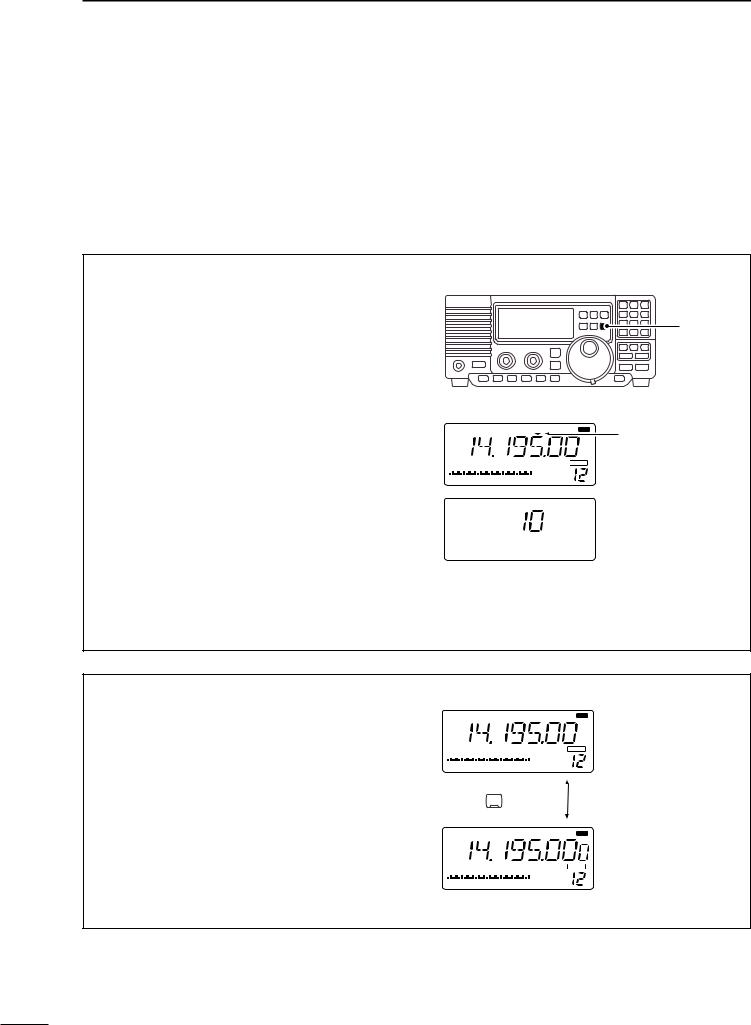
■ Frequency setting
Rotate the tuning dial to change the frequency.
•The frequency changes in increments determined by the selected tuning step (see below).
•When the lock function is activated (“LOCK” appears), the frequency cannot be changed via tuning dial.
Push [TS] one or more times to select a quick tuning step.
DProgrammable tuning steps
Programmable tuning steps are available to suit your operating requirements.
These tuning steps are:
•Independently selectable for each mode
•Selectable from 0.1, 1, 5, 6.25, 9, 10, 12.5, 20, 25, 100 kHz
qSelect the desired operating mode with [SSB], [CW/RTTY], [AM] or [FM]. (p. 14)
wPush [TS] one or more times until the programmable tuning step indicator, “",” appears above the 1 kHz.
•Rotating the tuning dial changes the frequency according to the set tuning step.
ePush [TS] for 2 sec. while the programmable tuning step indicator appears to enter the tuning step set mode.
rRotate the tuning dial to set the desired tuning step for the selected mode.
t Push [TS] to exit the tuning step set mode.
yRotate the tuning dial to change the frequency according to the set tuning step.
|
|
|
|
|
|
USB |
|
|
R X |
|
|
|
|
|
|
ANT 1 |
AGC |
BLANK |
|
S1 |
3 |
5 |
7 |
9 |
20 |
40 |
60dB |
|
VFO |
|
|
|
|
|
|
|
|
|
|
[TS]
Programmable tuning step indicator
10 kHz tuning step is selected.
D1 Hz and 10 Hz tuning steps
When both the 1 MHz tuning step and programmable tuning step, “",” disappear, rotating the tuning dial changes the frequency in increments of 1 or 10 Hz.
qPush [TS] one or more times until the programmable tuning step indicator or 1 MHz tuning step indicator, “",” disappears.
wPush [TS] for 2 sec. to toggle between the 1 and 10 Hz step settings.
•When the 1 Hz step is selected, the 1 Hz digit appears in the frequency indication; when the 10 Hz step is selected, the 1 Hz digit disappears from the frequency indication.
|
|
|
|
|
|
USB |
|
|
R X |
|
|
|
|
|
|
ANT 1 |
AGC |
BLANK |
|
S1 |
3 |
5 |
7 |
9 |
20 |
40 |
60dB |
VFO |
|
|
|
|
|
|
|
|
|
|
|
Push |
|
TS |
|
for 2 sec. |
|
||||
|
|
|
|
||||||
|
|
|
|
|
|
USB |
|
|
R X |
|
|
|
|
|
|
ANT 1 |
AGC |
BLANK |
|
S1 |
3 |
5 |
7 |
9 |
20 |
40 |
60dB |
VFO |
|
|
|
|
|
|
|
|
|
|
|
Rotating the tuning dial changes the frequency in 10 Hz steps.
Rotating the tuning dial changes the frequency in 1 Hz steps.
12
 Loading...