


INSTRUCTION MANUAL
VHF MARINE TRANSCEIVER
iM3A
This device complies with Part 15 of the FCC Rules. Operation is subject to the condition that this device does not cause harmful interference.

FOREWORD
Thank you for purchasing this Icom product. The IC-M3A VHF MARINE TRANSCEIVER is designed and built with Icom’s superior technology and craftsmanship. With proper care this product should provide you with years of trouble-free operation.
IMPORTANT
READ ALL INSTRUCTIONS carefully and com-
pletely before using the transceiver.
SAVE THIS INSTRUCTION MANUAL—This in-
struction manual contains important operating instructions for the IC-M3A.
EXPLICIT DEFINITIONS
WORD |
DEFINITION |
|
RWARNING |
Personal injury, fire hazard or electric shock |
|
may occur. |
||
|
|
|
CAUTION |
Equipment damage may occur. |
|
NOTE |
If disregarded, inconvenience only. No risk |
|
of personal injury, fire or electric shock. |
||
|
||
|
|
ii
FEATURES
Water-resistant construction
Built tough to withstand the punishing marine environment, the IC-M3A meets JIS water-resistant specification grade 4.
Dual watch and tri-watch functions
Convenient functions which allow you to monitor the distress channel (ch 16) while receiving a channel of your choice—dual watch; or monitor the distress channel and another channel while receiving a channel of your choice—tri-watch.
Large, easy-to-read LCD
With dimensions of 18(H) × 32(W) mm, the IC-M3A’s function display is easy to read and shows operating conditions at a glance. Backlighting and contrast can be adjusted to suit your preferences.
Simple operation
Ergonomic design with a minimum number of switches and controls provides simple intuitive operation.

CAUTIONS
RWARNING! NEVER connect the transceiver to an AC outlet. This may pose a fire hazard or result in an electric shock.
RWARNING! NEVER hold the transceiver so that the antenna is very close to, or touching exposed parts of the body, especially the face or eyes, while transmitting. The transceiver will perform best if the microphone is 5 to 10 cm away from the lips and the transceiver is vertical.
NEVER connect the transceiver to a power source other than the BP-204. Such a connection will ruin the transceiver.
AVOID using or placing the transceiver in direct sunlight or in areas with temperatures below –20°C (–4°F) or above +60°C (+140°F).
KEEP the transceiver out of the reach of children.
KEEP the transceiver at least 1 meter away from your vessel’s magnetic navigation compass.
IN CASE OF EMERGENCY
If your vessel requires assistance, contact other vessels and the Coast Guard by sending a distress call on channel 16.
USING CHANNEL 16
DISTRESS CALL PROCEDURE
1. |
“MAYDAY MAYDAY MAYDAY.” |
|
2. |
“THIS IS |
...........................” (name of vessel) |
3.Your call sign or other indication of the vessel.
4. “LOCATED AT |
.....................” (your position) |
5.The nature of the distress and assistance required.
6.Any other information which might facilitate the rescue.
iii

TABLE OF CONTENTS
FOREWORD ....................................................................... |
ii |
IMPORTANT ........................................................................ |
ii |
EXPLICIT DEFINITIONS ..................................................... |
ii |
FEATURES .......................................................................... |
ii |
CAUTIONS ......................................................................... |
iii |
IN CASE OF EMERGENCY ............................................... |
iii |
TABLE OF CONTENTS ...................................................... |
iv |
1 OPERATING RULES ...................................................... |
1 |
2 PANEL DESCRIPTION ............................................... |
2–4 |
■ Front panel .................................................................. |
2 |
■ Top and side panels .................................................... |
3 |
■ Function display .......................................................... |
4 |
3 BASIC OPERATION ................................................. |
5–10 |
■ Channel selection ........................................................ |
5 |
■ Lock function ............................................................... |
6 |
■ Adjusting the squelch level .......................................... |
6 |
■ Receiving and transmitting .......................................... |
7 |
■ Call channel programming .......................................... |
8 |
■ Automatic backlighting ................................................ |
8 |
4 DUALWATCH/TRI-WATCH ............................................ |
9 |
■ Description .................................................................. |
9 |
iv
|
■ Operation ..................................................................... |
9 |
5 |
SCAN OPERATION ................................................. |
10-11 |
|
■ Scan types ................................................................. |
10 |
|
■ Setting tag channels .................................................. |
11 |
|
■ Starting a scan ........................................................... |
11 |
6 |
SET MODE .............................................................. |
12-13 |
|
■ SET mode programming ........................................... |
12 |
|
■ SET mode items ........................................................ |
12 |
7 |
BATTERY CHARGING ............................................ |
14-15 |
|
■ Installing batteries in the battery case ....................... |
14 |
|
■ Battery charging ........................................................ |
14 |
|
■ Battery cautions ......................................................... |
15 |
8 |
SUPPLIED ACCESSORIES ......................................... |
16 |
9 |
TROUBLESHOOTING .................................................. |
17 |
10 CHANNEL LIST ........................................................... |
18 |
|
11 SPECIFICATIONS AND OPTIONS ............................. |
19 |
|
|
■ Specifications ............................................................ |
19 |
|
■ Options ...................................................................... |
19 |

D Priorities
•Read all rules and regulations pertaining to priorities and keep an up-to-date copy handy. Safety and distress calls take priority over all others.
•You must monitor channel 16 when you are not operating on another channel.
•False or fraudulent distress calls are prohibited under law.
D Privacy
•Information overheard but not intended for you cannot lawfully be used in any way.
•Indecent or profane language is prohibited.
D Radio licenses
SHIP STATION LICENSE
When your craft is equipped with a VHF FM transceiver, you must have a current radio station license before using the transceiver. It is unlawful to operate a ship station which is not licensed.
Inquire through your dealer or the appropriate government agency for a Ship-Radiotelephone license. This license includes the call sign which is your craft’s identification for radio purposes.
OPERATING RULES 1
OPERATOR’S LICENSE
A restricted Radiotelephone Operator Permit is the license most often held by small vessel radio operators when a radio is not required for safety purposes.
The Restricted Radiotelephone Operator Permit must be posted near the transceiver or be kept with the operator. Only a licensed radio operator may operate a transceiver.
However, non-licensed individuals may talk over a transceiver if a licensed operator starts, supervises, ends the call and makes the necessary log entries.
A current copy of the applicable government rules and regulations is only required to be on hand for vessels in which a radio telephone is compulsory. However, even if you are not required to have these on hand it is your responsibility to be thoroughly acquainted with all pertinent rules and regulations.
NOTE: Even though the IC-M3A is capable of operation on VHF marine channels 3, 21, 23, 61, 64, 81, 82 and 83, according to FCC regulations these simplex channels cannot be lawfully used by the general public in USA waters.
1
 2 PANEL DESCRIPTION
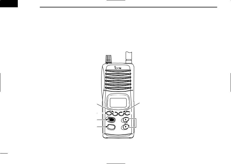
■ Front panel
q DUALWATCH /TRI-WATCH SWITCH [DW•TRI]
•Starts dualwatch when pushed momentarily.
•Starts tri-watch when pushed for 1 sec.
•Stops dualwatch/tri-watch when either is activated.
w SQUELCH SWITCH [SQL]
•Push this switch, then set the squelch level with the UP/DOWN [  ]/[
]/[  ] switches. (p. 6)
e CHANNEL 16 SWITCH [16 • 9]
•Selects channel 16 when pushed.
•Selects the call channel when pushed for 1 sec.
•Enters call channel write mode when the call channel is selected and this switch is pushed for 3 sec.
r CHANNEL/WEATHER CHANNEL SWITCH [CH/WX•U/I/C]
•Selects and toggles the regular channels and weather channel when pushed momentarily.
•Selects one of 3 regular channels in sequence when pushed for 1 sec.
q
w e r
VHF MARINE
H
9 |
|
/ |
/C |
U I |
|
/ |
|
WX |
|
iM3A
-International, U.S.A. and Canadian channels are available.
t SCAN/TAG SWITCH [SCAN • TAG]
•Starts and stops normal or priority scan when tag channels are programmed.
•Sets and clears the displayed channel as a tag (scanned) channel when pushed for 1 sec.
•While pushing this switch, turn the power ON to clears all tag channels in the selected regular channel group.
y TRANSMIT POWER/LOCK SWITCH [H/L • LOCK]
•Toggles high and low power when pushed.
•Toggles the lock function ON/OFF when
t pushed for 1 sec.
u CHANNEL UP/DOWN SWITCHES
 y [
y [  ]/[
]/[  ]
]
• Select an operating channel in the selected  u channel group.
• Selects the set mode condition of the item.
2

|
|
PANEL DESCRIPTION 2 |
■ Top and side panels |
|
|
q PTT SWITCH [PTT] |
|
ï BATTERY CASE RELEASE BUTTON |
Push and hold to transmit; |
|
To remove the battery case: |
release to receive. |
w |
Push and hold the battery release button downwards, then |
|
e |
open the battery case as shown below. |
w VOLUME CONTROL |
|
To attach the battery case: |
[OFF/VOL] |
|
Mate the notched ends of the transceiver and battery |
Turns power ON and ad- |
|
case,and click the battery case into place. |
justs the audio level. |
|
|
q
e ANTENNA CONNEC-
TOR
Connects the supplied antenna.
3
2 PANEL DESCRIPTION
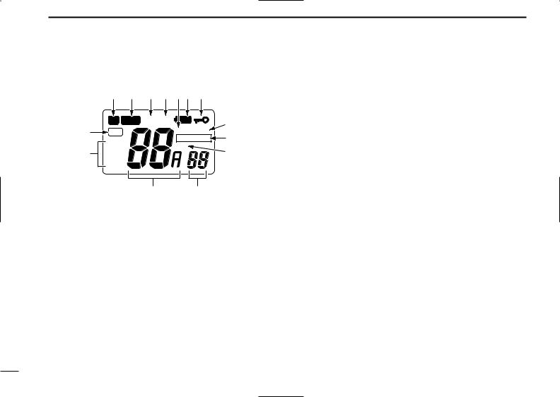
■ Function display
q w e r ty u
|
TX |
BUSY CALL LOW BATT |
i |
|
|
|
|
ALT SCAN |
|
!4 TAG |
|
|
||
|
WX |
|
DUAL TRI o |
|
|
|
DUP |
|
|
!3 |
USA |
|
!0 |
|
|
|
|||
INT |
|
|
||
|
|
|
|
|
|
CAN |
|
|
|
|
|
!2 |
!1 |
|
q TRANSMIT INDICATOR
Appears while transmitting. (p. 8) w BUSY INDICATOR
Appears when receiving a signal or when the squelch level is set to the “OFF” position. (p. 8)
e CALL CHANNEL INDICATOR
Appears when the call channel is selected. (p. 9) r LOW POWER INDICATOR
Shows that low output power is selected. t WEATHER ALERT INDICATOR
Appears while the weather alert function is activated; blinks when an alert tone is received.
y LOW BATTERY INDICATOR
Blinks when the battery voltage drops to approx. 6 V or below. The attached Ni-Cd batteries require charging in this
case.
u LOCK INDICATOR
Appears while the lock function activated. i SCAN INDICATOR
Blinks while scanning.
o DUALWATCH/TRI-WATCH INDICATORS
“DUAL” appears during dualwatch; “TRI” appears during tri-watch. (p. 10)
!0DUPLEX INDICATOR
Appears when a duplex channel is selected.
!1SET MODE INDICATOR
Shows the set mode items. (pgs. 13)
!2CHANNEL INDICATOR
•Indicates the selected operating channel number. (p. 6)
•In set mode, indicates the selected condition. (p. 13)
!3MODE INDICATORS (p. 6)
•“USA” shows that USA channels are selected.
•“CAN” shows that Canadian channels are selected.
•“INT” shows that international channels are selected.
•“WX” shows that weather channels are selected.
!4TAG CHANNEL INDICATOR
Appears when a tag channel is selected.
4
 Loading...