


INSTRUCTION MANUAL
VHF MARINE TRANSCEIVER
iCm1
This device complies with Part 15 of the FCC Rules. Operation is subject to the condition that this device does not cause harmful interference.

IMPORTANT
READ ALL INSTRUCTIONS carefully and completely |
SAVE THIS INSTRUCTION MANUAL — This in- |
before using the transceiver. |
struction manual contains important operating instructions for |
|
the IC-M1. |
|
|
CAUTIONS |
|
RWARNING! NEVER hold the transceiver so that the antenna is very close to, or touching exposed parts of the body, especially the face or eyes, while transmitting. The transceiver will perform best if the microphone is 2 to 4 in (5 to 10 cm) away from the lips and the transceiver is vertical.
MAKE SURE the flexible antenna and battery pack are securely attached to the transceiver and that the antenna and battery pack are dry before attachment. Exposing the inside of the transceiver to water will result in serious damage to the transceiver.
NEVER allow children to touch the transceiver.
NEVER charge battery packs except in the methods de-
scribed in this manual.
i
KEEP the transceiver at least 3.3 ft (1 m) away from the ship’s navigation compass.
DO NOT use or place the transceiver in areas with temperatures below –4°F (–20°C) or above +140°F (+60°C) or, in areas subject to direct sunlight, such as the dashboard.
AVOID the use of chemical agents such as benzine or alcohol when cleaning, as they may damage the transceiver surfaces.
BE CAREFUL! The transceiver rear panel will become hot when operating continuously for long periods.
After exposure to saltwater, clean the transceiver thoroughly with fresh water to avoid corrosion.

TABLE OF CONTENTS
IMPORTANT ........................................................................ |
i |
|
CAUTIONS .......................................................................... |
i |
|
TABLE OF CONTENTS ..................................................... |
ii |
|
1 |
PANEL DESCRIPTION ............................................. |
1–3 |
|
■ Front panel ................................................................. |
1 |
|
■ Top and side panels ................................................... |
2 |
|
■ Function display ......................................................... |
3 |
2 |
BASIC OPERATION ................................................. |
4–9 |
|
■ Operating rules .......................................................... |
4 |
|
■ Channel selection ...................................................... |
5 |
|
■ Lock function .............................................................. |
6 |
|
■ Adjusting the squelch level ........................................ |
6 |
|
■ Receiving and transmitting ........................................ |
7 |
|
■ Optional voice scrambler operation ........................... |
8 |
|
■ Call channel programming ......................................... |
9 |
|
■ Automatic backlighting ............................................... |
9 |
3 |
DUALWATCH/TRI-WATCH ......................................... |
10 |
|
■ Description ............................................................... |
10 |
|
■ Operation ................................................................. |
10 |
4 |
SCAN OPERATION .............................................. |
11–12 |
|
■ Scan types ............................................................... |
11 |
|
■ Setting tag channels ................................................ |
12 |
|
■ Starting a scan ......................................................... |
12 |
5 |
SET MODE ........................................................... |
13–14 |
|
■ SET mode programming .......................................... |
13 |
|
■ SET mode items ...................................................... |
13 |
6 |
BATTERY CHARGING ......................................... |
15–16 |
|
■ Battery cautions ....................................................... |
15 |
|
■ Battery charging ...................................................... |
15 |
7 |
UNPACKING AND ACCESSORY ATTACHMENT |
..... 17 |
8 |
TROUBLESHOOTING ................................................ |
18 |
9 |
CHANNEL LIST .......................................................... |
19 |
10 |
SPECIFICATIONS AND OPTIONS ............................ |
20 |
|
■ Specifications ........................................................... |
20 |
|
■ Options .................................................................... |
20 |
ii
 1 PANEL DESCRIPTION
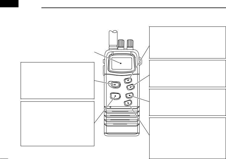
■Front panel
FUNCTION DISPLAY (p. 3)
CHANNEL 16 SWITCH [16•9]
• Selects channel 16 when pushed. (p. 5)
• Selects the call channel when pushed for 1 sec. (p. 5)
• Enters call channel write mode when the call channel is selected and this switch is pushed for 3 sec. (p. 9)
CHANNEL/WEATHER CHANNEL SWITCH [CH/WX•U/I/C]
• Selects and toggles the regular channels and weather channel when pushed momentarily. (pgs. 5, 6)
•Selects one of 3 regular channels in sequence when pushed for 1 sec. (p. 5)
-International, U.S.A. and Canadian channels are available for regular channels.
DUALWATCH/TRI-WATCH SWITCH [DW•TRI] (p. 10)
•Starts dualwatch when pushed momentarily.
•Starts tri-watch when pushed for 1 sec.
•Stops dualwatch/tri-watch when either is activated.
SCAN SWITCH [SCN•SCRM]
•Starts and stops normal or priority scan when tag channels are programmed. (p. 12)
•Activates an optional voice scrambler function when pushed for 1 sec. (p. 8)
TAG SWITCH [TAG•ALL CLR]
•Sets the displayed channel as a tag (scanned) channel when pushed. (p. 12)
•Clears all tag channels in the selected regular channel when pushed for 3 sec. (p. 12)
TRANSMIT POWER/LOCK SWITCH [H/L•LOCK]
•Toggles high power and low power (1 W) when pushed. (p. 7)
•While pushing [SQL], push this key to select extra low power (150 mW). (p. 7)
•Toggles the lock function ON and OFF when pushed for 1 sec. (p. 6)
1

■Top and side panels
SQUELCH/MONITOR SWITCH [SQL]
•Opens the squelch and monitors the operating channel while being pushed.
•Sets the squelch level with the channel selector. (p. 6)
PTT SWITCH [PTT]
Push and hold to transmit; release to receive. (p. 7)
BATTERY PACK RELEASE BUTTON
To remove the battery pack:
Push and hold the battery release button downwards, then open the battery pack as shown below.
To attach the battery pack:
Mate the notched ends of the transceiver and the battery pack, and click the battery pack into place.
PANEL DESCRIPTION 1
ANTENNA CONNECTOR (p. 17) Connects the supplied antenna.
VOLUME CONTROL [OFF/VOL]
Turns power ON and adjusts the audio level. (p. 7)
CHANNEL SELECTOR [CH]
•Sets an operating channel during normal operation. (pgs. 5, 6)
•Sets a squelch threshold level while pushing [SQL]. (p. 6)
•Checks tag channels or changes scanning direction during scan. (p. 12)
•Selects the set mode contents in SET mode. (pgs. 13, 14)
•Selects the optional scrambler code when [SCN•SCRM] is pushed and held. (p. 8)
2
1 PANEL DESCRIPTION
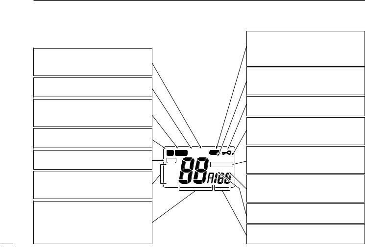
■Function display
LOW POWER INDICATOR (p. 7)
•Appears when low power is selected.
•Blinks when extra low power is selected.
CALL CHANNEL INDICATOR (p. 5) Appears when a call channel is selected.
BUSY INDICATOR (p. 7)
Appears when receiving a signal or when the squelch opens.
TRANSMIT INDICATOR (p. 7)
Appears while transmitting.
TAG CHANNEL INDICATOR (p. 12) Appears when a tag channel is selected.
CHANNEL INDICATORS (pgs. 5, 6) Indicate whether a U.S.A., international, Canadian or weather channel is selected.
CHANNEL NUMBER READOUT
•Indicates the selected operating channel number. (pgs. 5, 6)
•In SET mode, indicates the selected condition. (pgs. 13, 14)
TX |
CALL |
TAG |
SCAN |
WX |
DUAL TRI |
|
|
USA |
|
INT |
|
CAN |
|
LOW BATTERY INDICATOR (p. 15) Blinks when the battery voltage drops to approx. 6 V or below. The attached battery pack requires charging in this case.
WEATHER ALERT INDICATOR (p. 14) Appears while the weather alert function is activated; blinks when alert tone is received.
LOCK INDICATOR (p. 6)
Appears while the lock function is activated.
SCAN INDICATOR (pgs. 12, 14)
Blinks while scanning; appears when the auto scan function is in standby.
DUALWATCH/TRI-WATCH INDICATORS
“DUAL” appears during dualwatch; “TRI” appears during tri-watch. (p. 10)
SCRAMBLER INDICATOR (p. 8)
Appears when the optional voice scrambler is activated.
DUPLEX INDICATOR
Appears when a duplex channel is selected.
SCRAMBLE CODE READOUT (p. 8) Shows the scrambler code while setting.
3

■Operating rules
• PRIORITIES
1Read all rules and regulations pertaining to priorities and keep an up-to-date copy handy. Safety and distress calls take priority over all others.
2You must monitor channel 16 when you are not operating on another channel.
3False or fraudulent distress signals are prohibited and punishable by law.
• PRIVACY
1Information overheard but not intended for you cannot lawfully be used in any way.
2 Indecent or profane language is prohibited.
• RADIO LICENSES
(1) SHIP STATION LICENSE
You must have a current radio station license before using the transceiver. It is unlawful to operate a ship station which is not licensed.
BASIC OPERATION 2 
Inquire through your dealer or the appropriate government agency for a Ship-Radiotelephone license application. This government-issued license states the call sign which is your craft’s identification for radio purposes.
(2) OPERATOR’S LICENSE
A Restricted Radiotelephone Operator Permit is the license most often held by small vessel radio operators when a radio is not required for safety purposes.
The Restricted Radiotelephone Operator Permit must be posted or kept with the operator. Only a licensed radio operator may operate a transceiver.
However, non-licensed individuals may talk over a transceiver if a licensed operator starts, supervises, ends the call and makes the necessary log entries.
Keep a copy of the current government rules and regulations handy.
4
2 BASIC OPERATION
■Channel selection
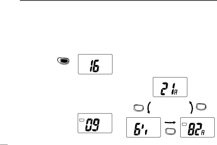
DChannel 16
Channel 16 is the distress channel. It is used for establishing initial contact with another station and for emergency communications. Channel 16 is monitored during dualwatch/ tri-watch. While standing by you are required to monitor channel 16.
|
9 |
Push |
16 |
USA
DChannel 9 (Call channels)
Channel 9 is the pleasure call channel. Each regular channel group has separate call channels. In addition, each call channel is monitored during tri-watch. The call channels can be programmed (p. 9) and are used to store your most oftenused channels in each channel group for quick recall.
• Push [16•9] for 1 sec. to select
the call channel of the selected |
CALL |
TAG |
|
channel group. |
USA |
|
-“CALL” and call channel number appear.
-Each channel group may have an independent call channel after changing a call channel.
DU.S.A., Canadian and international channels
There are 61 U.S.A., 57 Canadian and 57 international channels. These channel groups may be specified for the operating area.
1Push [CH/WX] to select a regular channel.
- If a weather channel appears, push [CH/WX] again.
2Rotate the channel selector to select a channel.
- “DUP” appears for duplex channels.
3To change the channel group, push [CH/WX•U/I/C] for 1 sec.
-U.S.A., Canadian and international channels can be selected in sequence.
USA
Push for 1 sec. |
U.S.A. channels |
|
|
U/I/C |
U/I/C |
|
|
CH/WX |
CH/WX |
|
 DUP
DUP
INT
International channels
TAG
U/I/C
CH/WX
CAN
Canadian channels
5
 Loading...