


INSTRUCTION MANUAL
VHF TRANSCEIVER
iF111
iF121
UHF TRANSCEIVER
iF211
iF221

IMPORTANT
READ ALL INSTRUCTIONS carefully and com-
pletely before using the transceiver.
SAVE THIS INSTRUCTION MANUAL — This
instruction manual contains important operating instructions for the IC-F111/F121 VHF TRANSCEIVER and IC-F211/F221 UHF TRANSCEIVER.
EXPLICIT DEFINITIONS
WORD |
DEFINITION |
|
RWARNING |
Personal injury, fire hazard or electric shock |
|
may occur. |
||
|
|
|
CAUTION |
Equipment damage may occur. |
|
NOTE |
If disregarded, inconvenience only. No risk |
|
of personal injury, fire or electric shock. |
||
|
||
|
|
Icom, Icom Inc. and the 
 logo are registered trademarks of Icom Incorporated (Japan) in the United states, the United Kingdom, Germany, France, Spain, Russia and/or other countries. SmarTrunk II™ is a trademark of the SmarTrunk Systems, Inc.
PRECAUTION
RWARNING! NEVER connect the transceiver to an AC outlet. This may pose a fire hazard or result in an electric shock.
CAUTION! NEVER touch the transceiver (especially the heat sink) when transmitting continuously for long periods. It will become hot.
NEVER connect the transceiver to a power source of more than 16 V DC such as a 24 V battery. This connection will ruin the transceiver.
NEVER cut the DC power cable between the DC plug and fuse holder. If an incorrect connection is made after cutting, the transceiver might be damaged.
NEVER place the transceiver where normal operation of the vehicle may be hindered or where it could cause bodily injury.
NEVER allow children to touch the transceiver.
NEVER expose the transceiver to rain, snow or any liquids.
i

USE the supplied microphone only. Other microphones have different pin assignments and may damage the transceiver.
DO NOT use or place the transceiver in areas with temperatures below –22°F (–30°C) or above +140°F (+60°C), or in areas subject to direct sunlight, such as the dashboard.
AVOID operating the transceiver without running the vehicle’s engine. The vehicle’s battery will quickly run out if the transceiver transmits while the vehicle’s engine OFF.
AVOID placing the transceiver in excessively dusty environments.
AVOID placing the transceiver against walls. This will obstruct heat dissipation.
AVOID the use of chemical agents such as benzine or alcohol when cleaning, as they damage the transceiver surfaces.
For U.S.A. only
CAUTION: Changes or modifications to this transceiver, not expressly approved by Icom Inc., could void your authority to operate this transceiver under FCC regulations.
TABLE OF CONTENTS |
|
IMPORTANT .................................................................................... |
i |
EXPLICIT DEFINITIONS ................................................................. |
i |
PRECAUTION .................................................................................. |
i |
TABLE OF CONTENTS .................................................................. |
ii |
1 PANEL DESCRIPTION ........................................................... |
1–6 |
■ Front panel ............................................................................... |
1 |
■ Function display ....................................................................... |
2 |
■ Programmable function keys .................................................... |
3 |
2 OPERATION .......................................................................... |
7–10 |
■ Turning power ON .................................................................... |
7 |
■ Channel selection ..................................................................... |
7 |
■ Receiving and transmitting ....................................................... |
8 |
DTransmitting notes ................................................................. |
8 |
DTX code channel selection .................................................... |
9 |
DTX code number selection .................................................... |
9 |
DDTMF transmission ............................................................... |
9 |
DScrambler function ................................................................ |
9 |
DUser set mode ..................................................................... |
10 |
3 OPTIONAL SmarTrunk IITM OPERATION .......................... |
11–12 |
■ SmarTrunk IITM and conventional modes ............................... |
11 |
■ SmarTrunk IITM operation ....................................................... |
11 |
4 CONNECTION AND MAINTENANCE ................................ |
13–17 |
■ Rear panel and connection .................................................... |
13 |
■ Supplied Accessories ............................................................. |
14 |
■ Mounting the transceiver......................................................... |
15 |
■ Optional UT-105, UT-108 or UT-111 installation ..................... |
15 |
■ Optional UT-109 or UT-110 installation .................................. |
16 |
■ Optional OPC-617 installation................................................. |
16 |
■ Antenna ................................................................................... |
17 |
■ Fuse replacement .................................................................. |
17 |
■ Cleaning ................................................................................. |
17 |
5 OPTIONS ................................................................................... |
18 |
6 SAFETY TRAINING INFORMATION ........................................ |
19 |
ii

 1 PANEL DESCRIPTION
■Front panel
q |
w |
e |
y |
t |
qAF VOLUME CONTROL KNOB
Rotate the knob to adjust the audio output level.
• Minimum audio level is pre-programmed.
wFUNCTION DISPLAY
Displays a variety of information, such as an operating channel number/name, 5-tone code, DTMF numbers and audible condition, etc.
NOTE: The above functions depend on pre-programming.
r
eUP/DOWN [ ]/[
]/[ ] KEYS
Push to select the operating channel.
Can be programmed for one of several functions by your dealer. (Same as [P0] to [P3] keys)
rPOWER SWITCH [POWER]
Push to turn the power ON and OFF.
•The following functions are available at power ON as options:
-Automatic scan start
-Password prompt
-Set mode
1
tDEALER-PROGRAMMABLE KEYS [P0] to [P3]
Desired functions can be programmed independently by your dealer.
yMICROPHONE CONNECTOR
Connect the supplied microphone or optional DTMF microphone for SmarTrunk IITM operation here.
NEVER connect non-specified microphones. The pin assignments may be different and the transceiver may be damaged.
D MICROPHONE
The supplied microphone has a PTT switch and a hanger hook.
•The following functions are available when the microphone is on or off hook:
-Automatic scan start when on hook.
-Automatic priority channel selection when off hook.
-Sets to ‘Inaudible’ condition (mute condition) when on hook.
-Sets to ‘Audible’ condition (unmute condition) when off hook.
PANEL DESCRIPTION 1
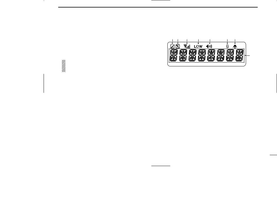
■Function display
q w |
e |
r |
t |
y |
u |
|
|
|
|
|
i |
qTRANSMIT INDICATOR
Appears while transmitting.
wBUSY INDICATOR
Appears while the channel is busy.
eSIGNAL STRENGTH METER
Indicates relative receive signal strength level.
rLOW POWER INDICATOR
Appears when low output power is selected.
tAUDIBLE INDICATOR
Appears when the channel is in the ‘Audible’ condition (unmute condition).
ySCRAMBLER INDICATOR
Appears when the scrambler function is activated. (Optional UT-109 (#02)/UT-110 (#02) SCRAMBLER UNIT is required.)
2

1 PANEL DESCRIPTION
u2/5TONE INDICATOR
Appears when the specified 2/5-tone call is received.
i ALPHANUMERIC DISPLAY
Displays the CH number, 5-tone indication, DTMF numbers, Audible indication, etc.
■Programmable function keys
The following functions can be assigned to [P0], [P1], [P2], [P3], [ ] and [
 ] programmable function keys.
Consult your Icom dealer for details concerning your transceiver’s programming.
In the following explanations, programmable function names are bracketed. The specific switch used to activate the function depends on programming.
¡ CH UP AND DOWN KEYS
CH UP |
Select an operating channel. |
|
CH DN |
Select a transmit code channel after pushing |
|
the [TX CH] key. |
||
|
Select a DTMF channel after pushing the
[DTMF] key.
Select a scan group after pushing and holding the [SCAN] key.
¡BANK KEY
BANK Select and determine a bank number.
•When the optional UT-105 is installed, push one or more times to select a channel bank for conventional channels or SmarTrunk II TM channels.
3

¡ SCAN START/STOP KEY
SCAN A Push this key to start scanning; and push again
to stop.
SCAN B
NOTE: Place the microphone on hook to start scanning.
Take the microphone off hook to stop scanning.
¡ SCAN TAG KEY
TAG |
Adds or deletes the selected channel to the scan |
|
|
group. |
|
¡ PRIORITY CHANNEL KEYS |
||
PRI A |
Push these keys to select priority A or priority B |
|
channel, respectively. |
||
PRI B |
||
|
||
¡ OPERATING CHANNEL KEYS |
||
CH1 |
Select an operating channel directly. |
|
CH2
CH3
CH4
PANEL DESCRIPTION 1
¡ MONITOR KEY
MONI |
Activates one of (or two of) the following functions |
on each channel independently:
•Push and hold the key to unmute the channel (audio is emitted; ‘Audible’ condition).
•Push the key to toggle between the mute and unmute conditions (toggles between ‘Audible’ and ‘Inaudible’).
•Push the key to mute the channel (sets to ‘Inaudible’ only).
•Push the key to unmute the channel (sets to ‘Audible’ only).
•Push the key after communication is finished to send a ‘reset code’.
NOTE: The unmute condition (‘Audible’ condition) may automatically return to the mute condition (‘Inaudible’ condition) after a specified period depending on the pre-setting.
¡ LOCK KEY
LOCK |
Push this key for 1 sec. to lock all programmable |
|
keys except the following: |
||
|
•[CALL] (incl. [CAL A] and [CAL B]), [MONI] and
[EMER] keys.
4

1 PANEL DESCRIPTION
¡ OUTPUT POWER SELECTION KEYS
H/L |
Select the transmit output power temporarily, or |
|
permanently, depending on the pre-setting. |
•Contact your dealer for the output power level for each selection.
¡TALK AROUND KEY
TA |
Turns the talk around function ON and OFF. |
•The talk around function equalizes the transmit frequency to the receive frequency for mobile-to-mobile communication.
¡WIDE/NARROW KEY
W/N |
Push this key to toggle the bandwidth between |
|
wide or narrow. |
¡ DTMF AUTODIAL KEY |
|
DTMF |
Push this key to display the text of the DTMF |
|
channel number and set the desired channel |
number via the [ ]/[
]/[ ] key. Then, push this key again to transmit a specified DTMF code.
¡ CALL KEY
CALL Transmit a 2-tone, 5-tone code.
•Call transmission is necessary before you call another station depending on your signaling system.
CAL A • The [CAL A] and/or [CAL B] keys may be available when your system employs selective ‘Individual/Group’
CAL B
calls. Contact your dealer about which call is assigned to each key.
¡ EMERGENCY KEY
EMER Push and hold the key to transmit an emergency call.
•If you want to cancel the emergency call, push and hold (or push) the key again before transmitting the call.
•Depending on the pre-setting, the emergency call is transmitted one time only, or repeatedly, until receiving a control code.
¡HOOK SCAN
HOOK |
When the Hook Scan function is turned ON, push |
|
this key to stop scanning temporarily. Push this |
|
key again to re-start scanning. |
¡ TX CODE KEY |
|
TX CH |
Select a transmit 5-tone code (station code) chan- |
|
nel. |
5
 Loading...