


INSTRUCTION MANUAL
VHF TRANSCEIVER
iF111S
iF121S
UHF TRANSCEIVER
iF211S
iF221S

IMPORTANT
READ ALL INSTRUCTIONS carefully and com-
pletely before using the transceiver.
SAVE THIS INSTRUCTION MANUAL — This
instruction manual contains important operating instructions for the IC-F111S/F121S VHF TRANSCEIVER and ICF211S/F221S UHF TRANSCEIVER.
EXPLICIT DEFINITIONS
WORD |
DEFINITION |
|
RWARNING |
Personal injury, fire hazard or electric shock |
|
may occur. |
||
|
|
|
CAUTION |
Equipment damage may occur. |
|
NOTE |
If disregarded, inconvenience only. No risk |
|
of personal injury, fire or electric shock. |
||
|
||
|
|
Icom, Icom Inc. and the 
 logo are registered trademarks of Icom Incorporated (Japan) in the United states, the United Kingdom, Germany, France, Spain, Russia and/or other countries.
SmarTrunk II™ is a Trademark of SmarTrunk Systems, Inc.
PRECAUTION
RWARNING! NEVER connect the transceiver to an AC outlet. This may pose a fire hazard or result in an electric shock.
CAUTION! NEVER touch the transceiver (especially the heat sink) when transmitting continuously for long periods. It will become hot.
NEVER connect the transceiver to a power source of more than 16 V DC such as a 24 V battery. This connection will ruin the transceiver.
NEVER cut the DC power cable between the DC plug and fuse holder. If an incorrect connection is made after cutting, the transceiver might be damaged.
NEVER place the transceiver where normal operation of the vehicle may be hindered or where it could cause bodily injury.
NEVER allow children to touch the transceiver.
NEVER expose the transceiver to rain, snow or any liquids.
i

USE the supplied microphone only. Other microphones have different pin assignments and may damage the transceiver.
DO NOT use or place the transceiver in areas with temperatures below –22°F (–30°C) or above +140°F (+60°C), or in areas subject to direct sunlight, such as the dashboard of a vehicle.
AVOID operating the transceiver without running the vehicle’s engine. The vehicle’s battery will quickly run out if the transceiver is in transmission while the vehicle’s engine OFF.
AVOID placing the transceiver in excessively dusty environments.
AVOID placing the transceiver against walls. This will obstruct heat dissipation.
AVOID the use of chemical agents such as benzine or alcohol when cleaning, as they damage the transceiver surfaces.
For U.S.A. only
CAUTION: Changes or modifications to this transceiver, not expressly approved by Icom Inc., could void your authority to operate this transceiver under FCC regulations.
TABLE OF CONTENTS |
|
IMPORTANT .................................................................................... |
i |
EXPLICIT DEFINITIONS ................................................................. |
i |
PRECAUTION .................................................................................. |
i |
TABLE OF CONTENTS .................................................................. |
ii |
1 PANEL DESCRIPTION ........................................................... |
1–5 |
■ Front panel ............................................................................... |
1 |
■ Function LED ........................................................................... |
2 |
■ Programmable function keys .................................................... |
3 |
2 OPERATION ............................................................................ |
6–8 |
■ Turning power ON .................................................................... |
6 |
■ Channel selection ..................................................................... |
6 |
■ Receiving and transmitting ....................................................... |
7 |
DTransmitting notes ................................................................. |
7 |
DScrambler function ................................................................ |
8 |
DUser set mode ....................................................................... |
8 |
3 CONNECTION AND MAINTENANCE .................................. |
9–13 |
■ Rear panel and connection ...................................................... |
9 |
■ Supplied Accessories ............................................................. |
10 |
■ Mounting the transceiver ......................................................... |
11 |
■ Optional UT-108 installation ................................................... |
11 |
■ Optional UT-109/UT-110 installation ...................................... |
12 |
■ Optional OPC-617 installation................................................. |
12 |
■ Antenna ................................................................................... |
13 |
■ Fuse replacement .................................................................. |
13 |
■ Cleaning ................................................................................. |
13 |
4 OPTIONS ................................................................................... |
14 |
5 SAFETY TRAINING INFORMATION ........................................ |
15 |
ii

 1 PANEL DESCRIPTION
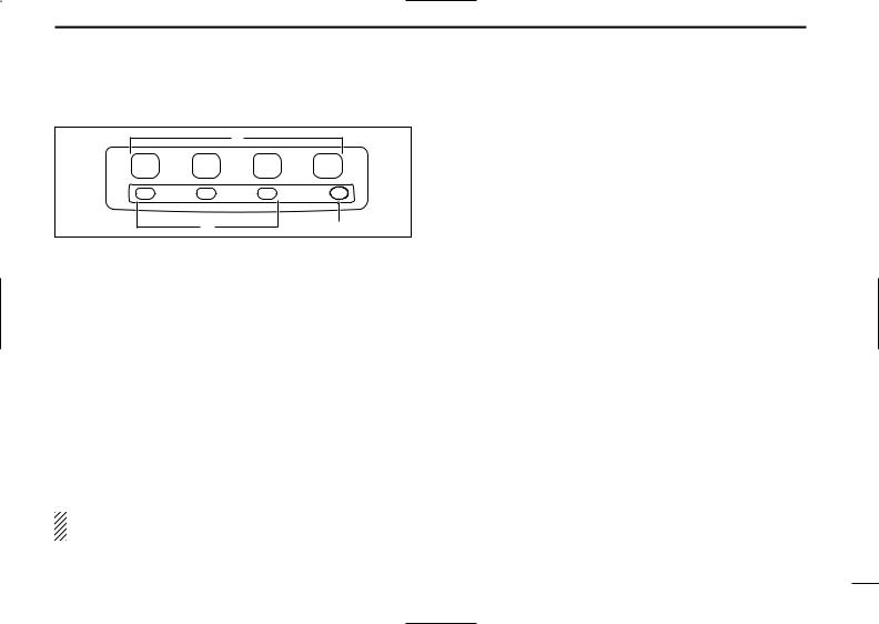
■Front panel
q Function LED (p. 2)
1 |
2 |
3 |
4 |
|
|
|
TX/RX |
w |
|
e |
r |
q |
AF |
VOLUME |
be damaged. |
CONTROL KNOB |
|
|
|
Rotate the knob to adjust the audio output level.
• Minimum audio level is pre-programmed.
wMICROPHONE CONNECTOR
Connect the supplied microphone or optional DTMF microphone.
NEVER connect non-specified microphones. The pin assignments may be different and the transceiver may
1
■Function LED
q
1 |
2 |
3 |
4 |
|
|
|
TX/RX |
|
e |
|
w |
q |
|
CHANNEL INDICA- |
|
TORS
Indicates the operating channel.
Blinks when receiving a signal during scanning operation.
All LEDs blink while entering the power ON password.
wTX/RX INDICATOR
Lights red: while transmitting
Lights green: while the channel is busy
Blinks orange (green and red blink simultaneously): when the specified 2-tone, 5-tone call is received.
Green and red blink alternately: cloning error
eACTIVATED KEY INDICATOR (LP 0/1/2)
Appears when a pre-programmed key function is activated.
NOTE: When all function LEDs blink, check the DC battery voltage is not too high.
PANEL DESCRIPTION 1
D MICROPHONE
The supplied microphone has a PTT switch and a hanger hook.
•The following functions are available when the microphone is on or off hook:
-Automatic scan start when hook on.
-Automatic priority channel selection when hook off.
-Sets to ‘Inaudible’ condition (mute condition) when hook on.
-Sets to ‘Audible’ condition (unmute condition) when hook off.
2
1 PANEL DESCRIPTION
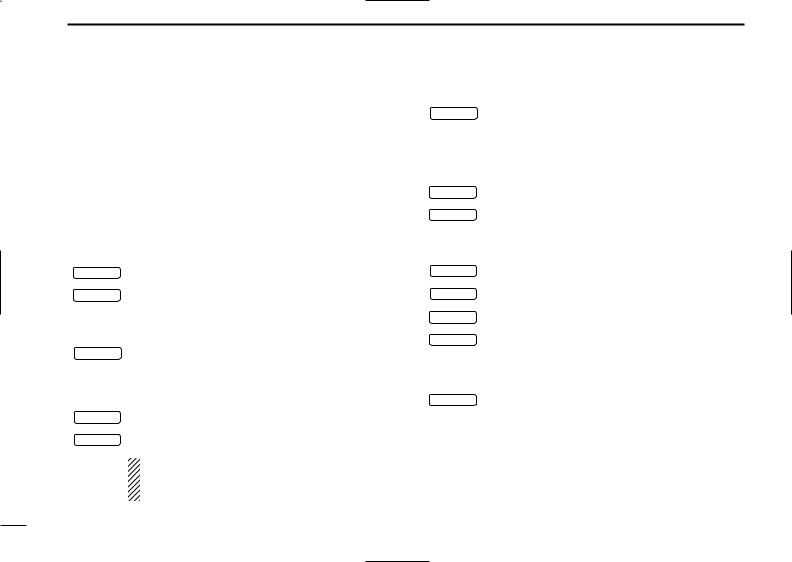
■Programmable function keys
The following functions can be assigned to [P0], [P1], [P2] and [P3] programmable function keys.
Consult your Icom Dealer or System operator for details concerning your transceiver’s programming.
In the following explanations, programmable function names are bracketed. The specific switch used to activate the function depends on programming.
¡CH UP AND DOWN KEYS
CH UP Select an operating channel.
CH DN
¡ BANK KEY
BANK |
Select and determine a bank number. |
¡ SCAN START/STOP KEY |
|
SCAN A |
Push this key to start scanning; and push again |
SCAN B |
to stop. |
|
|
NOTE: Place the microphone on hook to start scanning.
Take the microphone off hook to stop scanning.
¡ SCAN TAG KEY
TAG |
Adds or deletes the selected channel to the scan |
|
group. |
¡ PRIORITY CHANNEL KEYS |
|
PRI A |
Push these keys to select priority A or priority B |
PRI B |
channel, respectively. |
|
|
¡ OPERATING CHANNEL KEYS |
|
CH1 |
Select an operating channel directly. |
CH2 |
|
CH3 |
|
CH4 |
|
¡ LOCK KEY |
|
LOCK |
Push this key for 1 sec. to lock all programmable |
keys except the following:
• [CALL] (incl. [CAL A] and [CAL B]), [MONI] and [EMER] keys.
3
 Loading...