


IC-A110

INSTRUCTION MANUAL
VHF AIR BAND TRANSCEIVER
iA110EURO
FOREWORD
WORD DEFINITION
RWARNING
Personal injury, re hazard or electric shock
may occur.
CAUTION
Equipment damage may occur.
NOTE
If disregarded, inconvenience only. No risk
of personal injury, re or electric shock.
CAUTIONS
READ ALL INSTRUCTIONS carefully and completely
before using the transceiver.
SAVE THIS INSTRUCTION MANUAL — This in-
struction manual contains important operating instructions for
the IC-A110EURO.
EXPLICIT DEFINITIONS
The explicit definitions below apply to this instruction manual.
i
Versions of the IC-A110EURO which display the
“CE” symbol on the serial number seal, comply with
the essential requirements of the 89/336/EEC directive for Electromagnetic Compatibility.
R WARNING! NEVER operate the transceiver with a
headset or other audio accessories at high volume levels.
Hearing experts advise against continuous high volume operation. If you experience a ringing in your ears, reduce the
volume level or discontinue use.
NEVER connect the transceiver to an AC outlet or to a
power source of more than 32 V DC. Such a connection will
damage the transceiver.
NEVER connect the transceiver to a power source that is
DC fused at more than 5 A. Accidental reverse connection will
be protected by this fuse, higher fuse values will not give any
protection against such accidents and the transceiver will be
ruined.
DO NOT operate the transceiver near unshielded electrical
blasting caps or in an explosive atmosphere.
DO NOT connect the transceiver to a power source using
reverse polarity. This connection will not only blow fuses but
also may damage the transceiver.

TABLE OF CONTENTS
DO NOT place unit in a non-secure place to avoid inad-
vertent use by children.
DO NOT push the PTT when not actually desiring to trans-
mit.
AVOID using or placing the transceiver in direct sunlight or
in areas with temperatures below –30°C (–22°F) or above
+60°C (+140°F).
AVOID placing the transceiver in excessively dusty envi-
ronments.
AVOID placing the transceiver against walls. This will ob-
struct heat dissipation.
AVOID the use of chemical agents such as benzine or al-
cohol when cleaning, as they damage the transceiver surfaces.
BE CAREFUL! The transceiver will become hot when
operating continuously for long periods.
FOREWORD ........................................................................................... i
EXPLICIT DEFINITIONS ......................................................................... i
CAUTIONS .............................................................................................. i
TABLE OF CONTENTS .......................................................................... ii
1 PANEL DESCRIPTION ............................................................... 1 – 3
■ Panel description ............................................................................. 1 – 2
■ Function display .................................................................................... 3
2 BASIC OPERATION ................................................................... 4 – 5
■ Power ON ............................................................................................. 4
■ Channel selection .................................................................................. 4
■ Squelch function .................................................................................... 5
■ Side tone function.................................................................................. 5
■ LCD backlight control ............................................................................ 5
■ Dial select function ................................................................................ 5
3 SCAN OPERATION ................................................................... 6 – 7
■ Scan operation ..................................................................................... 6
■ On-hook scan ....................................................................................... 7
■ Dualwatch ............................................................................................. 7
4 MEMORY PROGRAMMING ...................................................... 8 –9
■ Programming a memory channel .......................................................... 8
■ Memory names...................................................................................... 9
5 OTHER FUNCTIONS ............................................................... 10-11
■ Initial set mode ............................................................................... 10-11
6 CONNECTION AND INSTALLATION .................................... 12 – 13
■ Rear panel and connections ............................................................... 12
■ Mounting ............................................................................................. 13
■ Supplied accessories........................................................................... 13
7 CLONING ...................................................................................... 14
8 SPECIFICATIONS ............................................................. 15-17
9 OPC-871 HEADSET ADAPTER/OTHER OPTIONS.......... 18-19
■ OPC-871 Headset adapter .................................................................. 18
■ Other Options ...................................................................................... 19
ii
1
V/M
SCAN
PRI SQL
!0
q
we
r
tyu
io
PANEL DESCRIPTION
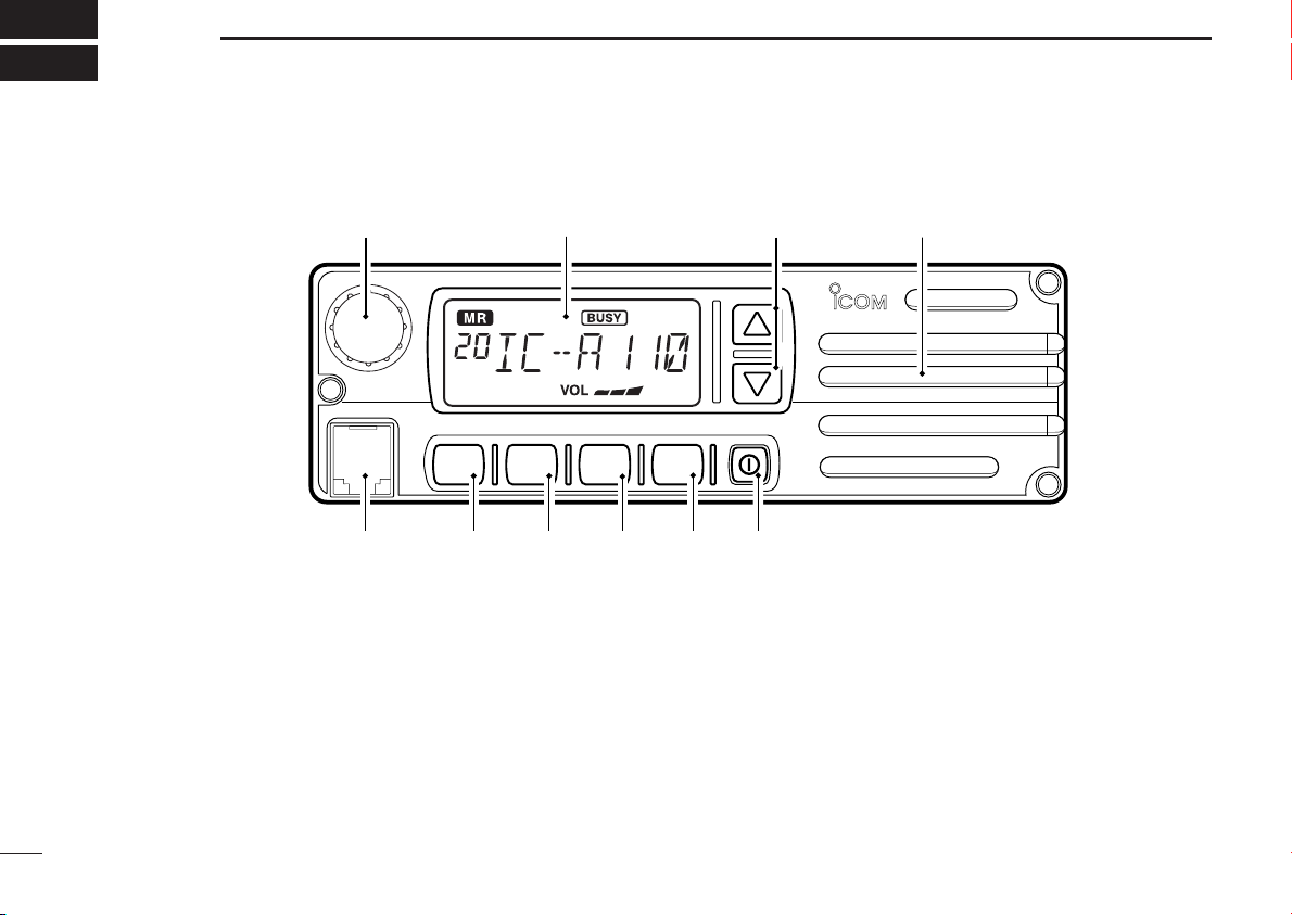
■ Panel description
q TUNING [DIAL(TS)]
➥ Changes the operating frequency; memory channel in
memory mode; set mode contents in set mode, etc.
➥ Push to toggle the dimmer control OFF, Low and High.
➥ Push and hold for 1 sec. to select the Tuning Step [TS];
1 MHz or 10 kHz are available. (p. 5)
w FUNCTION DISPLAY (p. 3)
Displays the operating frequency, memory channel name, etc.
1
e VOLUME UP [Y] DOWN [Z] KEY
Adjusts the audio output level.
r LOUD SPEAKER
Front mounted loud speaker.
t POWER SWITCH [POWER]
Push and hold 500 m sec. to turn the power ON and OFF.
➥ The following functions are available at power ON as options:
• Initial set mode (p. 10)
• Cloning mode (p. 14)

PANEL DESCRIPTION
1
y SQL SWITCH [SQL]
➥ Push to turn on the squelch adjust mode. (p. 6)
➥ Push and hold this switch for 1 sec. to turn ON/OFF the
both internal and external speaker output. (p. 4)
u PRIORITY SWITCH [PRI]
➥ Push to select priority channel. (p. 11)
•“Pr” appears on the display.
i SCAN SWITCH [SCAN]
➥ Starts and stops the scan function:
• VFO mode: VFO scan function.
• Memory mode: Memory channel scan function. (p. 6)
➥ Push and hold this switch for 5 sec. to set the displayed
channel as a memory lock-out channel. (p. 8)
•“LOCK OUT” appears on the display.
o VFO/MEMORY SWITCH [V/M]/[MW]
➥ Push to toggle the VFO mode or the Memory mode. (p. 4)
• “X” and memory channel number appear when memory mode
is selected.
• The transceiver has 20 memory channels.
➥When VFO mode is selected;
•Push and hold this switch for 5 sec. to program the VFO frequency to memory channel. (p. 8)
➥When Memory mode is selected;
•
Push and hold this switch for 5 sec. to turn the “Memory name
write mode” ON.
!0 MICROPHONE CONNECTOR
Connects the supplied microphone or optional.
NEVER connect other microphones. The pin assignments
may be different and the transceiver may be damaged.
MICROPHONE
The supplied microphone has a PTT switch and a cradle. The
following functions are available when the microphone is
taken off from the hook or put back on hook:
➥ Automatic scan starts when putting on hook. (p. 7)
➥ Automatic scan stops when taken off hook. (p. 7)
NOTE: Optional functions vary with transceiver version.
In this manual, optional functions are indicated by
“”Icon.
Please contact your dealer for details.
2
PANEL DESCRIPTION
1
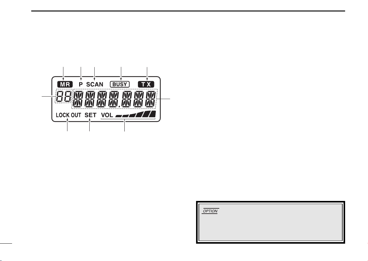
■ Function display
wq rt
e
!1
o
q MEMORY MODE INDICATOR (p. 5)
Appears when memory mode is selected.
w DUALWATCH INDICATOR (p. 7)
Indicates when the dualwatch function is activated.
e SCAN INDICATOR (p. 8)
Indicates when the scan function is selected.
r BUSY INDICATOR (p. 6)
“BUSY” appears when receiving a signal or when the
squelch is open. (p. 6)
i
u
y
t TX INDICATOR (p. 5)
Appears while transmitting.
y FREQUENCY DISPLAY (p. 11)
➥Shows the operating frequency.
➥Shows the channel name when the memory name function
is selected. (p. 10)
u VOLUME LEVEL INDICATORS
➥ Shows the AF volume level(while receiving).
i SET MODE INDICATOR
➥ Appears when the Initial set mode is selected. (p. 12)
!0 LOCK OUT INDICATOR
➥ Appears when the channel is set as a ‘LOCK OUT’ chan-
nel. (p. 10)
!1 MEMORY CHANNEL INDICATOR
➥ Indicates the selected memory channel number
➥ ‘Pr’ appears when the priority channel is selected.
*NOTE: The VFO/memory switch [V/M] and the memory
write switch [M/W] functions may not be available depending on version.
3
BASIC OPERATION
2
■ Power ON
q Push [POWER] to turn power ON.
w Operate the transceiver as indicated in the following sec-
tions.
e Select the desired memory channel (or VFO frequency)
with the [V/M] keys.
• When receiving a signal, appears and audio is emit-
ted from the speaker.
•Further adjustment of audio level may be necessary at this point.
• Push [SQL] to adjust the squelch level. (p. 6)
• Push and hold the tuning dial for 1 sec. to select the [TS], each
push increments/decrements to the frequency are either 10 kHz
or 1 MHz. (p. 7)
r Push and hold [PTT] to transmit, then speak into the mi-
crophone.
• Transmit indicator lights.
t Release [PTT] to receive.
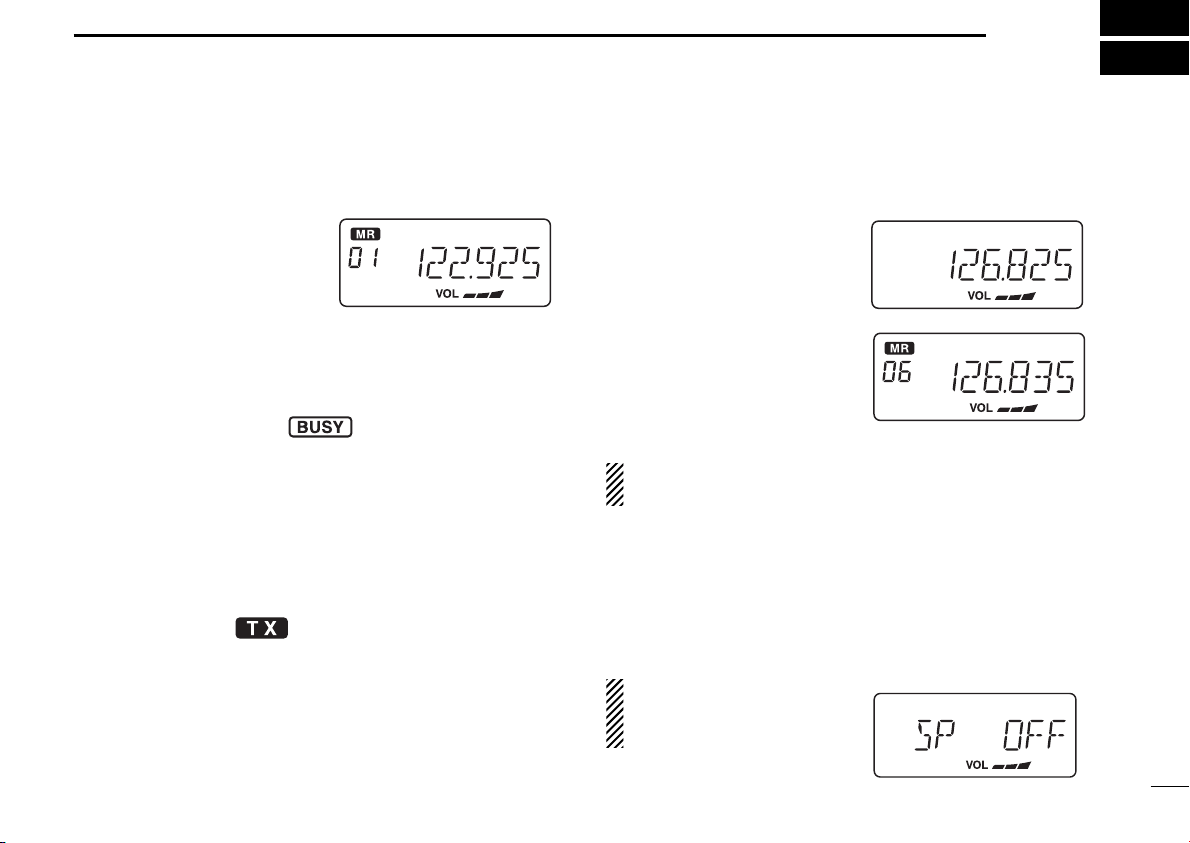
■ Channel selection
ï VFO/Memory selection
q Push [V/M] to select memory
mode or VFO mode.
➥ Rotate the dial to select a de-
sired frequency/channel.
w During memory mode opera-
tion, push [V/M] key to transfer the memory contents to
VFO.
• Push [V/M] to select VFO
mode.
NOTE: Only frequency data is transferred even if the
memory channel has a memory name.
ï External speaker output control
External speaker output can be turned OFF, if desired.
q Push and hold [SQL] for 1 sec.
w Rotate the dial to select “SP OFF”.
e Push [SQL] to turn to the previous mode.
NOTE: This function available both internal and external speakers.
4
BASIC OPERATION
2
■ Squelch function
The transceiver has a noise squelch circuit to mute undesired
noise while receiving no signal.
D Setting the squelch level
q Push [SQL] to turn the level adjusting mode ON.
w Turn the tuning [DIAL] to select the squelch level.
• ‘SQ 01’ is loose squelch and ‘SQ 25’ is tight squelch. (Ini-
tial level is ‘SQ 01’)
• ‘SQ 01’ indicates that the squelch circuit is turned off.
• “” appears on the display.
e Push [SQL] to return to regular operation.
■ Side tone function
When using an optional headset, such as those from the
David Clark Co. via the OPC-871
transceiver outputs your transmitted voice to the headset for
monitoring. (p. 17)
HEAD SET ADAPTOR, the
■ LCD backlight control
The backlight of the can be set OFF, Low or High.
➥ Push [DIAL] to toggle the backlight control; OFF, Low or
High are available.
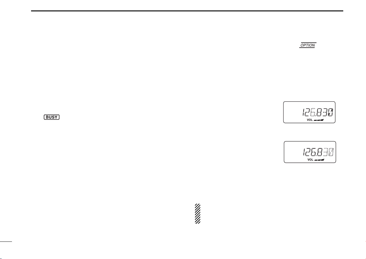
■ Dial select function
Use the dial select function to adjust the tuning behaviour of
the [DIAL] keys—use 1 MHz tuning when you want to change
the frequency in large increments; use regular tuning (25 kHz
or 8.33 kHz) when you want to change the frequency in
smaller increments.
q Push [V/M] to select VFO
mode.
w Push and hold [DIAL(TS)] for
1 sec. to select the desired
tuning increment.
• 1 MHz tuning or regular
tuning steps can be selected. (see diagrams at
right)
e Push and hold [DIAL(TS)] for
1 sec. to return to normal operation.
NOTE: Large tuning steps should be used only when you
want to change the frequency in large increments. Please
select regular tuning steps for normal operation.
1 MHz tuning selected
Regular tuning selected
5
 Loading...