


INSTRUCTION MANUAL
HF ALL BAND TRANSCEIVER
i718

IMPORTANT
READ THIS INSTRUCTION MANUAL CAREFULLY before attempting to operate the
transceiver.
SAVE THIS INSTRUCTION MANUAL. This manual contains important safety and operating
instructions for the IC-718.
EXPLICIT DEFINITIONS
WORD
RWARNING
CAUTION
NOTE
DEFINITION
Personal injury, fire hazard or electric shock may occur.
Equipment damage may occur.
Inconvenience only.
No risk of personal injury, fire or electric shock.
PRECAUTIONS
R WARNING HIGH VOLTAGE! NEVER attach an antenna or internal antenna connector
during transmission. This may result in an electric shock or burn.
R NEVER apply AC to the [DC13.8V] jack on the transceiver rear panel. This could cause a fire or ruin
the transceiver.
R NEVER apply more than 16 V DC, such as a 24 V battery, to the [DC13.8V] jack on the transceiver
rear panel. This could cause a fire or ruin the transceiver.
R NEVER let metal, wire or other objects touch any internal part or connectors on the rear panel of
the transceiver. This may result in an electric shock.
NEVER expose the transceiver to rain, snow or any liquids.
AVOID using or placing the transceiver in areas with temperatures below –10°C (+14°F) or above +60°C (+140°F). Be aware that temperatures on a vehicle’ s dashboard can exceed 80°C (+176°F), resulting in permanent damage to the transceiver if left there for extended periods.
AVOID placing the transceiver in excessively dusty environments or in direct sunlight.
AVOID placing the transceiver against walls or putting anything on top of the transceiver. This will obstruct heat dissipation.
During mobile operation, DO NOT operate the transceiver without running the vehicle’s engine. When transceiver power is ON and your vehicle’s engine is OFF, the vehicle’s battery will soon become exhausted.
Make sure the transceiver power is OFF before starting the vehicle. This will avoid possible damage to the transceiver by ignition voltage spikes.
During maritime mobile operation, keep the transceiver and microphone as far away as possible from the magnetic navigation compass to prevent erroneous indications.
BE CAREFUL! The heatsink will become hot when operating the transceiver continuously for long periods.
BE CAREFUL! If a linear amplifier is connected, set the transceiver’s RF output power to less than the linear amplifier’s maximum input level, otherwise, the linear amplifier will be damaged.
Use Icom microphones only (supplied or optional). Other manufacturer’s microphones have different pin assignments, and connection to the IC-718 may damage the transceiver.
i

TABLE OF CONTENTS 1
IMPORTANT ............................................................. |
i |
EXPLICIT DEFINITIONS .......................................... |
i |
PRECAUTIONS ........................................................ |
i |
1 TABLE OF CONTENTS ....................................... |
1 |
SUPPLIED ACCESSORIES .................................... |
1 |
2 PANEL DESCRIPTION .................................... |
2–8 |
n Front panel ........................................................ |
2 |
n Function display ................................................ |
5 |
n Rear panel ........................................................ |
6 |
n Microphone (HM-36) ......................................... |
8 |
3 INSTALLATION AND CONNECTIONS ......... |
9–14 |
n Unpacking ......................................................... |
9 |
n Selecting a location ........................................... |
9 |
n Grounding ......................................................... |
9 |
n Antenna connection .......................................... |
9 |
n Required connections ..................................... |
10 |
n Advanced connections .................................... |
11 |
n Power supply connections .............................. |
12 |
n Liner amplifier connections ............................. |
13 |
n External antenna tuners .................................. |
14 |
4 FREQUENCY SETTING .............................. |
15–19 |
n When first applying power ............................... |
15 |
n Initial setting .................................................... |
15 |
n VFO description .............................................. |
16 |
n Frequency setting ........................................... |
17 |
n Dial lock function ............................................. |
19 |
5 RECEIVE AND TRANSMIT ......................... |
20–34 |
n Mode selection ................................................ |
20 |
n Squelch and RF gain ...................................... |
20 |
n Function for receive ........................................ |
21 |
n DSP function (option) ...................................... |
23 |
n Filter selection ................................................. |
24 |
n Filter setting .................................................... |
25 |
n Function for transmit ....................................... |
26 |
n Split frequency operation ................................ |
30 |
n SWR ................................................................ |
30 |
n Function for CW .............................................. |
31 |
n Function for RTTY ........................................... |
33 |
SUPPLIED ACCESSORIES
The transceiver comes with the following accessories. |
|
|
Qty. |
q DC power cable.................................................... |
1 |
w Hand microphone (HM-36) .................................. |
1 |
e Fuse (FGB 20 A; for DC cable) ........................... |
1 |
r Fuse (FGB 4 A; internal use) ............................... |
1 |
6 MEMORY OPERATION ............................... |
35–38 |
n Memory channels ............................................ |
35 |
n Memory channel selection .............................. |
35 |
n Memory channel programming ....................... |
36 |
n Frequency transferring .................................... |
37 |
n Memory clearing ............................................. |
38 |
7 SCANS ......................................................... |
39–40 |
n Scan types ...................................................... |
39 |
n Preparation ..................................................... |
39 |
n Programmed scan operation ........................... |
40 |
n Memory scan operation .................................. |
40 |
8 SET MODE ................................................... |
41–47 |
n General ........................................................... |
41 |
n Quick set mode items ................................ |
42-43 |
n Initial set mode items ................................. |
44-47 |
9 INSTALLATION AND CONNECTIONS ....... |
48–51 |
n Opening the transceiver’s case ....................... |
48 |
n Optional bracket and carrying handle.............. |
48 |
n CR-338 HIGH STABILITY CRYSTAL UNIT ......... |
49 |
n UT-102 VOICE SYNTHESIZER UNIT ................. |
49 |
n UT-106 DSP RECEIVE UNIT ............................. |
50 |
n Optional IF filters ............................................. |
50 |
n AT-180 internal switch description .................. |
51 |
10 MAINTENANCE ........................................ |
52–53 |
n Troubleshooting .............................................. |
52 |
n Fuse replacement ........................................... |
53 |
n Resetting the CPU .......................................... |
53 |
11 SPECIFICATIONS ........................................... |
54 |
12 OPTIONS ................................................... |
55–56 |
13 CONTROL COMMAND ............................. |
57–58 |
n Remote jack (CI-V) information ....................... |
57 |
14 INTERNAL VIEWS .......................................... |
59 |
n Top view .......................................................... |
59 |
n Bottom view .................................................... |
59 |
15 INSTALLATION NOTES ................................. |
60 |
n DECLARATION OF CONFORMITY ............... |
61 |
q
w
e r
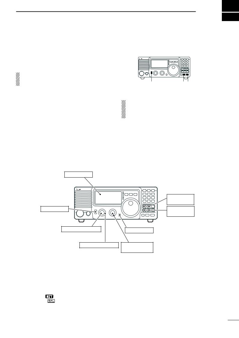
2 PANEL DESCRIPTION
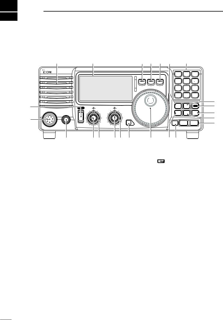
n Front panel
Speaker |
Function Display |
@1 |
@0 !9 !8 |
!7 |
|
|
||
|
|
|
|
|||||
IC-718 |
|
|
|
V/M 1 |
A=B2 |
A/B 3 |
||
|
|
|
|
|||||
|
|
MODE |
FIL |
TS |
|
|
|
|
|
|
|
|
MW 4 |
M-CL 5 |
M V 6 |
||
|
|
|
|
SPL |
SCN |
8 |
VOX |
9 |
|
|
|
|
7 |
|
|
||
|
|
|
|
NR . |
ANF 0 |
F-INP |
||
|
|
|
|
ENT |
||||
q |
|
|
|
|
|
|
|
|
|
|
! |
PWR |
AF |
RF/SQL |
RIT |
SHIFT |
|
|
NB |
COMP |
SET |
! |
|
|
|
|
|
|
|
|
|||||
|
MIC |
|
|
|
|
|
|
|
|
|
|
|
PHONES |
|
|
|
|
|
|
P.AMP |
ATT |
TUNER |
! |
w |
|
|
|
|
|
LOCK |
|
|
|
|
! |
|
|
|
|
|
|
|
|
|
|
|
|
|
|
|
|
|
|
|
|
CH |
ZDN |
UP Y |
! |
|
e |
|
r t |
|
y u |
i |
o |
!0!1 |
|
|
|
q POWER SWITCH [PWR]
Push momentarily to turn power ON.
• Turn the optional DC power supply ON in advance.
Push for 1 sec. to turn power OFF.
While pushing and holding [SET], push [PWR] to enter the initial set mode. (p. 41)
w MICROPHONE CONNECTOR [MIC]
Accepts supplied or optional microphone.
•See p. 55 for appropriate microphones.
•See p. 8 for microphone connector information.
e HEADPHONE JACK [PHONES] (p. 11)
Accepts headphones (8 Ω).
•When headphones are connected, the internal speaker or connected external speaker does not function.
r AF CONTROL [AF] (inner control)
Varies the audio output level from the speaker.
t RF GAIN/SQUELCH CONTROL [RF/SQL]
(outer control; pgs. 20, 44)
Adjusts the squelch threshold level. The squelch removes noise output from the speaker (closed condition) when no signal is received.
•The squelch is available for all modes.
•The control can be set as the squelch plus RF gain controls or squelch control only (RF gain is fixed at maximum) in initial set mode.
y RIT CONTROLS [RIT] (Inner control; p. 21)
Shifts the receive frequency without changing the transmit frequency.
• Rotate the control clockwise to incerase the frequency,
or rotate the control counterclockwise to decrease the frequency. “ RIT


 ” appears on the display.
• The shift frequency range is ±1.2 kHz.
u IF SHIFT CONTROLS [SHIFT] (Outer control; p. 21)
Shifts the center frequency of the receivers’s IF pass-band.
•Rotate the control colckwise to shift the center frequency higher, or rotate the control counterclockwise to shift the center frequency lower.
iLOCK SWITCH [LOCK] (p. 19)
Push momentarily to turn the dial lock function ON and OFF.
•The dial lock function electronically locks the main dial.
•When the optional UT-102 VOICE SYNTHESIZER UNIT is installed (p. 49), push for 1 sec. to have the frequency, etc. announced.
•UT-102 operation can be adjusted in initial set mode (p. 46).
o MAIN DIAL
Changes the displayed frequency, selects quick/ initial set mode items, etc.
!0PREAMP SWITCH [P.AMP] (p. 21)
Push momentarily to turn the preamp ON or OFF.
!1CH SWITCH [CH] (p. 35)
Push momentarily to turn the memory channel select function ON or OFF.
•[MEMO] blinks while memory channel select function is turned on.

•Push several times (or push and hold) [√ DN]/[UP ∫] until desired memory channel appears.
•After pushing [F-INP/ENT], push desired memory channel number from the keypad, then push [FINP/ ENT] again to select the memory channel directory.
•Push [CH] to exit the memory channel select function.
!2MEMORY CHANNEL (BAND) UP/DOWN
SWITCHES [√ DN]/[UP ∫] (p. 35)
Push one or more times to select the memory channel, while [MEMO] indicator is blinking.
Push to select a band.
Push to select the quick/initial set mode items while quick/initial set mode is selected.
!3ATTENUATOR SWITCH [ATT] (p. 22)
Push to toggle the 20 dB attenuator function ON and OFF.
!4TUNER SWITCH [TUNER] (pgs. 28, 29)
Push momentarily to toggle the automatic antenna tuner function ON/OFF.
•An optional antenna tuner must be connected.
Push for 1 sec. to manually tune the tuner.
•An optional antenna tuner must be connected.
•When the tuner cannot tune the antenna, the tuning circuit is bypassed automatically after 20 sec.
!5SET SWITCH [SET]
Push for 1 sec. to enter the quick set mode. (p. 41)
Pushing and holding [SET], and then push [POWER] to enter the initial set mode. (p. 41)
Push to toggle the meter function; (p. 26)
•PO: indicates the relative RF output power.
•ALC: Indicates ALC level.
•SWR: indicates the SWR over the transmission line.
!6MIC COMPRESSOR SWITCH [COMP] (p. 27) Toggles the Mic. compressor function ON and OFF.
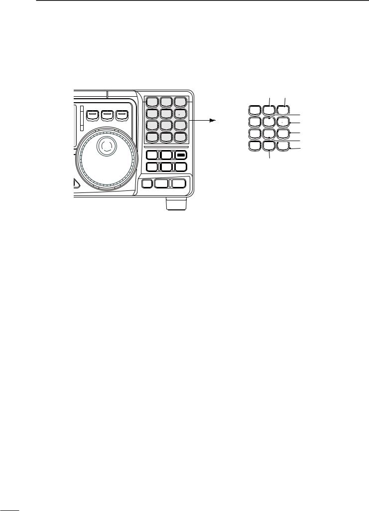
!7KEYPAD
The keypad can be used for several functions as discribed below:
•[F-INP/ENT], keypad then [F-INP/ENT].
—Direct frequency input. (pgs. 4, 7)
•[CH], [F-INP/ENT], keypad then [F-INP/ENT] then [V/M]
—Memory channel selection. (pgs. 4, 35)
•[V/M], [A=B], [A/B], [MW], [M-CL], [M≈V], [SPL], [SCAN], [VOX], [NR] (option) and [ANF] (option) switch. (p. 4)
!8NOISE BLANKER SWITCH [NB] (p. 22)
Toggles the noise blanker ON and OFF. The noise blanker reduces pulse-type noise such as that generated by automobile ignition systems. This function is not effective against non pulsetype noise.
PANEL DESCRIPTION 2
Push [NB] for 1 sec to enter the noise blanker level setting condition.
!9QUICK TUNING STEP SWITCH [TS] (pgs. 18, 19)
Selects a quick tuning step or turns the quick tuning step OFF.
•While the quick tuning indicator ( ) is displayed, the frequency can be changed in kHz step.
While the quick tuning step is OFF, it turns the 1 Hz step ON and OFF when pushed for 1 sec.
•1 Hz indication appears and the frequency can be changed in 1 Hz steps.
While the kHz quick tuning step is selected, it enters tuning step set mode when pushed for 1 sec.
@0FILTER SWITCH [FIL] (p. 24)
Push momentarily to toggle between the preprogrammed normal, wide and narrow IF filters for the selected operating mode.
@1MODE SWITCHES [LSB/USB]/[CW/CW-R]/ [RTTY/RTTY-R]/[AM] (p. 20)
Push to toggle an operating mode.
•Push[MODE] for 1 sec. during SSB mode to toggle between LSB or USB.
•Push [MODE] for 2 sec. during CW or RTTY mode, to toggle between CW and CW reverse or RTTY and RTTY reverse. “ ” appears on the display.
2 PANEL DESCRIPTION
n Front panel (continued)
V/M 1 |
A=B2 |
A/B 3 |
||
MODE FILTER TS |
|
|
|
|
MW 4 |
M=CL 5 |
M V 6 |
||
7 |
|
8 |
|
9 |
SPL |
SCN |
|
VOX |
|
NR . |
ANF 0 |
F-INP |
||
ENT |
||||
NB |
COMP |
SET |
||
P.AMP |
ATT |
TUNER |
||
K |
|
|
|
|
CH ZDN |
|
UP Y |
||
@2 V/M 1
V/M 1
@3 MW 4
MW 4
@4 SPL7
SPL7
@5 NR .
NR .
#3 #2 |
|
||||
A=B |
2 |
A/B |
3 |
#1 |
|
|
|
|
|||
M=CL 5 |
M V 6 |
#0 |
|||
SCN8 |
VOX 9 |
@9 |
|||
ANF 0 |
F-INP |
@8 |
|||
@7 |
|||||
ENT |
|||||
@6
@2VFO/MEMORY SWITCH/1 [V/M•1] (pgs. 16, 35)
Toggles the operating mode between VFO mode or memory mode when pushed.
@3MEMORY WRITE SWITCH/4 [MW•4] (p. 36)
Stores the displayed frequency and operating mode into the selected memory channel when pushed for 1 sec.
@4SPLIT SWITCH/7 [SPL•7] (p. 30)
Turns the split frequency operation ON or OFF when pushed.
@5NR SWITCH/. [NR• . ] (p. 23)
Toggles the optional noise reduction function ON or OFF when pushed. Functions in all modes.
•An optional UT-106 DSP UNIT is required.
•[NR] appears on the display.
Enters noise reduction level set mode when pushed for 1 sec.
@6ANF SWITCH/0 [ANF•0] (p. 23)
Toggles the Automatic Notch Filter function ON or OFF. Functions in SSB and AM modes.
•An optional UT-106 DSP UNIT is required.
•[ANF] appears on the display.
@7FRQUENCY INPUT/ENTER SWITCH
[F-INP/ENT]
[F-INP/ENT], then keypad then [F-INP/ENT]
—Direct frequency input. (p. 17)
[CH] then [F-INP/ENT], then keypad then [F-INP/ENT]. Push [CH].
—Direct memory number selection. (p. 35)
@8SCAN SWITCH/8 [SCAN•8] (p. 39)
Push momentarily to start/stop the programmed scan in VFO mode.
Push momentarily to start/stop the memory scan in memory mode.
@9VOX SWITCH/9 [VOX•9] (p. 27)
Turn the VOX function ON or OFF when pushed in SSB modes.
#0M≈V SWITCH/6 [MV•6] (p. 37)
Transfers the memory contents to VFO when pushed for 1 sec.
#1MEMORY CLEAR SWITCH/5 [M=CL•5] (p. 38) Clears the selected readout memory channel contents when pushed for 1 sec. in memory mode.
• [BLANK] appears above the memory channel number.
#2VFO SELECT SWITCH/3 [A/B•3] (p. 16)
Toggles between VFO A or VFO B in VFO mode.
Toggles between transmission VFO and reception VFO during split operation.
#3VFO EQUALIZATION SWITCH/2 [A=B•2]
Equalize the frequency and operating mode of the two VFO’s.
•The VFO B frequency and operating mode are equalized with the VFO A frequency and operating mode.
|
|
PANEL DESCRIPTION 2 |
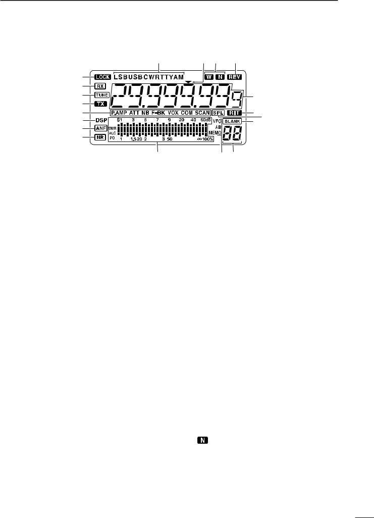
n Function display |
|
|
!9 |
!8!7 |
!6 |
q |
|
|
w |
|
|
e |
|
!5 |
r |
|
|
t |
|
!4 |
y |
|
!3 |
|
!2 |
|
u |
|
|
i |
|
|
o |
!0!1 |
|
q LOCK INDICATOR (p. 19) |
o SIGNAL/SQL/RF-GAIN METER |
|
Appears when the dial lock function is in use. |
Functions as an S-meter while receiving. |
|
w RECEIVE INDICATOR |
Functions as a Power, ALC or SWR meter while |
|
transmitting. (p. 26) |
||
Appears while receiving a signal or when the |
|
|
squelch is open. |
!0VFO/MEMORY INDICATOR (p. 16) |
|
e TUNE INDICATOR |
“VFO A” or “B” appears when VFO mode is |
|
selected. |
||
Appears while the automatic tuning function is |
“MEMO” appears when memory mode is selected. |
|
activated. |
|
|
r TRANSMIT INDICATOR |
!1MEMORY CHANNEL NUMBER READOUT (p. 35) |
|
Shows the selected memory channel number. |
||
Appears while transmitting. |
|
|
t FUNCTION INDICATORS |
!2BLANK INDICATOR (p. 38) |
|
Shows that the displayed memory channel is not |
||
“P.AMP” appears when antenna preamp is in |
programmed. |
|
use. |
• This indicator appears both in VFO and memory mode. |
|
“ATT” appears when the attenuator function is in |
!3SPLIT INDICATORS (p. 30) |
|
use. |
||
“NB” appears when the Noise Blanker function |
Appears when the split frequency operation is in |
|
is turned ON. |
use. |
|
“BK” appears when the semi break-in function is |
!4RIT INDICATOR (p. 21) |
|
selected in quick set mode. |
||
“F-BK” appears when the full break-in function |
Appears when the RIT function is in use. |
|
activates in CW mode. (p. 31) |
!5FREQUENCY READOUT |
|
“VOX” appears when the VOX function is |
||
selected in quick set mode. |
Shows the operating frequency. |
|
|
||
“COM” appears when the speech compressor |
!6REVERSE INDICATOR (p. 20) |
|
activates in SSB mode. |
||
Appears when the CW reverse or RTTY reverse |
||
“SCAN” appears when the scan function is |
||
mode is selected. |
||
activated. |
||
|
• Flashes when scan is paused.
y DSP UNIT INDICATOR
Appears when an optional UT-106 DSP unit is installed.
u AUTOMATIC NOTCH FILTER INDICATOR (p. 23) Appears when the optional Automatic Notch Filter function is in use.
i NOISE REDUCTION INDICATOR (p. 23) Appears when the optional Noise Reduction function is in use.
!7WIDE/NARROW FILTER INDICATORS (pgs. 24, 25)
“ ” appears when the wide IF filter is selected.
“ ” appears when the narrow IF filter is selected.
!8PROGRAMMABLE TUNING STEP INDICATORS
Appears when the programmable tuning step is selected.
!9MODE INDICATORS (p. 20)
Indicates the selected operating mode.
2 PANEL DESCRIPTION
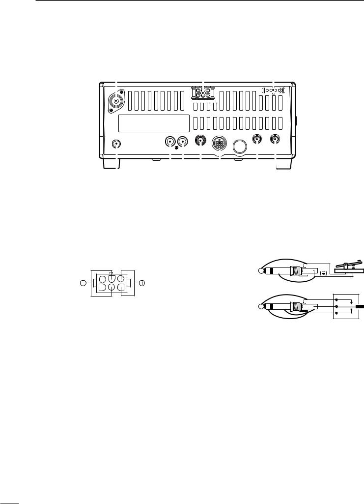
n Rear panel
q |
w |
e |
|||
|
|
|
|
|
|
|
|
|
|
|
|
|
|
|
|
|
|
|
|
|
|
|
|
|
|
|
|
|
|
|
|
|
|
|
|
|
|
|
|
|
|
|
|
!0 |
o i u y |
t r |
|||||||
q ANTENNA TERMINAL [ANT] (p. 10)
Connects a 50 Ω antenna with a PL-259 connector and a 50 Ω coaxial cable.
w DC POWER SOCKET [DC 13.8V] (p. 12)
Accepts 13.8V DC through the supplied DC power cable.
u ELECTRONIC KEYER JACK [KEY]
Accepts a paddle to activate the internal electronic keyer.
•Selection between the internal electronic keyer and straight key operation can be made in initial set mode.
When connecting |
( ) |
|
|
a straight key |
|
Rear panel view
e TUNER CONTROL SOCKET [TUNER] (p. 14) Accepts the control cable from an optional AH-4
AUTOMATIC ANTENNA TUNER.
r CI-V REMOTE CONTROL JACK [REMOTE] (p. 57) Designed for use with a personal computer for remote operation of transceiver functions.
t EXTERNAL SPEAKER JACK [EXT SP] (p. 11) Connects an 8 Ω external speaker, if desired.
•When an external speaker is connected, the internal speaker does not function.
y ACCESSORY SOCKET [ACC] (p. 7)
Enables connection to external equipment such as an optional AT-180 AUTOMATIC ANTENNA TUNER, a TNC for data communications or a liner amplifier, etc.
When connecting |
(dot) |
|
(com) |
||
a paddle |
||
(dash) |
||
|
i ALC INPUT JACK [ALC]
Connects to the ALC output jack of a non-Icom linear amplifier.
o SEND CONTROL JACK [SEND] (p. 14)
Goes to ground while transmitting to control external equipments such as a liner amplifier.
• Max. control level: 16 V DC/2 A
!0GROUND TERMINAL [GND] (p. 9)
Connects the terminal to ground.
PANEL DESCRIPTION 2
D ACC SOCKET INFORMATION
• ACC socket
|
|
|
|
|
|
|
|
|
|
|
|
|
|
|
|
ACC |
|
PIN # |
NAME |
|
DESCRIPTION |
SPECIFICATIONS |
COLOR |
|
|||||
|
|
|
|
|
|
|
|
|
|
|
|
|
|
|
|
|
|
|
1 |
8 V |
Regulated 8 V output. |
Output voltage |
: 8 V ±0.3 V |
brown |
|
||||
|
|
|
|
Output current |
: Less than 10 mA |
|
||||||||
|
|
|
|
|
|
|
|
|
|
|
||||
|
|
|
|
|
|
|
|
|
|
|
|
|
|
|
|
|
|
|
2 |
GND |
Connects to ground. |
|
|
|
|
red |
|
||
|
|
|
|
|
|
|
|
|
||||||
|
|
|
|
|
|
|
|
|
|
|
|
|
|
|
|
|
|
|
|
|
Input/output pin. |
Ground level |
|
: –0.5 V to 0.8 V |
|
|
|||
|
|
|
|
|
|
Goes to ground when transmitting. |
|
|
|
|||||
|
|
|
|
3 |
SEND |
Input current |
|
: Less than 20 mA |
orange |
|
||||
|
|
|
|
When grounded, transmits. |
|
|
||||||||
|
|
|
|
|
|
|
|
|
|
|
|
|||
|
|
|
|
|
|
|
|
|
|
|
|
|
|
|
|
|
|
|
4 |
BDT |
Data line for the optional AT-180. |
|
|
|
|
yellow |
|
||
|
|
|
|
|
|
|
|
|
||||||
|
|
|
|
|
|
|
|
|
|
|
|
|
|
|
|
|
|
|
5 |
BAND |
Band voltage output. |
Output voltage |
: 0 to 8.0 V |
green |
|
||||
|
|
|
|
(Varies with amateur band) |
|
|||||||||
|
|
|
|
|
|
|
|
|
|
|
|
|||
|
|
|
|
|
|
|
|
|
|
|
|
|
|
|
|
13 |
|
|
6 |
ALC |
ALC voltage input. |
Control voltage |
: –4 to 0 V |
blue |
|
||||
9 |
10 |
11 |
12 |
Input impedance |
: More than 10 kΩ |
|
||||||||
|
|
|
|
|
|
|
||||||||
5 |
6 |
7 |
8 |
|
|
|
|
|
|
|
|
|
|
|
1 |
2 |
3 |
4 |
7 |
NC |
|
|
|
|
|
|
|
purple |
|
Rear panel |
|
|
|
|
|
|
|
|
||||||
|
|
|
|
|
|
|
|
|
|
|
||||
|
|
|
|
|
|
|
|
|
|
|
||||
|
view |
|
8 |
13.8 V |
13.8 V output when power is ON. |
Output current |
: Max. 1 A |
gray |
|
|||||
|
|
|
|
|
||||||||||
|
|
|
|
|
|
|
|
|
|
|
|
|
|
|
|
|
|
|
9 |
TKEY |
Key line for the AT-180. |
|
|
|
|
white |
|
||
|
|
|
|
|
|
|
|
|
||||||
|
|
|
|
|
|
|
|
|
|
|
|
|
|
|
|
|
|
|
10 |
FSKK |
RTTY keying input. |
Ground level |
|
: –0.5 to 0.8 V |
black |
|
|||
|
|
|
|
Input current |
|
: Less than 10 mA |
|
|||||||
|
|
|
|
|
|
|
|
|
|
|
|
|||
|
|
|
|
|
|
|
|
|
|
|
|
|
|
|
|
|
|
|
|
|
|
|
|
Input impedance |
: 10 kΩ |
|
|
||
|
|
|
|
11 |
MOD |
Modulator input. |
Input level |
|
: Approx. 100 mV |
pink |
|
|||
|
|
|
|
|
|
|
|
|
|
|
|
rms |
|
|
|
|
|
|
|
|
|
|
|
|
|
|
|
|
|
|
|
|
|
12 |
AF |
AF detector output. |
Output impedance |
: 4.7 kΩ |
light |
|
||||
|
|
|
|
Fixed, regardless of [AF] position. |
Output level |
|
: 100 to 300 mV rms |
blue |
|
|||||
|
|
|
|
|
|
|
|
|||||||
|
|
|
|
|
|
|
|
|
|
|
|
|
|
|
|
|
|
|
13 |
SQLS |
Squelch output. |
SQL open |
: Less than 0.3 V/5 mA |
light |
|
||||
|
|
|
|
Goes to ground when squelch opens. |
SQL closed |
: More than 6.0 V/100 µA |
green |
|
||||||
|
|
|
|
|
|
|
||||||||
|
|
|
|
|
|
|
|
|
|
|
|
|
|
|
|
|
|
|
|
|
|
|
|
|
|
|
|
|
|
• When connecting the ACC conversion cable (OPC-599)
|
|
|
|
4 |
2 |
5 |
q FSKK |
t AF |
|
|
|
|
w GND |
y SQLS |
|||
|
|
|
|
1 |
|
3 |
||
|
|
|
|
8 |
e SEND |
u 13.8 V |
||
|
|
|
|
6 |
7 |
|||
|
|
|
|
|
r MOD |
i ALC |
||
|
13 |
|
|
|
|
|||
|
|
|
|
|
|
|
||
9 |
10 |
11 |
12 |
ACC 1 |
|
|
||
5 |
6 |
7 |
8 |
|
|
|||
|
|
|
|
|
||||
1 |
2 |
3 |
4 |
|
|
|
q 8 V |
t ALC |
|
|
|
|
4 |
2 |
5 |
||
|
|
|
|
1 |
|
3 |
w GND |
y NC |
|
|
|
|
|
e SEND |
u 13.8 V |
||
|
|
|
|
6 |
|
7 |
||
|
|
|
|
|
r BAND |
|
||
|
|
|
|
|
|
|
|
|
ACC 2
2 PANEL DESCRIPTION
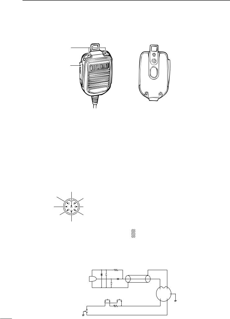
n Microphone (HM-36)
q
w
q UP/DOWN SWITCHES [UP]/[DN]
Change the selected readout frequency or memory channel.
•Continuous pushing changes the frequency or memory channel number continuously.
•The [UP]/[DN] switch can simulate a key paddle. Preset in the CW PADDL in initial set mode. (p. 31)
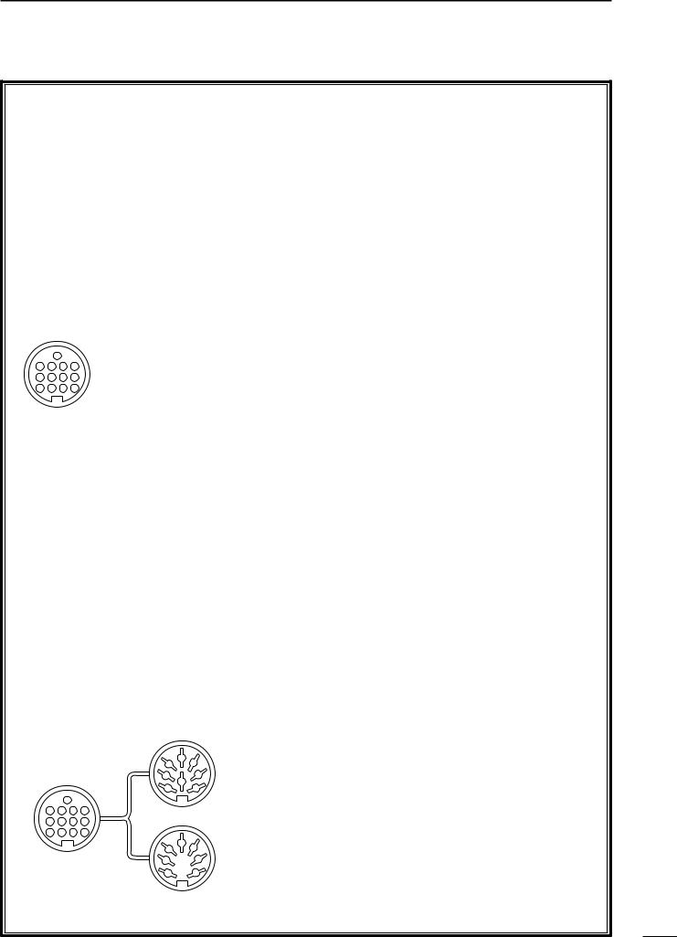
•MICROPHONE CONNECTOR
(Front view)
|
i Main readout AF output |
|
(varies with [AF]/[BAL]) |
q Microphone input |
u GND |
|
|
|
(Microphone ground) |
w +8 V DC output |
y GND (PTT ground) |
e Frequency up/down |
t PTT |
|
r Main readout squelch switch |
w PTT SWITCH
Push and hold to transmit; release to receive.
[MIC] |
FUNCTION |
DESCRIPTION |
|
PIN NO. |
|||
|
|
||
w |
+8 V DC output |
Max. 10 mA |
|
|
|
|
|
e |
Frequency up |
Ground |
|
|
|
||
Frequency down |
Ground through 470 Ω |
||
|
|||
|
|
|
|
r |
Squelch open |
“LOW” level |
|
|
|
||
Squelch closed |
“HIGH” level |
||
|
|||
|
|
|
CAUTION: DO NOT short pin 2 to ground as this can damage the internal 8 V regulator.
• HM-36 SCHEMATIC DIAGRAM
|
MICROPHONE |
MICROPHONE CABLE |
MICROPHONE PLUG |
|
|
10µ + 4700p 2k |
|
|
|
|
|
+ |
|
|
MIC |
|
0.33µ |
|
|
ELEMENT |
4700p |
|
|
|
|
|
|
||
|
|
|
q |
u |
|
|
|
w |
i y |
|
DOWN |
UP |
e r t |
|
PTT |
RECEIVE |
470 |
|
|
|
|
|
||
TRANSMIT
|
|
3 |
|
|
INSTALLATION AND CONNECTIONS |
|
|
|
|
||
|
|
||
n Unpacking |
n Antenna connection |
|
|
After unpacking, immediately report any damage to the delivering carrier or dealer. Keep the shipping cartons.
For a description and a diagram of accessory equipment included with the IC-718, see ‘Supplied accessories’ on p. 1 of this manual.
n Selecting a location
Select a location for the transceiver that allows adequate air circulation, free from extreme heat, cold, or vibrations, and away from TV sets, TV antenna elements, radios and other electro-magnetic sources.
The base of the transceiver has an adjustable stand for desktop use. Set the stand to one of two angles depending on your operating conditions.
n Grounding
To prevent electrical shock, television interference (TVI), broadcast interference (BCI) and other problems, ground the transceiver through the GROUND terminal on the rear panel.
For best results, connect a heavy gauge wire or strap to a long earth-sunk copper rod. Make the distance between the [GND] terminal and ground as short as possible.
 R WARNING: NEVER connect the
[GND] terminal to a gas or electric pipe, since the connection could cause an explosion or electric shock.
For radio communications, the antenna is of critical importance, along with output power and sensitivity. Select antenna(s), such as a well-matched 50 Ω antenna, and feedline. 1.5:1 or better of Voltage Standing Wave Ratio (VSWR) is recommended for your desired band. Of course, the transmission line should be a coaxial cable.
CAUTION: Protect your transceiver from lightning by using a lightning arrestor.
PL-259 CONNECTOR INSTALLATION EXAMPLE
q |
|
|
30 mm |
|
|
||||||
|
|
|
|
|
|
|
|||||
|
|
|
|
|
|
|
|
|
|
|
|
|
|
|
|
|
|
|
|
|
|
|
|
|
|
|
|
|
|
|
|
|
|
|
|
|
|
|
|
|
|
|
|
|
|
||
|
|
|
|
|
|
|
|
|
|
|
|
Coupling ring |
10 mm (soft solder) |
||||||||||
w |
10 mm |
|
Soft |
||||||||
|
|
|
|
|
|
|
|
||||
|
|
|
|
|
|
|
|
solder |
|||
|
|
|
|
|
|
|
|
|
|
|
|
|
|
|
|
|
|
|
|
|
|
||
|
|
|
|
|
|
|
|
|
|||
|
|
|
|
|
1–2 |
|
mm |
||||
Slide the coupling ring down. Strip the cable jacket and soft solder.
Strip the cable as shown at left. Soft solder the center conductor.
e |
solder |
solder |
|
|
|
|
Slide |
the |
connector |
||
|
|
||||
|
|
body on and solder it. |
|||
r |
|
Screw |
the |
coupling |
|
|
|
ring |
onto |
the |
|
|
|
connector body. |
|
||
30 mm ≈ 9⁄8 in 10 mm ≈ 3⁄8 in 1–2 mm ≈ 1⁄16 in
Antenna SWR
Each antenna is tuned for a specified frequency range and SWR may be increased out-of-range. When the SWR is higher than approx. 2.0:1, the transceiver’s power drops to protect the final transistor. In this case, an antenna tuner is useful to match the transceiver and antenna. Low SWR allows full power for transmitting even when using the antenna tuner. The IC-718 has an SWR meter to monitor the antenna SWR continuously.
3 INSTALLATION AND CONNECTIONS
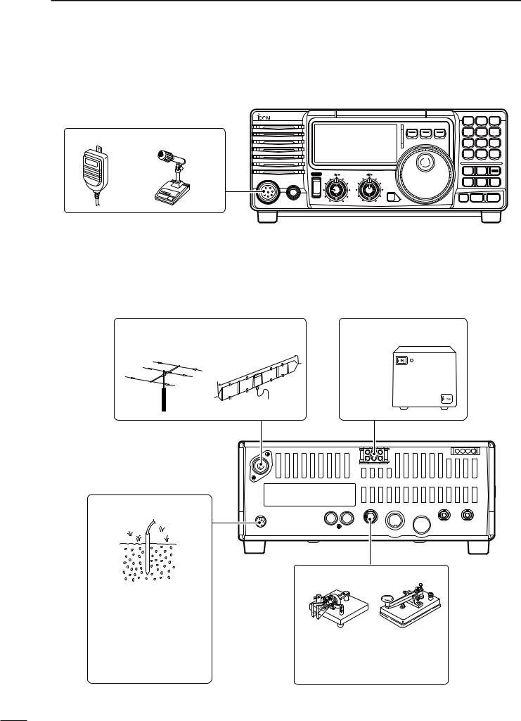
n Required connections
• Front panel
i718
MICROPHONES (p. 55)
|
PWR |
AF |
RF/SQL |
RIT |
SHIFT |
|
MIC |
|
|
|
|
|
PHONES |
|
|
|
|
|
|
|
|
|
LOCK |
HM-36 |
SM-20 |
|
|
|
|
|
V/M 1 |
A=B2 |
A/B 3 |
MODE FIL |
TS |
|
|
|
MW 4 |
M-CL 5 |
M V 6 |
|
SPL7 |
SCN8 |
VOX 9 |
|
NR . |
ANF 0 |
F-INP |
|
ENT |
||
|
NB |
COMP |
SET |
|
P.AMP |
ATT |
TUNER |
|
CH ZDN |
UP Y |
|
• Rear panel
ANTENNA (p. 56) |
|
|
|
|
|
|
DC POWER SUPPLY |
[Example]: 1.8–30 MHz bands |
|
|
AH-710 |
PS-85 |
|||
|
|
|
|||||
|
|
|
|
|
|
ft |
|
|
|
|
|
|
0.3 |
|
|
|
|
|
|
;8 |
|
|
|
|
|
|
.5 |
m |
|
|
|
|
|
24 |
|
|
|
|
|
|
x. |
|
|
|
|
|
|
ro |
|
|
|
|
|
|
|
app |
|
|
|
|
|
|
|
GROUND (p. 9)
Use the heaviest gauge wire or strap available and make the connection as short as possible.
Grounding prevents electrical shocks, TVI and other problems.
CW KEY
A straight key can be used when the internal electronic keyer is turned OFF in “CW PADDL” in initial set mode. (p. 31)
10
INSTALLATION AND CONNECTIONS 3
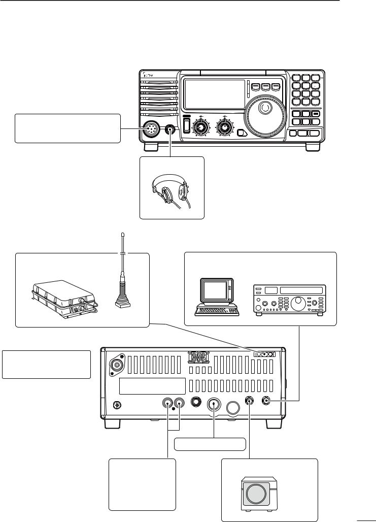
n Advanced connections
• Front panel
MIC
The AFSK modulation signal can be input from [MIC]. (p. 33)
IC-718
PWR |
AF |
RF/SQL |
RIT |
SHIFT |
MIC |
|
|
|
|
PHONES |
|
|
|
|
|
|
|
|
LOCK |
|
V/M 1 |
A=B2 |
A/B 3 |
MODE FIL |
TS |
|
|
|
MW 4 |
M-CL 5 |
M V 6 |
|
SPL7 |
SCN8 |
VOX 9 |
|
NR . |
ANF 0 |
F-INP |
|
ENT |
||
|
NB |
COMP |
SET |
|
P.AMP |
ATT |
TUNER |
|
CH |
ZDN |
UP Y |
HEADPHONES
• Rear panel
[REMOTE] (p. 57)
Used for computer control and transceive operation.
AH-4 (p. 55)
with
AH-2b or long wire
ANTENNA (p. 13)
Connects a liner amprifier, etc.
ACC SOCKETS (p. 7)
[SEND], [ALC]
(p. 14)
Used for connecting a non-Icom linear amplifier.
EXTERNAL SPEAKER (p. 55)
SP-21, etc
11
3 INSTALLATION AND CONNECTIONS
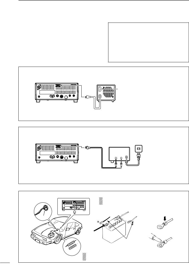
n Power supply connections
Use an optional PS-85 DC POWER SUPPLY when operating the IC-718 with AC power. Refer to the diagrams below.
CAUTION: Before connecting the DC power cable, check the following important items. Make
sure:
•The [POWER] switch is OFF.
•Output voltage of the power source is 12–15 V when you use a non-Icom power supply.
•DC power cable polarity is correct.
Red |
: positive + terminal |
Black |
: negative _ terminal |
CONNECTING PS-85 DC POWER SUPPLY
PS-85 |
DC power socket
DC power cable
Connect to an AC outlet using the supplied AC cable.
CONNECTING NON-ICOM DC POWER SUPPLY
|
DC power supply AC outlet |
DC power |
13.8 V 20 A |
|
|
socket |
_ + |
AC cable
_black
Supplied |
+red |
DC power cable |
20 A fuses |
CONNECTING A VEHICLE BATTERY
NEVER connect to |
NOTE: Use terminals for |
|
a 24 V battery. |
|
the cable connections. |
_ black |
+ red |
Crimp |
|
||
Grommet |
|
|
12 V |
Solder |
|
battery |
||
|
Supplied
DC power cable
Fuses
NEVER connect to a battery without supplied DC fuses, otherwise the fire hazard may occur.
12

INSTALLATION AND CONNECTIONS 3
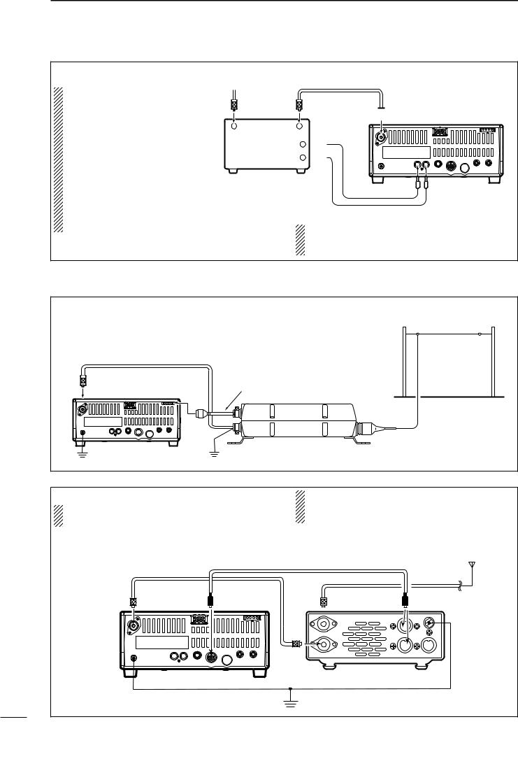
n Linear amplifier connections
CONNECTING THE IC-PW1
Remote control cable (supplied with the IC-PW1)
To an |
ACC cable (supplied with the IC-PW1) |
||
antenna ACC-1 |
|||
|
|
OPC-599 conversion cable |
|
ANT |
REMOTE |
(option) |
|
Coaxial cable |
|||
|
|
||
|
|
INPUT1 (supplied with the IC-PW1) |
|
|
ACC |
REMOTE |
EXCITER |
|
|
1 |
1&2 |
|
GND
13
9 10 11 12
5 6 7 8
1 2 3 4
GND
IC-PW1
AC outlet |
|
|
|
|
|
IC-718 |
|
|
|
Ground |
|||
|
|
|
||||
(Non-European versions : 100–120/220–240 V |
|
|||||
European version |
: 230 V) |
|
||||
CONNECTING THE IC-4KL
Coaxial cable (supplied with the IC-4KL)
ACC cable (supplied with the IC-4KL) |
To an |
|
antenna |
||
|
 OPC-599 conversion cable (option)
ANT |
ACC |
ACC
IC-4KL |
|
|
Remote |
IC-4KL |
|
controller |
||
|
IC-718
Remote control cable
|
(supplied with the IC-4KL) |
Ground |
AC outlet (220–240 V) |
13
3 INSTALLATION AND CONNECTIONS
CONNECTING A NON-ICOM LINER AMPLIFIER
R WARNING:
Set the transceiver output power and linear amplifier ALC output level referring t o t h e l i n e a r a m p l i f i e r instruction manual.
The ALC input level must be in the range 0 V to –4 V, and the transceiver does not accept positive voltage. Nonmatched ALC and RF power settings could cause a fire or ruin the linear amplifier.
To an |
antenna |
RF OUTPUT RF INPUT
SEND 
 ALC
ALC 

Non-Icom linear amplifier
50 Ω coaxial cable
 ANT IC-718
SEND ALC
The specifications for the SEND relay are 16 V DC 2 A. If this level is exceeded, a large external relay must be used.
n External antenna tuners
CONNECTING THE AH-4 (p. 29)
Long wire or optional AH-2b
Coaxial cable (from the AH-4)
 Control cable
IC-718 |
AH-4 |
Ground |
Ground |
CONNECTING THE AT-180 (p. 28)
DO NOT! connect AT-180 and AH-4 at the same time. Both tuners will not function correctly.
Turn the IC-718’s power OFF when connecting the AT-180, otherwise, the CPU may malfunction and the AT-180 may not function properly.
Coaxial cable supplied |
ACC cable supplied with the AT-180 |
HF |
|
with the AT-180 |
|
|
antenna |
[ANT] |
[ACC] |
AT-180 [ACC] |
one of two |
connectors |
|||
IC-718
13
9 10 11 12
5 6 7 8
1 2 3 4
Ground
14
FREQUENCY SETTING 4
n When first applying power (CPU resetting)
Before first applying power, make sure all connections required for your system are complete by referring to Chapter 3. Then, reset the transceiver using the following procedure.
Resetting CLEARS all programmed contents in memory channels and returns programmed values in quick/initial set mode to default values.
q Make sure the transceiver power is OFF.
w While pushing and holding [∫ UP] and [√ DN], push [PWR] for 1 sec. to turn power ON.
•The internal CPU is reset.
•The transceiver displays its initial VFO frequencies when resetting is complete.
e All quick/initial set mode settings are returned to default values. (p. 41)
[PWR] |
[Z] [Y] |
Under cooler temperatures, the LCD may appear dark and unstable after turning power ON. This is normal and does not indicate any equipment malfunction.
n Initial settings |
|
|
||
After resetting the transceiver, set controls and |
CCW : counterclockwise |
|||
switches as shown in the figure below. |
||||
|
||||
|
[METER]: Po |
|
||
|
|
|
[NB], [COMP]: |
|
|
|
|
OFF |
|
[POWER]: OFF |
|
[P.AMP], [ATT],: |
||
|
|
|
OFF |
|
|
[AF]: Max. CCW |
[LOCK]: OFF |
||
|
|
|
||
|
|
[RF/SQL]: 12 o'clock |
[RIT]: Center |
|
|
|
|
[IF SHIFT]: Center |
|
Turn power ON, then check the display. If any of the |
|
|||
following indicators appear, turn them OFF as follows: |
|
|||
• Quick tuning step indicator “Z” : Push [TS]. |
|
|||
• 1 Hz frequency readout |
: Push [TS] for 1 sec. |
|
||
|
|
(while quick tuning |
|
|
|
|
step is OFF) |
|
|
• RIT indicator “ |
RIT ” |
: Center. |
|
|
• Split indicator “ |
” |
: Push [SPL]. |
|
|
15
4 FREQUENCY SETTING
n VFO description
VFO is an abbreviation of Variable Frequency Oscillator, and traditionally refers to an oscillator.
The IC-718 VFO can store a frequency and an operating mode.
You can call up a desired frequency to the VFO with the keypad or the memory transfer function (see p. 37). You can also change the frequency with the tuning dial and select the operating mode with the [MODE] switch or call up previously accessed frequency and modes with the band stacking register (p. 18).
The IC-718 has two VFOs, specially suited for split frequency opration. The VFOs are called VFO A and VFO B. You can call up the desired VFO.
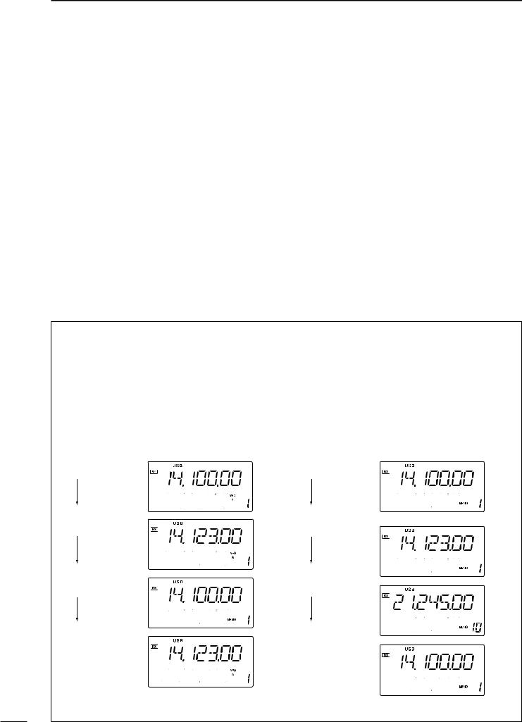
• Differences between VFO mode and memory mode
VFO MODE
Each VFO shows a frequency and operating mode. If the frequency or operating mode is changed, the VFO automatically memorizes the new frequency or new operating mode.
When the VFO is selected from another VFO or memory mode, the last-used frequency and operating mode for that VFO appears.
[EXAMPLE]
VFO is selected.
MEMORY MODE (pgs. 35–38)
Each memory channel shows a frequency and operating mode like a VFO. Even if the frequency or mode is changed, the memory channel does not memorize the new frequency or operating mode.
When the memory channel is selected from another memory channel or VFO mode, the memorized frequency and operating mode appear.
[EXAMPLE]
Memory channel 1 is selected.
The frequency |
The frequency |
is changed. |
is changed. |
Memory mode |
Another memory |
is selected. |
channel is selected. |
VFO is selected |
Memory channel 1 |
again. |
is selected again. |
Changed frequency (14.123 MHz) appears.
Changed frequency (14.123 MHz) does not appear and memorized frequency (14.100 MHz) appears instead.
16
FREQUENCY SETTING 4
n Frequency setting
D Using the tuning dial
q Push [∫ UP] or [√ DN] one or more times to select the desired ham band.
w Select the desired operating mode with the mode switch. (p. 20).
e Rotate the tuning dial to set the desired frequency
• For general coverage receiver use
The IC-718 has a general coverage receiver band. q Push [∫ UP] or [√ DN] one or more times to
select the general coverage receiver band.
Note: Even if you select the ham band, you can set the transceiver to the general coverage frequency. When the displayed frequency exits the transmit frequency range (ham band), a band edge beep may be emitted (depends on initial set mode programming).
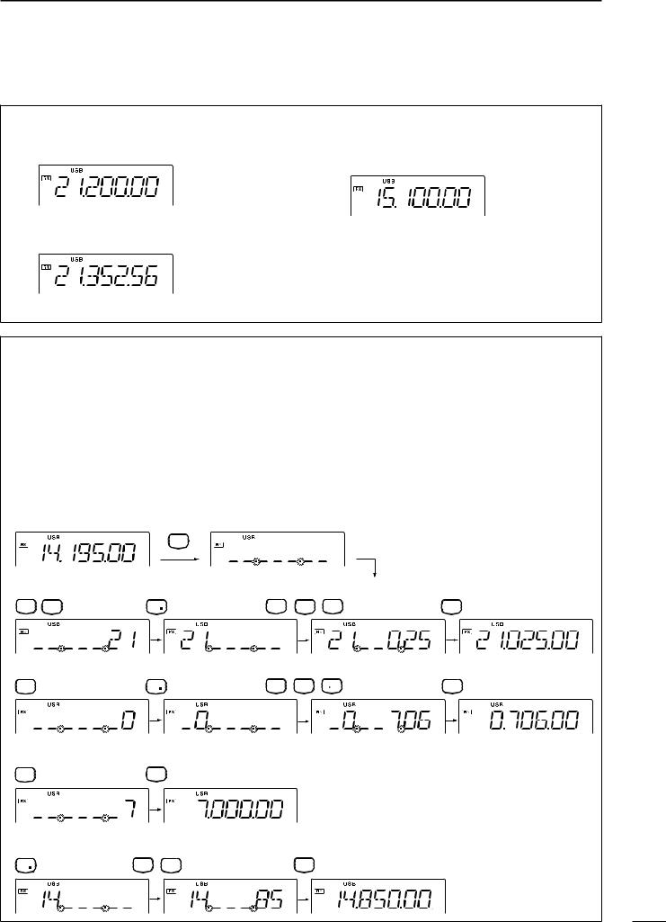
D Direct frequency entry with keypad
The transceiver has a keypad for direct frequency entry as described below.
q Push [F-INP/ENT], then push the numeral keys on the keypad to enter the MHz digits for the desired frequency.
•If a key is mistakenly pushed, push [SET] (or any key except keypad) and start again from the beginning.
•When entering the same MHz digits as the displayed frequency, this step can be skipped.
w Push [•] on the keypad.
e Push the numeral keys to enter the frequency digits below 1 MHz.
•If a key is mistakenly pushed, push [SET] (or any key except keypad) and start again from the beginning.
r Push [F-INP/ENT] to set the input frequency.
•When pushing [F-INP/ENT] after entering the MHz digits, zeros are automatically entered for the kHz digits.
[EXAMPLE]
•Start
F-INP
ENT
•To set to 21.025 MHz
A=B2 V/M 1 |
NR |
ANF 0 A=B2 M=CL 5 |
F-INP |
ENT |
•To set to 706 KHz (0.706 MHz)
ANF 0 |
NR |
SPL7 ANF 0 M V 6 |
F-INP |
ENT |
•To set to 7 MHz
SPL |
F-INP |
|
ENT |
||
7 |
•To change 14.195 to 14.850 MHz
NR |
SCN8 M=CL 5 |
F-INP |
ENT |
17
4 FREQUENCY SETTING
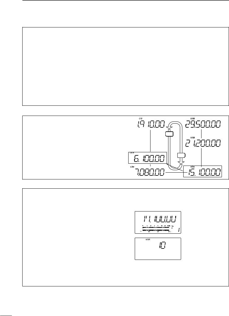
D Band stacking resister
The band stacking register automatically stores the last frequency and mode used for each band. This is convenient for contest operation, etc. The tables below shows the band stacking register default settings for each band.
BAND |
BAND |
BAND |
1.9 MHz |
1.91000 MHz |
CW |
|
|
|
3.5 MHz |
3.55000 MHz |
LSB |
|
|
|
7 MHz |
7.05000 MHz |
LSB |
|
|
|
10 MHz |
10.12000 MHz |
CW |
|
|
|
14 MHz |
14.10000 MHz |
USB |
|
|
|
General |
15.10000 MHz |
USB |
|
|
|
BAND |
BAND |
BAND |
18 MHz |
18.10000 MHz |
USB |
|
|
|
21 MHz |
21.20000 MHz |
USB |
|
|
|
24 MHz |
24.95000 MHz |
USB |
|
|
|
28 MHz |
28.50000 MHz |
USB |
|
|
|
29 MHz |
29.50000 MHz |
USB |
|
|
|
D Band selection
All HF ham bands and a general coverage receiver band are included in the IC-718.
Z DN
Push [∫ UP]/[√ DN] to select the desired band.
• Pushing [∫ UP]/[√ DN] continuously scrolls through the
available bands. General (new)
Note: For example, if 6.10000 MHz is resistered as the General coverage frequency, then the General coverage band automatically positions itself between 3.5 MHz and 7 MHz band.
UP Y
General (old)
D Programmable tuning steps
Programmable tuning steps are available to suit your operating requirements.
These tuning steps are:
• Selectable from 0.1, 1, 5, 9, 10, 100 kHz
q Push [TS], the programmable tuning step indicator, “ ,” then appears above the 1 kHz.
•Rotating the tuning dial changes the frequency according to the set tuning step.
w Push [TS] for 2 sec. while the programmable tuning step indicator appears to enter the tuning step set mode.
e Rotate the tuning dial to set the desired tuning step.
r Push [TS] to exit the tuning step set mode.
t Rotate the tuning dial to change the frequency according to the set tuning step.


 Programmable tuning


 step indicator
10 KHz tuning steps is selected.
18
 Loading...