


IC-40 JR

INSTRUCTION MANUAL
UHF C.R.S. FM TRANSCEIVER

FOREWORD
Thank you for purchasing the IC-40Jr UHF C.R.S. (Citizen
Radio Service) FM transceiver. This C.R.S. FM transceiver is
designed for those who require top quality, performance and
outstanding reliability under the most demanding conditions.
IMPORTANT
READ ALL INSTRUCTIONS carefully and completely
before using the transceiver.
SAVE THIS INSTRUCTION MANUAL– This instruc-
tion manual contains important operating instructions for
the IC-40Jr UHF C.R.S. FM transceiver.
CAUTION
R WARNING! NEVER hold the transceiver so that the an -
tenna is very close to, or touching exposed parts of the body,
especially the face or eyes, while transmitting. The transceiver
will perform best if the microphone is held 5 to 10 cm away from
your mouth and the transceiver is vertical.
R WARNING! NEVER operate the transceiver with a
headset or other audio accessories at high volume levels.
AVOID using or placing the transceiver in direct sunlight or in
areas with temperatures below 0˚C or above +55˚C
DO NOT push the PTTwhen not actually desiring to transmit.
i
DO NOT modify the transceiver for any reason.
DO NOT transmit for more than 3 sec., when operating with the
group mode and/or call ring function. Transmission in a form other
than speech is limited, and should be of a duration of less than
3 sec. as a compliance to ACA requirements in Australia.
The use of non-Icom battery packs/chargers may impair transceiver performance and invalidate the warranty.
This device complies with Standard Australia
Specification No. AS/NZS4365-1996.
SUPPLIED ACCESSORY
• Belt clip . . . . . . . . . . . . . . . . .1
ii

TABLE OF CONTENTS
FOREWORD . . . . . . . . . . . . . . . . . . . . . . . . . . . . . . . . . . . . . . . . . . . . i
IMPORTANT . . . . . . . . . . . . . . . . . . . . . . . . . . . . . . . . . . . . . . . . . . . . i
CAUTION . . . . . . . . . . . . . . . . . . . . . . . . . . . . . . . . . . . . . . . . . . . . . i–ii
SUPPLIED ACCESSORY . . . . . . . . . . . . . . . . . . . . . . . . . . . . . . . . . . ii
TABLE OF CONTENTS . . . . . . . . . . . . . . . . . . . . . . . . . . . . . . . . . . . iii
1 ACCESSORY . . . . . . . . . . . . . . . . . . . . . . . . . . . . . . . . . . . . . . . . . 1
2 PANELDESCRIPTION . . . . . . . . . . . . . . . . . . . . . . . . . . . . . . . . 2–4
‘ Switches, controls, keys and connectors . . . . . . . . . . . . . . . . 2–3
‘ Function display . . . . . . . . . . . . . . . . . . . . . . . . . . . . . . . . . . . . . 4
3 BATTERY PACK . . . . . . . . . . . . . . . . . . . . . . . . . . . . . . . . . . . . . 5–7
‘ Installing batteries in the battery case . . . . . . . . . . . . . . . . . . . . 5
‘ Battery pack charging . . . . . . . . . . . . . . . . . . . . . . . . . . . . . . . . . 6
‘ Battery pack life . . . . . . . . . . . . . . . . . . . . . . . . . . . . . . . . . . . . . 6
‘ Battery pack CAUTION . . . . . . . . . . . . . . . . . . . . . . . . . . . . . . . 6
‘ Charging connections . . . . . . . . . . . . . . . . . . . . . . . . . . . . . . . . . 7
4 BASIC OPERATION . . . . . . . . . . . . . . . . . . . . . . . . . . . . . . . . . . 8–9
‘ Power ON . . . . . . . . . . . . . . . . . . . . . . . . . . . . . . . . . . . . . . . . . . 8
‘ Adjusting the volume . . . . . . . . . . . . . . . . . . . . . . . . . . . . . . . . . 8
‘ Selecting the operating channel . . . . . . . . . . . . . . . . . . . . . . . . . 9
5 RECEIVE AND TRANSMIT . . . . . . . . . . . . . . . . . . . . . . . . . . . 10–11
6 REPEATER OPERATION . . . . . . . . . . . . . . . . . . . . . . . . . . . . . . . 12
7 SCAN FUNCTION . . . . . . . . . . . . . . . . . . . . . . . . . . . . . . . . . . . . . 13
8 GROUP MODE (CTCSS) . . . . . . . . . . . . . . . . . . . . . . . . . . . . 14–15
‘ Setting the group code . . . . . . . . . . . . . . . . . . . . . . . . . . . . . . . 14
9 RING FUNCTION . . . . . . . . . . . . . . . . . . . . . . . . . . . . . . . . . . . . . 16
‘ Smart-Ring . . . . . . . . . . . . . . . . . . . . . . . . . . . . . . . . . . . . . . . . 16
‘ Call-Ring . . . . . . . . . . . . . . . . . . . . . . . . . . . . . . . . . . . . . . . . . . 16
10 OTHER FUNCTIONS . . . . . . . . . . . . . . . . . . . . . . . . . . . . . . 17–22
‘ Initial set mode . . . . . . . . . . . . . . . . . . . . . . . . . . . . . . . . . . 17–19
‘ ATS (Automatic transponder system) . . . . . . . . . . . . . . . . . . . . 20
‘ Auto power save . . . . . . . . . . . . . . . . . . . . . . . . . . . . . . . . . . . . 20
‘ LCD backlight . . . . . . . . . . . . . . . . . . . . . . . . . . . . . . . . . . . . . . 20
‘ Low battery indicator . . . . . . . . . . . . . . . . . . . . . . . . . . . . . . . . 21
‘ Resetting the transceiver . . . . . . . . . . . . . . . . . . . . . . . . . . . . . 21
‘ Optional HM-75Afunctions . . . . . . . . . . . . . . . . . . . . . . . . . . . . 22
11 OPTIONS . . . . . . . . . . . . . . . . . . . . . . . . . . . . . . . . . . . . . . . . . . . 23
12 SPECIFICATIONS . . . . . . . . . . . . . . . . . . . . . . . . . . . . . . . . . 24–25
‘ Channel number and group number . . . . . . . . . . . . . . . . . . . . 25
13 WARRANTY . . . . . . . . . . . . . . . . . . . . . . . . . . . . . . . . . . . . . 26–27
iii
ACCESSORY
‘‘
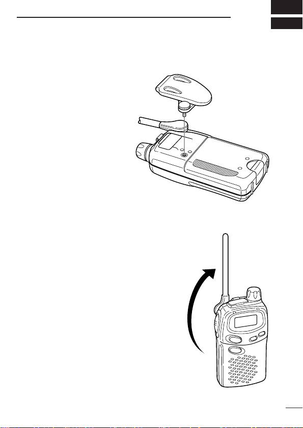
Accessory attachment
D Belt clip
Attach the belt clip using the
supplied screw.
D Antenna adjustment
Adjust the antenna position as shown in
the diagram.
Keep the jack cover attached when jacks
are not in use to protect from water, dust,
etc.
1
1
2
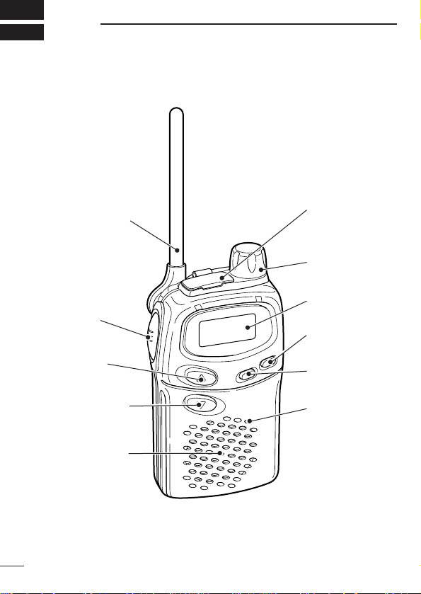
q ANTENNA
!1 SP/MIC
JACKS
!0 [VOL]
o FUNCTION
DISPLAY
i [POWER]
u [MODE]
y MIC
w [PTT]
e [UP/Y]
r [DOWN/Z]
t SPEAKER
‘‘
PANEL DESCRIPTION
Switches, controls, keys and
connectors
2

PANELDESCRIPTION
q ANTENNA
Extend the antenna completely when using the transceiver.
• The antenna collapses completely into the transceiver body for carrying purposes.
• The antenna can be adjusted 90 degrees from the regular position
when operating the transceiver in a horizontal position.
w PTT SWITCH [PTT]
• Push and hold to transmit; release to receive.
e CHANNEL UP SWITCH [UP/Y]
• Push to change the operating channel up.
• Push and hold to increment the operating channel continuously.
• While scanning, changes scanning direction. (p. 13)
r CHANNEL DOWN SWITCH [DOWN/Z]
• Push to change the operating channel down.
• Push and hold to decrement the operating channel continuously.
• While scanning, changes scanning direction. (p. 13)
t SPEAKER
y MICROPHONE [MIC]
u MODE SWITCH [MODE]
• Push to switch between Group mode and Normal mode. (p. 14)
• Push and hold for 1 sec. to open squelch; push and hold for 1 sec.
to close it again. (p. 8)
i POWER SWITCH [POWER]
• Push to turn the power ON; push for 1 sec. to turn the power OFF.
• Continue to hold [POWER] down for 2 sec. after power ON to turn
the lock function ON and OFF. (p. 18)
• Push to switch between repeater and simplex operation. (p. 12)
o FUNCTION DISPLAY (p. 4)
!0 VOLUME CONTROL [VOL]
Rotate clockwise to increase, and counterclockwise to decrease volume.
!11 EXTERNAL SPEAKER AND MICROPHONE JACKS
Connect an optional speaker-microphone or headset, if desired.
2
3

2
q
w
e
r
t
u
i
o!0 !1
y
PANELDESCRIPTION
‘‘
Function display
q TRANSMIT INDICATOR
Appears while transmitting.
w BUSY INDICATOR
Appears while receiving a signal or when the squelch is open.
e KEY LOCK INDICATOR (p. 18)
Appears during key lock function ON.
r REPEATER INDICATOR (p. 12)
Appears when repeater operation is selected.
t AUTO POWER OFF INDICATOR(p. 17)
Appears while the auto power off function is ON.
y LOW BATTERY INDICATOR (p. 21)
Appears or flashes when battery power has decreased to a specified level.
u PTT HOLD INDICATOR (p. 19)
• Appears when the “PTT hold” function is turned ON.
• Flashes while transmitting.
i ANSWER BACK INDICATOR (p. 20)
• Appears when you and your group are in the conversation area.
• Flashes when you or your group are out of the conversation area.
o POWER ON INDICATOR
Appears while the power is ON.
!0 CHANNEL NUMBER INDICATOR
Indicates operating channel number.
!1 GROUP NUMBER INDICATION (p. 14)
One of 01 to 38 appears while the Group function is turned ON.
4
BATTERY PACK
‘‘
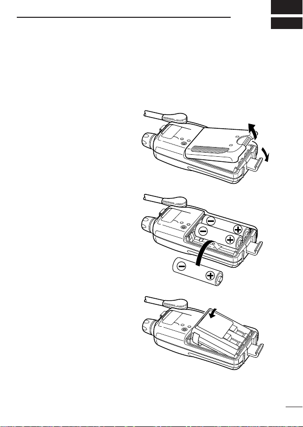
Installing batteries in the battery
3
case
Install 3 AA size alkaline, dry cell batteries or the optional BP-202
BATTERY PACK
q Remove the battery case
cover from the transceiver.
as illustrated below.
w Install 3
dry cells, or the BP-202.
• Be sure to observe the
NOTE: Keep battery contacts
clean. It’s a good idea to clean
battery terminals once a week.
×AA size alkaline,
correct polarity.
BP-202
5

BATTERYPACKS
3
‘‘
Battery pack charging
The optional BP-202
batteries and can be charged approx. 300 times. Charge the battery
pack before first operating the transceiver or when the battery pack
becomes exhausted.
If you want to be able to charge the battery pack more than 300
times, the following points should be observed:
1. Avoid overcharging. The charging period should be less than 48
hours.
2. Use the battery until it becomes almost completely exhausted
under normal conditions. We recommend battery charging just
after transmitting becomes impossible.
‘‘
Battery pack life
If your battery pack seems to have no capacity even after being
fully charged, completely discharge it by leaving the power ON all
day. Then, fully charge the battery pack again.
If the battery pack still does not retain a charge (or very little), a new
battery pack must be purchased.
‘‘
Battery pack CAUTION
NEVER short the terminals of the battery pack (or charging termi-
nals of the transceiver). Also, current may flow into nearby metal
objects, so be careful when placing battery packs (or the transceiver) in handbags, etc. Simply carrying with metal objects may
cause a short circuit. This will damage not only the battery pack but
also the transceiver.
BATTERY PACK
includes rechargeable Ni-Cd
6
 Loading...