


INSTRUCTION MANUAL
VHF FM TRANSCEIVER
iV8000
This device complies with Part 15 of the FCC rules. Operation is subject to the following two conditions: (1) This device may not cause harmful interference, and (2) this device must accept any interference received, including interference that may cause undesired operation.
FOREWORD
Thank you for purchasing this Icom product. The IC-V8000 VHF FM TRANSCEIVER is designed and built with Icom’s superior technology and craftsmanship. With proper care, this product should provide you with years of trouble-free operation.
We want to take a couple of moments of your time to thank you for making your IC-V8000 your radio of choice, and hope you agree with Icom’s philosophy of “technology first.” Many hours of research and development went into the design of your IC-V8000.
DFEATURES
75 W* of high transmit output power
(except Taiwan version)
Front mounted speaker for clear audio readability
Tone squelch, DTCS squelch standard
Dual color (amber & green) LCD backlight
Remote control microphone available
(optional for some versions)
Optional DTMF decoder
IMPORTANT
READ ALL INSTRUCTIONS carefully and completely before using the transceiver.
SAVE THIS INSTRUCTION MANUAL— This instruction manual contains important operating instructions for the IC-V8000.
EXPLICIT DEFINITIONS
WORD |
DEFINITION |
Personal injury, fire hazard or electric shock RWARNING! may occur.
CAUTION Equipment damage may occur.
NOTE
Recommended for optimum use. No risk of personal injury, fire or electric shock.
Icom, Icom Inc. and the 
 logo are registered trademarks of Icom Incorporated (Japan) in the United States, the United Kingdom, Germany, France, Spain, Russia and/or other countries.
i

CAUTIONS
RWARNING RF EXPOSURE! This device emits
Radio Frequency (RF) energy. Extreme caution should be observed when operating this device. If you have any questions regarding RF exposure and safety standards please refer to the Federal Communications Commission Office of Engineering and Technology’s report on Evaluating Compliance with FCC Guidelines for Human Radio frequency Electromagnetic Fields (OET Bulletin 65)
RWARNING! NEVER connect the transceiver to an AC outlet. This may pose a fire hazard or result in an electric shock.
RWARNING! NEVER operate the transceiver while driving a vehicle. Safe driving requires your full attention—anything less may result in an accident.
NEVER connect the transceiver to a power source of more than 16 V DC. This will ruin the transceiver.
NEVER connect the transceiver to a power source using reverse polarity. This will ruin the transceiver.
NEVER cut the DC power cable between the DC plug and fuse holder. If an incorrect connection is made after cutting, the transceiver may be damaged.
NEVER expose the transceiver to rain, snow or any liquids. The transceiver may be damaged.
NEVER operate or touch the transceiver with wet hands. This may result in an electric shock or ruin the transceiver.
NEVER place the transceiver where normal operation of the vehicle may be hindered or where it could cause bodily injury.
NEVER let objects impede the operation of the cooling fan on the rear panel.
DO NOT push the PTT when not actually desiring to transmit.
DO NOT allow children to play with any radio equipment containing a transmitter.
During mobile operation, DO NOT operate the transceiver without running the vehicle’s engine. When the transceiver’s power is ON and your vehicle’s engine is OFF, the vehicle’s battery will soon become exhausted.
BE CAREFUL! The transceiver will become hot when operating it continuously for long periods.
AVOID using or placing the transceiver in direct sunlight or in areas with temperatures below –10°C (+14˚F) or above +60°C (+140˚F).
AVOID the use of chemical agents such as benzine or alcohol when cleaning, as they can damage the transceiver’s surfaces.
USE Icom microphones only (supplied or optional). Other manufacturer’s microphones have different pin assignments and may damage the transceiver if attached.
ii
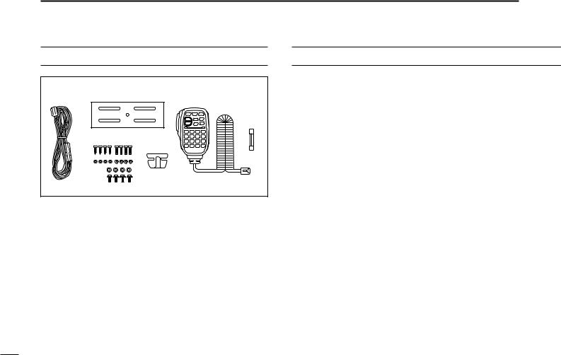
SUPPLIED ACCESSORIES
q |
w |
e |
r
t y
q DC power cable (3 m) . . . . . . . . . . . . . . . . . . . . . . . . . . . 1 w Mobile mounting bracket . . . . . . . . . . . . . . . . . . . . . . . . 1 e Microphone (HM-133V)* . . . . . . . . . . . . . . . . . . . . . . . . . 1 r Fuse (20 A) . . . . . . . . . . . . . . . . . . . . . . . . . . . . . . . . . . . 1 t Mounting screws, nuts and washers . . . . . . . . . . . . 1 set y Microphone hanger† . . . . . . . . . . . . . . . . . . . . . . . . . . . . 1
*HM-118N HAND MICROPHONE or HM-118TN/TAN DTMF MICROPHONE
supplied versions are also available.
†Depending on version.
TABLE OF CONTENTS |
|
|
FOREWORD ........................................................................................... |
i |
|
IMPORTANT ............................................................................................ |
i |
|
EXPLICIT DEFINITIONS ......................................................................... |
i |
|
CAUTIONS ............................................................................................. |
ii |
|
SUPPLIED ACCESSORIES .................................................................. |
iii |
|
TABLE OF CONTENTS ......................................................................... |
iii |
|
QUICK REFERENCE GUIDE ............................................................ |
I–VI |
|
|
■ Installation ....................................................................................... |
I |
|
■ Your first contact ........................................................................... |
IV |
|
■ Repeater operation ........................................................................ |
V |
|
■ Programming memory .................................................................. |
VI |
1 |
PANEL DESCRIPTION ................................................................. |
1–8 |
|
■ Front panel ..................................................................................... |
1 |
|
■ Function display ............................................................................. |
3 |
|
■ Rear panel ..................................................................................... |
5 |
|
■ Microphone (HM-133V) .................................................................. |
6 |
|
■ Microphone keypad ........................................................................ |
7 |
2 |
SETTING A FREQUENCY .......................................................... |
9–12 |
|
■ Preparation .................................................................................... |
9 |
|
■ Using the tuning dial ...................................................................... |
9 |
|
■ Using the keypad ......................................................................... |
10 |
|
■ Using the [Y]/[Z] keys ................................................................. |
10 |
|
■ Tuning step selection ................................................................... |
11 |
|
■ Lock functions .............................................................................. |
12 |
3 |
BASIC OPERATION ................................................................. |
13–16 |
|
■ Receiving ..................................................................................... |
13 |
|
■ Monitor function ........................................................................... |
13 |
|
■ Audio mute function ..................................................................... |
14 |
|
■ Squelch attenuator ....................................................................... |
14 |
|
■ Transmitting ................................................................................. |
15 |
|
■ Selecting output power ................................................................ |
15 |
|
■ One-touch PTT function ............................................................... |
16 |
iii

4 |
REPEATER OPERATION ......................................................... |
17–23 |
|
■ Accessing a repeater ................................................................... |
17 |
|
■ Subaudible tones ......................................................................... |
19 |
|
■ Offset frequency .......................................................................... |
21 |
|
■ Repeater lockout .......................................................................... |
21 |
|
■ Reverse duplex mode .................................................................. |
22 |
|
■ Auto repeater ............................................................................... |
23 |
5 |
MEMORY OPERATION ............................................................ |
24–34 |
|
■ General description ...................................................................... |
24 |
|
■ Memory channel selection ........................................................... |
24 |
|
■ Programming a memory channel ................................................. |
25 |
|
■ Transferring memory contents ..................................................... |
27 |
|
■ Memory clearing .......................................................................... |
29 |
|
■ Channel names programming ...................................................... |
30 |
|
■ Memory bank selection ................................................................ |
32 |
|
■ Memory bank setting .................................................................... |
33 |
|
■ Transferring bank contents .......................................................... |
34 |
6 |
CALL CHANNEL OPERATION ................................................ |
35–36 |
|
■ Call channel selection .................................................................. |
35 |
|
■ Call channel transferring .............................................................. |
35 |
|
■ Programming a call channel ........................................................ |
36 |
7 |
SCAN OPERATION .................................................................. |
37–42 |
|
■ Scan types ................................................................................... |
37 |
|
■ Scan start/stop ............................................................................. |
38 |
|
■ Scan edges programming ............................................................ |
39 |
|
■ Skip channel setting ..................................................................... |
41 |
|
■ Scan resume condition ................................................................ |
42 |
8 |
PRIORITY WATCH .................................................................... |
43–44 |
|
■ Priority watch types ...................................................................... |
43 |
|
■ Priority watch operation ............................................................... |
44 |
9 |
DTMF MEMORY ENCODER ..................................................... |
45–47 |
|
■ Programming a DTMF code ......................................................... |
45 |
■ Transmitting a DTMF code .......................................................... |
46 |
■ DTMF speed ................................................................................ |
47 |
10 POCKET BEEP AND TONE SQUELCH ................................... |
48–51 |
■ Pocket beep operation ................................................................. |
48 |
■ Tone/DTCS squelch operation ..................................................... |
50 |
■ Tone scan ..................................................................................... |
51 |
11 PAGER/CODE SQUELCH ........................................................ |
52–57 |
■ Pager function .............................................................................. |
52 |
■ Code programming ...................................................................... |
52 |
■ Pager operation ........................................................................... |
55 |
■ Code squelch ............................................................................... |
57 |
12 OTHER FUNCTIONS ................................................................ |
58–70 |
■ Set mode ...................................................................................... |
58 |
■ Initial set mode ............................................................................. |
62 |
■ Weather channel operation .......................................................... |
65 |
■ Microphone keys .......................................................................... |
67 |
■ Partial reset .................................................................................. |
68 |
■ All reset ........................................................................................ |
68 |
■ Data cloning ................................................................................. |
69 |
13 MAINTENANCE ........................................................................ |
71–73 |
■ Troubleshooting ........................................................................... |
71 |
■ Fuse replacement ........................................................................ |
72 |
■ Optional unit installation ............................................................... |
73 |
14 SPECIFICATIONS AND OPTIONS ................................................. |
74 |
15 MODE ARRANGEMENT ........................................................... |
75–76 |
1
2
3
4
5
6
7
8
9
10
11
12
13
14
15
iv
QUICK REFERENCE GUIDE
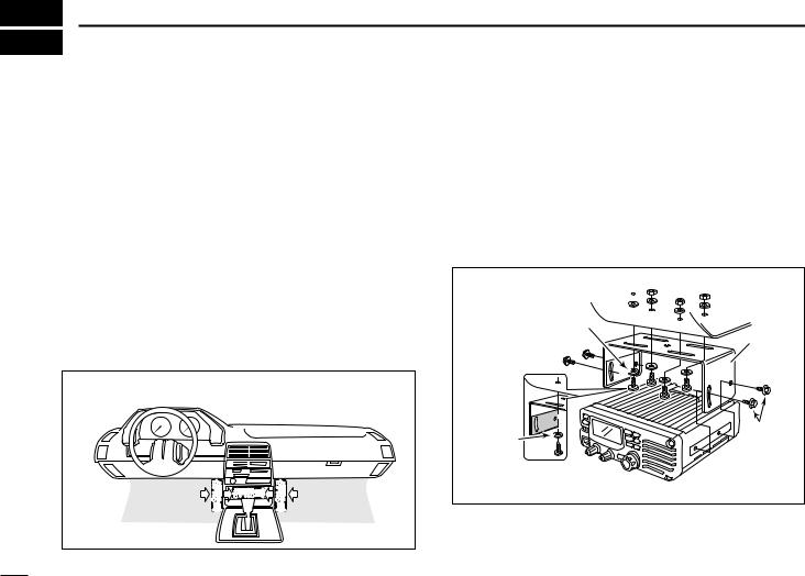
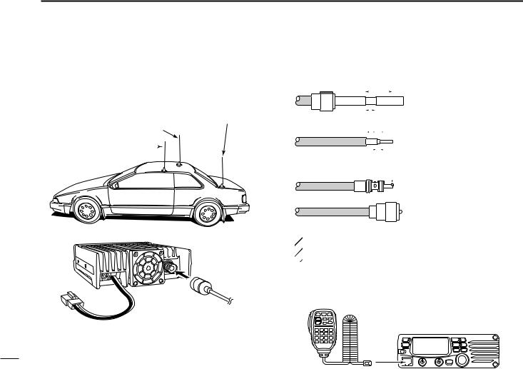
■ Installation
DLocation
Select a location which can support the weight of the transceiver and does not interfere with driving in any way. We recommend the locations shown in the diagram below.
NEVER place the transceiver where normal operation of the vehicle may be hindered or where it could cause bodily injury.
NEVER place the transceiver where air bag deployment may be obstructed.
DO NOT place the transceiver where hot or cold air blows directly onto it.
AVOID placing the transceiver in direct sunlight.
• Example— Installation location |
I
DUsing the mounting bracket
Drill 4 holes where the mounting bracket is to be installed.
•Approx. 5.5–6 mm (1⁄4″) when using nuts; approx. 2–3 mm (1⁄8″) when using self-tapping screws.
Insert the supplied screws, nuts and washers through the mounting bracket and tighten.
Adjust the angle for the clearest view of the function display.
Nut 
 Spring washer

Flat washer
Mounting bracket
When using self-tapping screws
Spring |
Mounting |
|
nut |
||
washer |
||
|
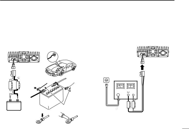
DBattery connection
NEVER connect the transceiver directly to a 24 V battery.
DO NOT use the cigarette lighter socket for power connections. (See p. 5 for details)
Attach a rubber grommet when passing the DC power cable through a metal plate to prevent short circuiting.
•CONNECTING TO A DC POWER SOURCE
• See p. 72 for fuse replacement.
|
|
Grommet |
|
IC-V8000 |
|
red |
− black |
+ red |
|
|
|
|
|
_ black |
|
Fuses |
|
|
20 A |
|
|
|
12 V |
12 V |
battery |
|
Supplied |
||
|
|
DC power cable |
NOTE: |
Crimp |
Solder |
Use terminals for the |
|
|
cable connections. |
|
|
QUICK REFERENCE GUIDE
DDC power supply connection
Use a 13.8 V DC power supply with at least 15 A capacity.
Make sure the ground terminal of the DC power supply is grounded.
•CONNECTING TO A DC POWER SUPPLY
• See p. 72 for fuse replacement.
|
|
IC-V8000 |
|
DC power |
|
|
supply 13.8 V |
|
to an |
|
|
AC |
− |
|
outlet |
|
|
|
|
Fuses |
|
− black |
20 A |
|
red |
|
II
QUICK REFERENCE GUIDE
DAntenna installation
• Antenna location
To obtain maximum performance from the transceiver, select a high-quality antenna and mount it in a good location. A nonradial antenna should be used when using a magnetic mount.
Trunk-mount Roof-mount antenna antenna (Drill a hole or use a magnetic mount.)
Gutter-mount antenna 
to antenna
III
• Antenna connector
The antenna uses a PL-259 connector.
• PL-259 CONNECTOR |
|
|
|
|||||||||
|
|
|
|
30 mm |
|
|
q Slide |
the coupling |
ring |
|||
|
|
|
|
|
||||||||
|
|
|
|
|
|
|
|
|
|
down. |
Strip the |
cable |
|
|
|
|
|
|
|
|
|
|
|||
|
|
|
|
|
|
|
|
|
|
|||
|
|
|
|
|
|
|
|
|
|
jacket and soft solder. |
||
|
|
|
|
|
|
|
|
|
|
|||
|
|
|
|
|
|
|
|
|
|
|||
Coupling ring |
10 mm (soft solder) |
||||||||
|
10 mm |
Soft |
|||||||
|
|
|
|
|
|
|
|||
|
|
|
|
|
|
|
solder |
||
|
|
|
|
|
|
|
|
|
|
|
|
|
|
|
|
|
|||
|
|
|
|
|
|
|
|
|
|
|
|
1–2 mm |
|||||||
|
|
solder solder |
|||||||
|
|
|
|
|
|
|
|
|
|
|
|
|
|
|
|
|
|
|
|
|
|
|
|
|
|
|
|
|
|
|
|
|
|
|
|
|
|
|
|
|
|
|
|
|
|
|
|
|
|
wStrip the cable as shown at left. Soft solder the center conductor.
eSlide the connector body on and solder it.
rScrew the coupling ring onto the connector body.
(10 mm ≈ 3⁄8 in)
 NOTE: There are many publications covering proper an-
  tennas and their installation. Check with your local dealer
  for more information and recommendations.
DConnecting a microphone
Connect a microphone to the eight-pin modular socket on the front panel of the transceiver.
*HM-133V; A different microphone may be supplied with some versions of the IC-V8000.
■ Your first contact
Now that you have your IC-V8000 installed in your car or shack, you are probably excited to get on the air. We would like to take you through a few basic operation steps to make your first “On The Air” an enjoyable experience.
1. Turning ON the transceiver
Before powering up your IC-V8000, you may want to make sure the audio volume and squelch level controls are set in 9–10 o’clock positions.
Set both [VOL] and [SQL] controls to 9–10 o’clock positions.
Although you have purchased a brand new transceiver, some settings may be changed from the factory defaults because of the QC process. Resetting the CPU is necessary to start from factory default.
[PWR] [SET(LOCK)] [MW(S.MW)]
While pushing [SET(LOCK)] and [MW(S.MW)], push [PWR] for 1 sec. to reset the CPU.
QUICK REFERENCE GUIDE
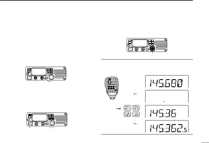
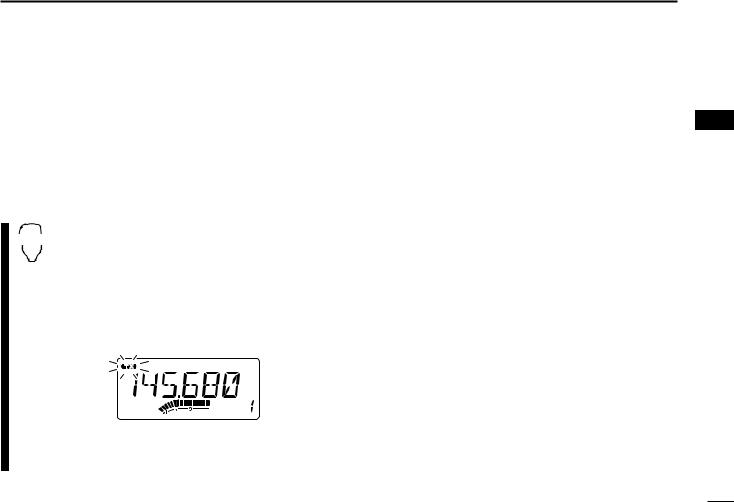
2. Tune the desired frequency
The tuning dial will allow you to dial in the frequency you want to operate. Pages 9 and 11 will instruct you on how to set the tuning speed.
Tuning dial
Using the HM-133V
You can directly enter the frequency with the HM-133V keypad.
[EXAMPLE]: Setting frequency to 145.3625 MHz. Push 
Push 
Push 
Push 
We hope these pointers have been helpful. Now you |
|
are ready to call CQ. |
IV |
|
QUICK REFERENCE GUIDE
■ Repeater operation
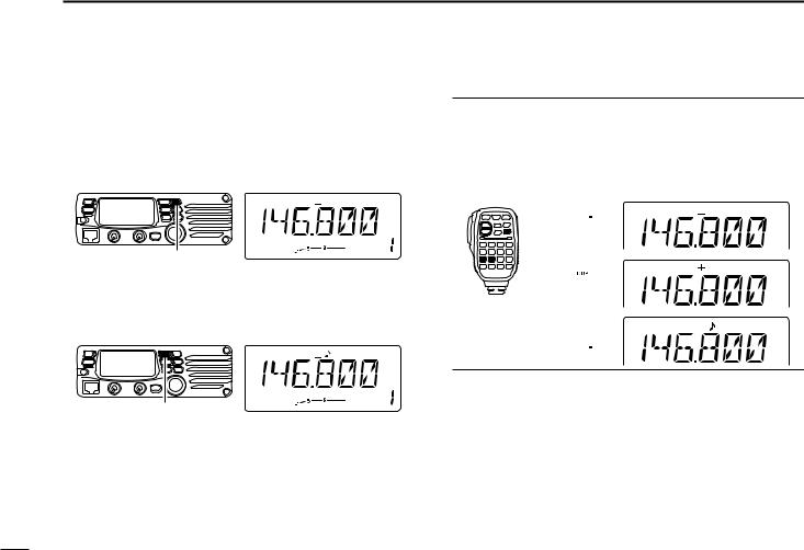
1. Setting duplex
Push [LOW(DUP)] for 1 sec. once or twice to select minus duplex or plus duplex.
•The USA and CSA versions have an auto repeater function, therefore, setting duplex is not required.
[LOW(DUP)]
2. Repeater tone
Push [TONE(T-SCAN)] several times until “ ” appears, if the repeater requires a subaudible to be accessed.
[TONE(T-SCAN)]
Using the HM-133V
Plus or minus duplex selection and the repeater tone setting can be made easily via HM-133V.
Push [DUP– 7(TONE)] for minus duplex; [DUP+ 8(TSQLS)] for plus duplex selection, push [FUNC] then [DUP– 7(TONE)] to turn the repeater tone ON.
Push 
Push 
Push  , then
V
■ Programming memory channels
The IC-V8000 has a total of 200 memory channels (including 6 scan edges and 1 call channel) for storing often used operating frequency, repeater settings, etc.
1. Setting a frequency
In VFO mode, set the desired operating frequency with repeater, tone and tuning steps, etc.
2. Selecting a memory channel
Momentarily push [MW(S.MW)], then rotate the tuning dial to select the desired memory channel.
• “M” indicator and memory channel number blink.
[MW(S.MW)]
3. Writing a memory channel
Push and hold [MW(S.MW)] for 1 sec. to program.
•3 beeps sound
•Memory channel number automatically increases when continuing to push [MW(S.MW)] after programming.
QUICK REFERENCE GUIDE
Using the HM-133V
qIn VFO mode, set the desired operating frequency, including offset direction, tone settings, etc.
wPush [FUNC] then [CLR A(MW)].
•“M” indicator and memory channel number blink.
Push  , then
e Push [Y]/[Z] to select the desired memory channel.
rPush [FUNC] then push [CLR A(MW)] for 1 sec. to program.
•3 beeps sound
•Memory channel number automatically increases when continuing to push [CLR A(MW)] after programming.
VI

 1 PANEL DESCRIPTION
■ Front panel
Function display (p. 3)
q |
PWR |
w |
M/CALL |
PRIO |
e
r t
q POWER SWITCH [PWR]
Turns power ON and OFF when pushed for 1 sec.
w MEMORY/CALL•PRIORITY SWITCH [M/CALL(PRIO)]
Push to select and toggle memory, call and weather channel* modes. (pgs. 24, 35, 65)
*Weather channels available for USA versions only.
Starts priority watch when pushed for 1 sec. (p. 44)
!3 |
!2 |
|
T-SCAN |
|
V/MHz |
|
SCAN |
|
SET |
!1 !0
DUP |
S.
BANK |
y u i o Speaker
e MICROPHONE CONNECTOR
Connects the supplied microphone.
r SQUELCH CONTROL [SQL]
Varies the squelch level. (p. 13)
•The RF attenuator activates and increases the attenuation when rotated clockwise to the center position and further.
t VOLUME CONTROL [VOL]
Adjusts the audio level. (p. 13)
1

y BANK•OPTION SWITCH [BANK(OPT)]
Push to select memory bank condition during memory mode. (p. 32)
Push for 1 sec. to select and toggle the pager and code squelch function when the optional UT-108 is installed. (p. 52)
u SET•LOCK SWITCH [SET(LOCK)]
Enters set mode when pushed. (p. 58)
Switches the lock function ON and OFF when pushed for 1 sec. (p. 12)
iTUNING DIAL [DIAL]
Selects the operating frequency (p. 9), memory channel (p. 24), the setting of the set mode item and the scanning direction (p. 38).
o MEMORY WRITE SWITCH [MW(S.MW)] (p. 25)
Selects a memory channel for programming.
Programs the selected memory channel when pushed for 1 sec.
•Continue to hold the switch to increment the memory channel automatically.
!0MONITOR•CHANNEL NAME SWITCH [MONI(ANM)]
Push to switch the monitor function ON and OFF. (p. 13)
In memory and call channel mode, switches the channel names or number ON and OFF. (p. 30)
PANEL DESCRIPTION |
1 |
!1OUTPUT POWER SWITCH [LOW(DUP)] |
1 |
Each push changes the output power selection. (p. 15)Select DUP–, DUP+ and simplex operation when
pushed for 1 sec. (p. 17)
!2TONE/TONE SCAN SWITCH [TONE(T-SCAN)]
Each push selects a tone function. (pgs. 17, 48)
•Tone encoder, pocket beep, tone squelch or tone function OFF can be selected.
Push for 1 sec. to start/stop the tone scan function. (p. 51)
!3VFO/MHz TUNING•SCAN SWITCH [V/MHz(SCAN)]
Selects and toggles VFO mode and 1 MHz (or 10 MHz for some versions) tuning when pushed. (p. 9)
Starts scan when pushed for 1 sec. (p. 38)
• Cancels a scan when pushed during scan.
DMicrophone connector (front panel view)
|
|
|
|
|
|
|
|
|
|
|
q +8 V DC output (Max. 10 mA) |
|
|
|
|
|
|
|
|
|
|
|
w Channel up/down |
|
|
|
|
|
|
|
|
|
|
|
e 8 V control IN |
|
|
|
|
|
|
|
|
|
|
|
r PTT |
|
q |
i |
|||||||||
|
t GND (microphone ground) |
||||||||||
|
|
|
|
|
|
|
|
|
|
|
|
|
|
|
|
|
|
|
|
|
|
|
y MIC (microphone input) |
|
|
|
|
|
|
|
|
|
|
|
u GND |
|
|
|
|
|
|
|
|
|
|
|
|
|
|
|
|
|
|
|
|
|
|
|
i Data IN |
|
|
|
|
|
|
|
|
|
|
|
|
2
1 PANEL DESCRIPTION
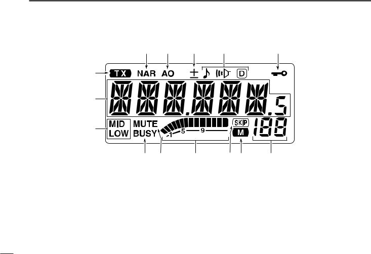
■ Function display
!5 |
!4 |
!3 |
!2 |
!1 |
q


 !0
!0
w
e
r t |
y |
qTRANSMIT INDICATOR
Appears while transmitting. (p. 15)
Flashes while transmitting with the one-touch PTT function. (p. 16)
wFREQUENCY READOUT
Shows the operating frequency, channel names, set mode contents, etc.
•Frequency decimal point flashes while scanning. (p. 38)
•“d” appears in place of the 1st digit while the DTMF memory function is in use. (p. 45)
u i o
eOUTPUT POWER INDICATORS
“LOW” appears when low output power; “LOW” and “MID” appear when low mid output power; “MID” appears when middle output power is selected
rBUSY INDICATOR (p. 13)
Appears when a signal is being received or the squelch is open.
Flashes while the monitor function is activated.
tAUDIO MUTE INDICATOR (p. 14)
Appears when the audio mute function is activated via microphone control.
3

yS/RF INDICATORS
Shows the relative signal strength while receiving signals. (p. 13)
Shows the output power level while transmitting. (p. 15)
uSKIP INDICATOR (p. 41)
Appears when the displayed memory channel is specified as a skip channel.
iMEMORY INDICATOR (p. 24)
Appears when memory mode is selected.
oMEMORY CHANNEL NUMBER INDICATORS
Shows the selected memory channel number. (p. 24)
“C” appears when the call channel is selected. (p. 35)
!0PRIORITY WATCH INDICATOR (p. 44)
Appears while the priority watch is activated; blinks while the watch is paused.
!1LOCK INDICATOR (p. 12)
Appears when the lock function is activated.
!2TONE INDICATORS
“ ” appears while the subaudible tone encoder is in use. (p. 17)
“ ” appears while the tone (CTCSS) squelch function is in use. (p. 48)
“ ” appears while the tone (DTCS) squelch function is in use. (p. 48)
“
 ” appears with the “
 ” or “
 ” indicator while the pocket beep function (CTCSS or DTCS) is in use. (p. 48)
PANEL DESCRIPTION |
1 |
!3DUPLEX INDICATORS (p. 17) |
1 |
“+” appears when plus duplex, “–” appears when minus duplex operation is selected.
!4AUTO POWER-OFF INDICATOR (p. 64)
Appears while the auto power-off function is in use.
!5NARROW MODE INDICATOR (p. 61) Appears when the narrow mode is selected.
Narrow mode is available with some USA versions only.
4
1 PANEL DESCRIPTION
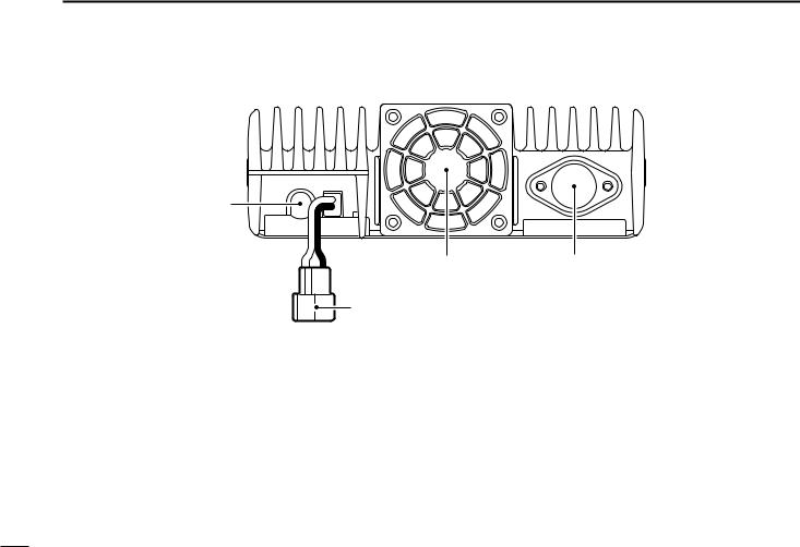
■ Rear panel
q
w
q SPEAKER JACK [SP]
Accepts an 8 Ω speaker.
• Audio output power is more than 2.0 W.
w POWER RECEPTACLE [DC13.8V]
Accepts 13.8 V DC ±15% with the supplied DC power cable.
NOTE: DO NOT use a cigarette lighter socket as a power source when operating in a vehicle. The plug may cause voltage drops and ignition noise may be superimposed onto transmit or receive audio.
e |
r |
e COOLING FAN
Rotates while transmitting.
Also rotates while receiving depending on the setting in set mode and transceiver’s temperature. (p. 61)
r ANTENNA CONNECTOR [ANT]
Connects a 50 Ω antenna with a PL-259 connector and a 50 Ω coaxial cable.
5
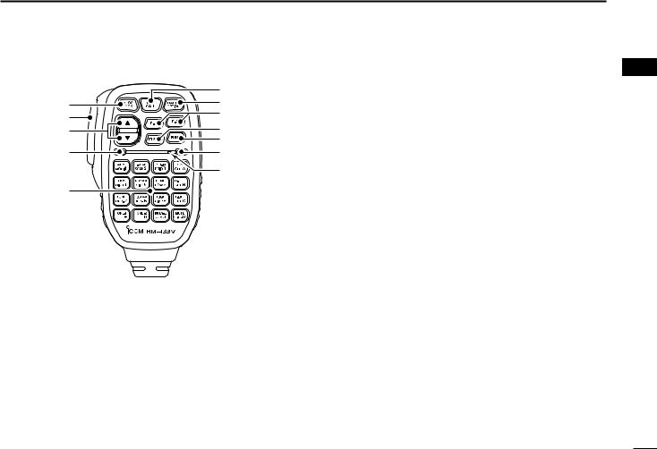
■ Microphone (HM-133V*)
|
!1 |
q |
!0 |
w |
o |
|
|
e |
i |
|
u |
r |
y |
|
Mic element |
t |
|
*A different microphone may be supplied depending on version.
qVFO/LOCK SWITCH [VFO/LOCK]
Push to select VFO mode. (p. 9)
Push for 1 sec. to switch the lock function ON and OFF. (p. 12)
wPTT SWITCH
Push and hold to transmit; release to receive.
Switches between transmitting and receiving while the one-touch PTT function is in use. (p. 16)
eUP/DOWN SWITCHES [Y]/[Z]
Push either switch to change operating frequency, memory channel, set mode setting, etc. (pgs. 10, 24)
Push either switch for 1 sec. to start scanning. (p. 38)
PANEL DESCRIPTION |
1 |
rACTIVITY INDICATOR |
1 |
Lights red while any key, except [FUNC] and [DTMF-S], is pushed, or while transmitting.
Lights green while the one-touch PTT function is in use. tKEYPAD (pgs. 7, 8)
yFUNCTION INDICATOR
Lights orange while [FUNC] is activated—indicates the secondary function of switches can be accessed.
Lights green when [DTMF-S] is activated—DTMF signals can be transmitted with the keypad.
uFUNCTION SWITCH [FUNC] (pgs. 7, 8)
iDTMF MEMORY SELECT SWITCH [DTMF-S] (p. 46)
oFUNCTION SWITCHES [F-1]/[F-2] (p. 67)
Program and re-call your desired transceiver conditions.
!0BANK/OPTION SWITCH [BANK/OPTION]
Push to selects memory bank condition during memory mode. (p. 32)
Push for 1 sec. to select and toggle pager and code squelch function when the optional UT-108 is installed. (p. 52)
!1MEMORY/CALL SWITCH [MR/CALL]
Push to select memory mode. (p. 24)
Push for 1 sec. to select call channel. (p. 35)
6

1 PANEL DESCRIPTION
■ Microphone keypad
KEY |
FUNCTION |
|
SECONDARY FUNCTION ( |
+key) |
OTHER FUNCTIONS |
|
|
|
|
|
|
||
|
Switches between opening and closing the |
In memory mode switches the channel names |
|
|
||
|
squelch. |
(p. 13) |
or number indication ON and OFF. |
(p. 31) |
|
|
|
|
|
|
|
|
|
|
Starts and stops scanning. |
(p. 38) |
Starts and stops tone scanning. |
(p. 51) |
|
|
|
|
|
|
|
|
|
|
Starts and stops priority watch. |
(p. 44) |
Turns the one-touch PTT function ON and |
|
|
|
|
|
|
OFF. |
(p. 16) |
|
|
|
|
|
|
|
|
|
|
Selects high output power. |
(p. 15) |
Turns the DTCS squelch ON. |
(p. 50) |
After pushing |
: |
|
|
|
|
|
Transmits the |
appropriate |
|
Selects mid. output power. |
(p. 15) |
Turns the DTCS pocket beep function ON. |
|||
|
DTMF code. |
(pgs. 20, 46) |
||||
|
|
|
|
(p. 49) |
When the DTMF memory en- |
|
|
Selects low output power |
(p. 15) |
Turns the DTMF memory encoder function |
coder is activated, push [0] to |
||
|
|
|
ON. |
(p. 45) |
[9] to transmit the appropriate |
|
|
|
|
|
|
DTMF memory contents . |
|
|
Selects minus duplex operation. |
(p. 18) |
Turns the subaudible tone encoder ON. |
|||
|
|
(p. 46) |
||||
|
|
|
|
(p. 18) |
|
|
|
|
|
|
|
|
|
|
|
|
|
|
|
|
|
Selects plus duplex operation. |
(p. 18) |
Turns the CTCSS pocket beep function |
|
|
|
|
|
|
ON. |
(p. 49) |
|
|
|
|
|
|
|
|
|
|
Selects simplex operation. |
(p. 18) |
Turns the tone squelch function ON. |
|
|
|
|
|
|
|
(p. 50) |
|
|
|
|
|
|
|
|
|
|
No primary function. |
|
Sends a 1750 Hz tone signal while pushing |
|
|
|
|
|
|
and holding. |
(p. 20) |
|
|
|
|
|
|
|
|
|
7

PANEL DESCRIPTION 1
1
KEY |
FUNCTION |
|
SECONDARY FUNCTION ( |
+key) |
OTHER FUNCTIONS |
|
|
|
|
|
|
|
|
|
Cancels frequency entry. |
(p. 10) |
Selects a memory channel for program- |
|
|
|
|
Cancels the scan or priority watch. |
ming. |
(p. 26) |
|
|
|
|
|
(pgs. 38, 44) |
Advances the memory channel number |
|
|
|
|
Exit set mode. |
(p. 58) |
when continuously pushed after pro- |
|
|
|
|
|
|
gramming is completed. |
(p. 26) |
|
|
|
|
|
|
|
|
|
|
Enters set mode |
(p. 58) |
DTMF memory OFF. |
(p. 46) |
|
|
|
Advances the set mode selection order |
|
|
|
|
|
|
after entering set mode. |
(p. 58) |
|
|
|
|
|
|
|
|
|
||
|
Sets the keypad for numeral input. |
Turns the subaudible tone encoder, pocket |
After pushing |
: |
||
|
|
(p. 10) |
beep or CTCSS/DTCS tone squelch OFF. |
Transmits the |
appropriate |
|
|
Reverses the set mode selection order |
(pgs. 18, 49, 50) |
||||
|
DTMF code. |
(pgs. 20, 46) |
||||
|
after entering set mode. |
(p. 58) |
|
|
|
|
|
|
|
|
|
|
|
|
Adjusts the squelch level increments. |
Mutes the audio. |
(p. 14) |
|
|
|
|
|
(p. 13) |
• Mute function is released when any oper- |
|
|
|
|
|
|
ation is performed. |
|
|
|
|
|
|
|
|
|
|
|
No primary function. |
|
Sends a 1750 Hz tone signal for 0.5 sec. |
|
|
|
|
|
|
|
(p. 20) |
|
|
|
|
|
|
|
||
|
Adjusts the squelch level decrement. |
Locks the digit keys on the keypad (includ- |
|
|
||
|
|
(p. 13) |
ing the A to D, # and M keys. |
(p. 12) |
|
|
|
|
|
|
|
|
|
8
 2 SETTING A FREQUENCY
■ Preparation
DTurning power ON/OFF
Push [PWR] for 1 sec. to turn power ON and OFF.
Push [PWR] for 1sec.
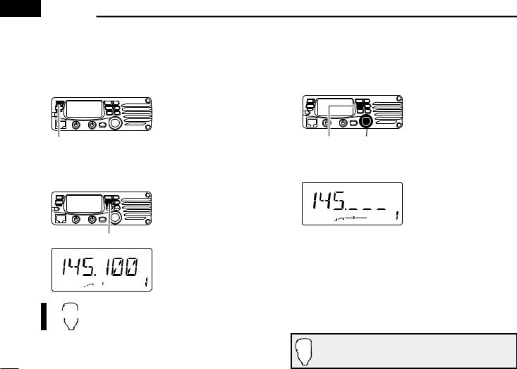
DVFO mode selection
The transceiver has 2 basic operating modes: VFO mode and memory mode.
Push [V/MHz(SCAN)] to select VFO mode.
Push [V/MHz(SCAN)]
Push [VFO/LOCK] to select VFO mode.
VFO/LOCK
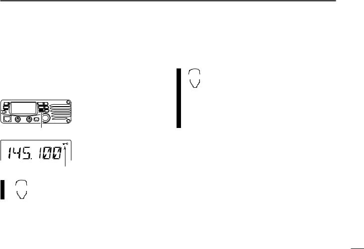
■ Using the tuning dial
qRotate the tuning dial to set the frequency.
•If VFO mode is not selected,
push [V/MHz(SCAN)] to select VFO mode.
• The frequency changes ac-
[V/MHz(SCAN)] Tunig dial
cording to the selected tuning steps. (p. 11)
wTo change the frequency in 1 MHz (10 MHz for some versions) steps, push [V/MHz(SCAN)], then rotate the tuning dial.
• Pushing [V/MHz(SCAN)] for 1 sec. starts scan function. If scan starts, push [V/MHz(SCAN)] again to cancel it.
The display shows that the
1 MHz tuning step is selected.
Note that in this manual, sections beginning with a microphone icon (as above), designate operation via the HM133V microphone.
9
■ Using the keypad
The frequency can be directly set via numeral keys on the microphone.
z Push [VFO/LOCK] to VFO mode, if necessary.
ENT x Push [ENT C(T-OFF)] to activate the keypad for
C |
digit input. |
|
cPush 6 keys to input a frequency.
•When a digit is mistakenly input, push [ENT C(T-OFF)] to clear the input, then repeat input from the 1st digit.
•Pushing [CLR A(MW)] clears input digits and retrieves the frequency.
[EXAMPLE]: Setting frequency to 145.3625 MHz.
Push 
Push 
Push 


Push 
SETTING A FREQUENCY 2
■ Using the [Y]/[Z] keys
Push [Y] or [Z] to select the desired frequency. 2
YZ • Pushing [Y]/[Z] for 1 sec. activates a scan. If scan starts, push [Y]/[Z] again or push [CLR A(MW)] to cancel it.
10
2 SETTING A FREQUENCY
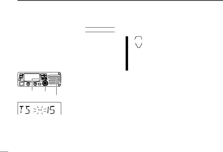
■ Tuning step selection
USING SET MODE
Tuning steps are the minimum frequency change increments when you rotate the tuning dial or push [Y]/[Z] on the microphone. The following tuning steps are available.
• 5 kHz |
• 10 kHz |
• 12.5 kHz |
• 15 kHz |
• 20 kHz |
• 25 kHz |
• 30 kHz |
• 50 kHz |
NOTE: For convenience, select a tuning step that matches the frequency intervals of repeaters in your area.
[SET(LOCK)] Tuning dial |
[MW(S.MW)] |
15 kHz tuning step
qPush [V/MHz(SCAN)] to select VFO mode, if necessary.
wPush [SET(LOCK)] to enter set mode.
ePush [SET(LOCK)] or [MW(S.MW)] several times until “TS” appears as shown at left.
rRotate the tuning dial to select the desired tuning step.
tPush [TONE(T-SCAN)] to exit set mode.
VFO/LOCK |
z Push [VFO/LOCK] to select VFO mode, if |
necessary. |
|
|
x Push [SET B(D-OFF)] to enter set mode. |
|
c Push [SET B(D-OFF)] or [ENT C(T-OFF)] |
|
several times until “TS” appears. |
vPush [Y] or [Z] to select the desired tuning step.
b Push [CLR A(MW)] to exit set mode.
11
■ Lock functions
To prevent accidental channel changes and unnecessary function access, use the lock function. The transceiver has 2 different lock functions.
DFrequency lock
This function locks the tuning dial and switches electronically and can be used together with the microphone lock function.
Push [SET(LOCK)] for 1 sec.
Appears
Push [SET(LOCK)] for 1 sec. to turn the lock function ON and OFF.
•[PTT], [MONI(ANM)], [VOL] and [SQL] can be used while the channel lock function is in use. Also, TONE-1, TONE-2, DTMF tones or DTMF memory contents can be transmitted from the microphone.
Push [VFO/LOCK] for 1 sec. to switch the
VFO/LOCK |
lock function ON and OFF. |
SETTING A FREQUENCY 2
DMicrophone keypad lock |
2 |
This function locks the microphone keypad.
Push [FUNC] then [SQLZ D(16KEY-L)] to 16KEY-L switch the microphone keypad lock function
ON and OFF.
•[PTT], [VFO/LOCK], [MR/CALL], [BANK/OPTION],
[Y], [Z], [F-1], [F-2], [DTMF-S] and [FUNC] on the microphone can be used.
•All switches on the transceiver can be used.
•The keypad lock function is released when the power is turned OFF then ON again.
12
 3 BASIC OPERATION
■ Receiving
q Push [PWR] for 1 sec. to turn power ON.
wSet the audio level.
Push [MONI(ANM)] to open the squelch.
Rotate the [VOL] control to adjust the audio output level.
Push [MONI(ANM)] again to close the squelch.
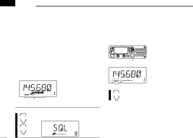
eSet the squelch level.
Rotate [SQL] fully counterclockwise in advance.
Rotate [SQL] clockwise until the noise just disappears.
When interference is received, rotate [SQL] clockwise again for attenuator operation.
r Set the operating frequency. (pgs. 9, 10)
tWhen receiving a signal on the set frequency, squelch opens and the transceiver emits audio.
• “BUSY” appears and the S/RF indicator shows the relative signal strength for the received signal.
Appears when receiving a signal.
CONVENIENT!
The squelch level can also be adjusted with
SQLY [SQLY D(MUTE)] and [SQLZ #(16KEY-L)].
D
SQLZ
#
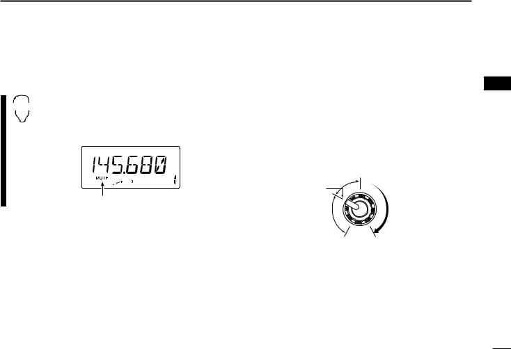
■ Monitor function
This function is used to listen to weak signals without disturbing the squelch setting or to open the squelch manually even when mute functions such as the tone squelch are in use.
Push [MONI(ANM)] to open the squelch.
• “BUSY” blinks.
• Push [MONI(ANM)] again to
cancel the function.
Push [MONI(ANM)]
Push [MONI 1(ANM)] to open the squelch.
MONI • Push [MONI 1(ANM)] again to cancel the function. 1
13
■ Audio mute function
This function temporarily mutes the audio without disturbing the volume setting.
Push [FUNC] then [SQLY D(MUTE)] to mute
MUTE |
audio signals. |
•“MUTE” appears.
•Push [CLR A(MW)] (or any other key) to cancel the function.
Appears
BASIC OPERATION 3
■ Squelch attenuator
The transceiver has an RF attenuator related to the squelch
level setting. Approx. 10 dB attenuation is obtained at maxi- 3 mum setting.
Rotate [SQL] clockwise past the 12 o’clock position to activate the squelch attenuator.
•Attenuation level can be adjusted up to 10 dB (approx.) between 12 o’clock and fully clockwise position.
•When setting the squelch from the microphone, a level greater than ‘19’ activates the squelch attenuator.
Noise squelch
Squelch  threshold
Squelch is |
Squelch |
|
attenuator |
||
open. |
||
|
||
Shallow |
Deep |
14
3 BASIC OPERATION
■ Transmitting
CAUTION: Transmitting without an antenna will damage the transceiver.
NOTE: To prevent interference, listen on the channel before transmitting by pushing [MONI(ANM)], or [MONI 1(ANM)] on the microphone.
qSet the operating frequency. (pgs. 9, 10)
•Select output power if desired. See section at right for details. w Push and hold [PTT] to transmit.
•“$” appears.
•The S/RF indicator shows the output power selection.
•A one-touch PTT function is available. See p. 16 for details.
e Speak into the microphone using your normal voice level.
•DO NOT hold the microphone too close to your mouth or speak too loudly. This may distort the signal.
r Release [PTT] to return to receive.
IMPORTANT! (for 75 W transmission):
The IC-V8000 is equipped with protection circuit to protect the power amplifier circuit from high SWR (Standing Wave Ratio) and temperature. When a high SWR antenna or no antenna is connected, or when the transceiver temperature becomes extremely high, the transceiver reduces transmit output power to 25 W (approx.) automatically.
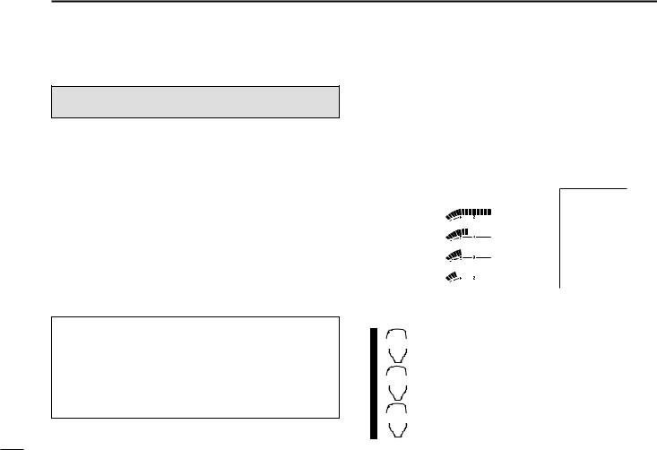
■ Selecting output power
The transceiver has 4* output power levels to suit your operating requirements. Low output powers during short-distance communications may reduce the possibility of interference to other stations and will reduce current consumption.
*The Taiwan version has only 3 levels.
Push [LOW(DUP)] several times to select the output power.
|
S/RF INDICATOR |
POWER OUTPUT |
|
|
|
|
|
Taiwan |
|
|
|
|
|
|
|
|
|
|
|
|
|
|
|
|
High: |
75 W |
24 W |
|
|
|
|
|
|
|
|
|
Mid.: |
25 W* |
10 W* |
|
|
|
|
|
|
|
|
|
Mid. Low: |
10 W* |
N/A |
|
|
|
|
|
|
|
|
|
Low: |
5 W* |
5 W* |
|
|
|
|
|
|
|
|
• The output power can be changed while transmitting. |
*approx. |
||||
The microphone can also be used to select output power.
Push [HIGH 4(DTCS)] for high output power; HIGH [MID 5(DTCSS)] for middle output power; and
4[LOW 6(DTMF)] for low output power.
• The output power can be changed via the microphone
MID |
during receive only. |
5 |
|
LOW 6
15
■ One-touch PTT function
The PTT switch can be operated as a one-touch PTT switch (each push switches between transmit/receive). Using this function you can transmit without pushing and holding the PTT switch.
To prevent accidental, continuous transmissions with this function, the transceiver has a time-out timer. See p. 63 for details.
z Push [FUNC] then [PRIO 3(PTT-M)] to turn the PTT-M one-touch PTT function ON.
•The activity indicator lights green.
x Push [PTT] to transmit and push again to receive.
•Two beeps sound when transmission is started and a long beep sounds when returning to receive.
•“$” flashes when transmitting with the one-touch PTT function.
cPush [FUNC] then [PRIO 3(PTT-M)] to turn the one-touch PTT function OFF.
• The activity indicator goes out.
BASIC OPERATION 3
3
16
 Loading...