


INSTRUCTION MANUAL
COMMUNICATIONS RECEIVER
iR3
This device complies with Part 15 of the FCC rules. Operation is subject to the following two conditions: (1) This device may not cause harmful interference, and (2) this device must accept any interference received, including interference that may cause undesired operation.

FOREWORD |
|
CAUTIONS |
|
||
READ ALL INSTRUCTIONS carefully and completely |
RWARNING! NEVER operate the receiver with a head- |
||||
before using the receiver. |
set or other audio accessories at high volume levels. Hearing |
||||
SAVE THIS INSTRUCTION MANUAL — This in- |
experts advise against continuous high volume operation. If |
||||
you experience a ringing in your ears, reduce the volume level |
|||||
struction manual contains important operating instructions for |
or discontinue use. |
||||
the IC-R3. |
|
|
AVOID using or placing the receiver in direct sunlight or in |
||
|
|
|
|||
|
|
|
areas with temperatures below –10°C (+14°F) or above |
||
EXPLICIT DEFINITIONS |
+60°C (+140°F). |
||||
Even when the receiver power is OFF, a slight current still |
|||||
|
|
|
|||
The explicit definitions below apply to this instruction manual. |
flows in the circuits. Remove batteries from the receiver when |
||||
not using it for a long time, otherwise, the installed batteries |
|||||
|
|
|
|||
WORD |
DEFINITION |
|
will become exhausted. |
||
RWARNING |
Personal injury, fire hazard or electric |
|
REMOVE any cables from the [DC 6V] jack after operation or |
||
shock may occur. |
|
||||
|
|
charging a battery pack. |
|||
CAUTION |
Equipment damage may occur. |
|
|||
|
LCDs are produced using high-density manufacturing tech- |
||||
NOTE |
If disregarded, inconvenience only. No risk |
|
|||
|
nology resulting in 99.98% active dots, however, up to 0.02% |
||||
of personal injury, fire or electric shock. |
|
||||
|
|
of the dots may be non-active and/or continuously active. This |
|||
|
|
|
|||
|
|
|
is normal and does not indicate LCD malfunction. |
||
|
|
|
For U.S.A. only |
||
Versions of the IC-R3 which display the “CE” symbol on the serial |
CAUTION: Changes or modifications to this device, not ex- |
||||
number seal, comply with the essential requirements of the Euro- |
pressly approved by Icom Inc., could void your authority to |
||||
pean Radio and Telecommunication Terminal Directive 1999/5/EC. |
operate this device under FCC regulations. |
||||
i
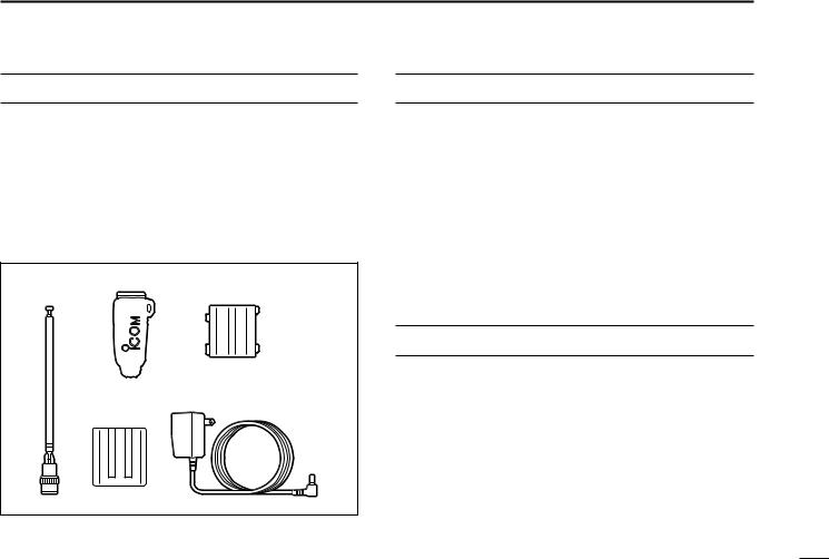
SUPPLIED ACCESSORIES
Accessories included with the receiver: |
Qty. |
||
q Antenna (FA-B03RE) ...................................................... |
|
1 |
|
w Belt clip |
........................................................................... |
|
1 |
e Battery spacer ................................................................ |
|
1 |
|
r Battery pack* ..................................................(BP-206) |
|
1 |
|
t Wall charger* ............................................(BC-136A/D) |
|
1 |
|
* Not supplied with some versions. |
|
|
|
q |
w |
e |
|
rt
OPERATING THEORY
Electromagnetic radiation which has frequencies of 20,000 Hz (20 kHz*) and above is called radio frequency (RF) energy because it is useful in radio transmissions. The IC-R3 receives RF energy from 0.495 MHz* to 2450.00 MHz and converts it into audio frequency (AF) energy which in turn actuates a loudspeaker to create sound waves. AF energy is in the range of 20 to 20,000 Hz.
*kHz is an abbreviation of kilohertz or 1000 hertz, MHz is abbreviation of megahertz or 1,000,000 hertz, where hertz is a unit of frequency.
OPERATING NOTES
The IC-R3 may receive its own oscillated frequency, resulting in no reception or only noise reception, on some frequencies.
The IC-R3 may receive interference from extremely strong signals on different frequencies or when using an external high-gain antenna.
ii

TABLE OF CONTENTS
1 |
ACCESSORY ATTACHMENT ............ |
1 |
2 |
PANEL DESCRIPTION .................. |
2 – 6 |
|
■Panel description ............................. |
2 |
|
■Function display ............................... |
4 |
|
■Dual LCD ......................................... |
6 |
3 |
FREQUENCY AND CHANNEL |
|
|
SETTING ....................................... |
7 – 9 |
|
■VFO and memory channels ............. |
7 |
|
■Operating band selection ................. |
7 |
|
■Setting a frequency .......................... |
8 |
|
■Setting a tuning step ........................ |
8 |
|
■Selecting a memory channel ........... |
9 |
|
■Lock function .................................... |
9 |
|
■Attenuator function ........................... |
9 |
4 |
BASIC OPERATION .................. |
10 – 13 |
|
■Receiving ....................................... |
10 |
|
■Setting volume level ....................... |
11 |
|
■Setting squelch level ...................... |
11 |
|
■Monitor function ............................. |
12 |
|
■Receive mode selection ................. |
12 |
|
■Display backlighting ....................... |
13 |
5 |
MEMORY CHANNELS ............... |
14 – 17 |
|
■General .......................................... |
14 |
|
■Programming during selection ....... |
14 |
|
■Programming after selection .......... |
15 |
|
■Transferring memory contents to |
|
|
another memory ............................ |
15 |
|
■Memory bank selection .................. |
16 |
|
■Memory clear ................................. |
16 |
|
■Memory names .............................. |
17 |
6 |
SCAN OPERATION ................... |
18 – 24 |
|
■Scan types ..................................... |
18 |
|
■Full/band/programmed scan .......... |
19 |
|
■Memory (bank) scan ...................... |
20 |
|
■Selecting scan edges ..................... |
21 |
|
■Skip channel setting ....................... |
22 |
|
■Scan resume condition .................. |
22 |
|
■Frequency skip function ................. |
24 |
7 |
PRIORITY WATCH .................... |
25 – 27 |
|
■Priority watch types ....................... |
25 |
|
■Priority watch operation ................. |
26 |
8 |
SUBAUDIBLE TONE |
|
|
OPERATION .............................. |
28 – 30 |
|
■Tone squelch operation .................. |
28 |
|
■Pocket beep operation ................... |
29 |
|
■Tone scan ...................................... |
30 |
9 |
DUPLEX OPERATION .............. |
31 – 32 |
10 |
BAND SCOPE .................................. |
33 |
11 |
TV OPERATION ........................ |
34 – 36 |
|
■TV operation .................................. |
34 |
|
■ATV operation ................................ |
36 |
12 |
DIRECTION FINDING ...................... |
37 |
13 |
OTHER FUNCTIONS ................. |
38 – 45 |
|
■Set mode ....................................... |
38 |
|
■Dial select step .............................. |
39 |
|
■Beep tones ..................................... |
40 |
|
■Auto power-off function .................. |
40 |
|
■Power saver ................................... |
41 |
|
■Monitor switch action ..................... |
41 |
|
■Dial speed acceleration ................. |
42 |
|
■Lock function effect ........................ |
42 |
|
■Display mode selection .................. |
43 |
|
■Display contrast ............................. |
43 |
|
■Display brightness ......................... |
44 |
|
■Display background color ............... |
44 |
|
■Cloning function ............................. |
45 |
|
■Partial reset .................................... |
45 |
|
■Total reset ...................................... |
45 |
14 |
BATTERY CHARGING .............. |
46 – 47 |
|
■Battery cautions ............................. |
46 |
|
■Battery charging ............................ |
46 |
15 |
OPERATION FLOW CHART....... |
48 – 49 |
16 |
TV FREQUENCY TABLE ........... |
50 – 53 |
17 |
SPECIFICATIONS AND |
|
|
OPTIONS ................................... |
54 – 55 |
18 |
TROUBLESHOOTING ...................... |
56 |
19 |
QUICK REFERENCE ................. |
57 – 58 |
iii

◊Antenna
Insert the supplied antenna into the antenna connector and screw down the antenna as shown at right.
Keep the jack cover attached when jack is not in use to avoid bad contacts from dust and moisture.
Commercially available antennas (BNC) may increase receiver performance.
ACCESSORY ATTACHMENT 1 
Keep battery contacts clean. It’s a good idea to clean battery terminals once a week.
◊Belt clip
Conveniently attaches to your belt.
Slide the belt clip into the plastic loop on the back of the receiver.
◊Battery installation
qRemove the battery cover from the receiver.
wFor alkaline battery use, attach the supplied battery spacer.
eInstall 3 R6 (AA) size alkaline batteries or Li-Ion battery pack (BP-206; p. 46).
•Be sure to observe the correct polarity.
•Charge Li-Ion battery pack before use.
◊Handstrap (not supplied from Icom)
Slide a commercially available handstrap through the loop on the side of the receiver or belt clip as illustrated below. Facilitates carrying.
w
q e
e
1
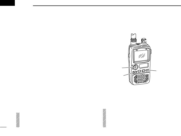
 2 PANEL DESCRIPTION
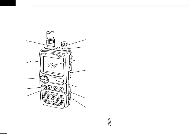
■ Panel description
q |
!1 |
|
|
|
!0 |
|
Color LCD |
w |
(p. 6) |
|
|
|
o |
e |
r |
 i
i
Sub LCD (p. 4)
t |
u |
|
|
|
y |
|
SPEAKER |
q ANTENNA CONNECTOR (p. 1)
Connects the supplied antenna.
2
w FUNCTION SWITCH [FUNC]
While pushing this switch, other switches and tuning dial perform secondary functions.
•“Push [FUNC] + a switch” means “while pushing the [FUNC] switch, push the switch” as indicated by the mark e.g. [↕] etc.
e MULTI FUNCTION SWITCH [MULTI]
Push [↕] to adjust the audio level. (p. 11)
Push [FUNC] + [↕] to toggle between AM TV (frequency selection), amateur TV (ATV-type) and WFM/FM/AM modes when the color LCD is OFF. (p. 34)
Push [FUNC] + [↕] for 2 sec. to toggle the color LCD ON and OFF (p. 6, 30 MHz and above only).
Push [FUNC] + [↕] to select color LCD function when the color LCD is ON. (p. 6)
Push [↔] to select the operating band (VHF, UHF, etc.) in VFO mode. (p. 7)
•Broadcast, HF, 50 MHz, FM broadcast, VHF avionics, 144 MHz, 300 MHz, 400 MHz, 800 MHz, 1200 MHz, 2400 MHz and TV bands (channel selection) can be selected.
Push [FUNC] + [↔] to select the dial select step. (p. 39)
Push [↔] for 2 sec. to start a scan. (pgs. 19, 20)
Push [FUNC] + [↔] for 2 sec. to start a tone scan. (p. 30)
Push [↕] means push ó up or down; and push [↔] means push ó left or right.
r POWER SWITCH [POWER]
Push for 2 sec. to toggle the receiver power ON and OFF.

t VFO/MEMORY SWITCH [V/M (SKIP)]
Push [V/M] to toggle between VFO and memory modes. (p. 7)
Push [V/M] for 1 sec. to enter memory write mode.
Push [V/M] for 2 sec. to write the operating frequency into the selected memory channel in VFO mode. Keep pushing for 2 sec. or more to automatically select the next memory channel, if desired. (p. 14)
Push [FUNC] + [(V/M)SKIP] to toggle the frequency skip function ON or OFF in VFO mode. (p. 24)
Push [FUNC] + [(V/M) SKIP] to toggle the channel as skip, program skip or non-skip channel in memory mode. (p. 22)
Push [FUNC] + [(V/M) SKIP] for 2 sec. to program the memory name while displaying the memory channel in the color LCD. (p. 17)
y MODE SWITCH [MODE (SET)]
Push [MODE] to select the receive mode. (p. 12)
Push and hold [MODE] to enter tuning step setting condition and rotate the tuning dial to select the tuning step. (p. 8)
Push [FUNC] + [(MODE)SET] to enter set mode. (p. 38)
Push [FUNC] + [(MODE) SET] for 2 sec. to toggle the lock function ON and OFF. (pgs. 9, 24)
u MONITOR SWITCH [SQL (ATT)]
Push and hold to temporarily open the squelch and monitor the operating frequency. (pgs. 12, 41)
PANEL DESCRIPTION 2
While pushing [SQL], rotate the tuning dial to set the squelch threshold level. (p. 11)
Push [FUNC] + [(SQL) ATT] to enter the attenuator setting condition and rotate the tuning dial to set the attenuation level. (p. 9)
iEXTERNAL DC POWER JACK [DC 6V]
Allows charging of the BP-206 using the BC-136A/D wall charger, or using an optional CP-18A/E cigarette lighter cable.
o AUDIO AND VIDEO OUTPUT JACK [A/V OUT]
Outputs a composite video and audio signals. (p. 5)
!0TUNING DIAL [DIAL]
Rotate [DIAL] to set operating frequencies, memory channels, set mode contents, etc. (pgs. 7, 38)
While scanning, changes the scanning direction. (p. 19)
While pushing [SQL], sets the squelch level. (p. 11)
While pushing [FUNC], sets the operating frequency in 100 kHz, 1 MHz or 10 MHz steps in VFO mode. (pgs. 8, 39)
While pushing [FUNC], sets the memory bank in memory mode. (p. 16)
While pushing [↔], selects programmed scan bank or memory bank in VFO or memory mode, respectively. Release [↔] to start the scan. (pgs. 19, 20)
!1EXTERNAL SPEAKER JACK [SP]
Connects an optional earphone or headphone. The internal speaker will not function when any external equipment
is connected. (See p. 55 for a list of available options.)
3
2 PANEL DESCRIPTION
■ Function display
|
|
q w e |
r |
|
|
|||||||||||||
|
|
|
|
|
|
|
|
|
|
|
|
|
|
|
|
|
|
|
|
|
AM WFM |
|
|
|
DUP |
|
|
|
TSQL |
|
PRIO |
|
|
||||
|
|
|
|
|
|
|
|
|
|
|
|
|
|
|
75 |
t |
||
|
|
|
|
|
|
|
|
|
|
|
|
|
|
|
50 |
|||
|
|
|
|
|
|
|
|
|
|
|
|
|
|
|
|
|
||
!2 |
|
|
|
|
|
|
|
|
|
|
|
|
|
|
25 |
|
|
|
!1 |
RX ATT |
|
y |
|||||
|
|
|
|
|
|
|
|
|
|
|
|
|
|
|
|
|
|
|
|
|
|
|
|
|
|
|
|
!0 o i u |
|
|
|||||
q RECEIVE MODE INDICATORS (p. 12) Show the receive mode.
• AM, FM and WFM are available.
w DUPLEX INDICATORS (p. 31)
Appear when semi-duplex operation (repeater operation) is in use.
•“–DUP” appears when minus duplex is selected; “DUP” only, appears when plus duplex is selected.
e TONE INDICATORS (p. 28)
“TSQL” appears when the tone squelch function is activated and “TSQL ë” appears during pocket beep operation.
“ë” flashes when the correct tone is received during pocket beep operation.
r PRIORITY WATCH INDICATOR (p. 25) Appears when priority watch is in use.
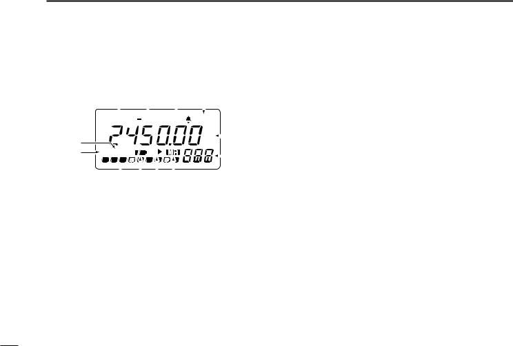
t FREQUENCY READOUT
Shows the operating frequency, set mode contents, etc.
•The smaller “75,” “50” and “25” to the right of the readout indicate 7.5, 5.0 and 2.5 kHz, respectively.
•The decimal point of the frequency flashes during scan.
y MEMORY CHANNEL READOUT (p. 7)
Shows the memory channel number, 8 memory banks (A–H), etc.
•The 1st digit (A–H) of regular memory indicates memory bank.
•‘tV0’ to ‘tV9’ indicate AM TV memory channels. (p. 35)
•‘t00’ to ‘t49’ indicate FM TV memory channels. (p. 36)
•Suffix ‘A’ and ‘b’ indicate scan edge memory channels.
u MEMORY MODE INDICATOR (p. 7)
Appears when a memory channel is selected.
4
i SKIP SCAN INDICATOR (pgs. 22, 24)
“"” appears when the selected memory channel is set as a skip channel in memory mode.
“P"” shows that the skip frequency function is turned ON or OFF in VFO mode.
“P"” appears when the selected memory channel is set to be skipped during VFO scan (full, band and programmed scan) in memory mode.
o BATTERY INDICATORS
Both segments appear when the batteries have enough capacity.
Only the right segment appears when the batteries are nearing exhaustion.
•“Low V” appears when battery replacement is necessary and the color LCD is ON.
•The U.S.A. version automatically turns itself OFF when the receiver detects that battery replacement is necessary.
!0S (SIGNAL) INDICATORS
Show the relative signal strength while receiving.
!1BUSY INDICATOR
“RX” appears when receiving a signal or when the squelch is open.
PANEL DESCRIPTION 2
!2ATTENUATOR INDICATOR (p. 9)
Appears when the attenuator function is in use.
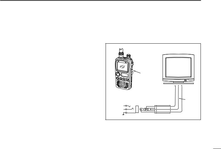
• Audio and video output jack information
|
|
Television |
|
To [A/V OUT] |
|
|
|
|
|
Video |
Audio |
|
3-conductor |
|
|
[A/V OUT] |
3.5 (d) mm (1⁄8˝) |
Ground |
|
connector |
|
||
Audio |
|
||
|
|
|
|
Video |
|
|
|
Ground |
|
|
|
• Video output impedance |
: 75 Ω |
, 1 V p-p typical |
|
• Audio output impedance |
: 1 kΩ |
, 300 mV rms typical |
|
5
2 PANEL DESCRIPTION
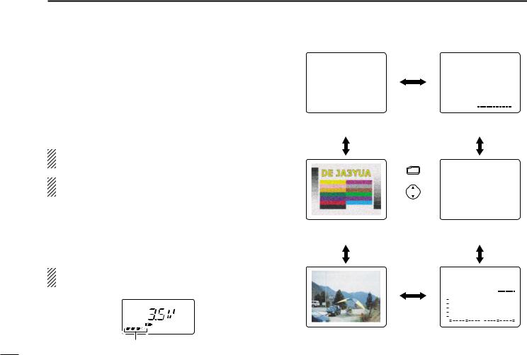
■ Dual LCD
The receiver has dual LCDs for versatile display selection.
The color LCD has 5 screens and 1 optional screen as follows:
simple, multi-function, band scope, direction finding, TV (frequency selection) and amateur TV* screen.
*Amateur TV screen can be selected for the ATV-type and 1200/2400 MHz bands only.
The color LCD can be used when the operating frequency is 30 MHz and above.
qPush [FUNC] + [↕] for 2 sec. to turn the color LCD ON, if desired.
wPush [FUNC] + [↕] momentarily one or more times to toggle the screen of the color LCD.
While the color LCD is in use, the sub LCD displays the voltage of the power source.
RX
Appears when simple screen is selected.
FM |
|
PSKIP |
FM |
|
|
|
|
|
|
|
|
|
|
|
|
PSKIP |
||||||||||||
|
|
|
|
|
|
|
|
|
|
|
|
|
|
|
|
|
|
|
|
|
|
|
|
|
|
|
|
|
|
|
|
|
|
|
|
|
|
|
|
|
|
|
|
146.100.000 |
|||||||||||||
TS |
146.100.000 |
TS |
|
|
|
|
|
|
15.0 |
|
|
|
||||||||||||||||
15.0 |
RX |
|
|
|
|
|
|
|
|
|
|
|
|
|
|
|
|
|
||||||||||
|
|
|
|
S1 |
3 |
|
|
5 |
|
7 9 |
|
|||||||||||||||||
|
|
|
|
|
|
|
|
|
|
|
|
|
|
|
|
|
|
|
|
|
|
|
|
|
|
|
|
|
|
|
|
|
|
|
|
|
|
|
|
|
|
|
|
|
|
|
|
|
|
|
|
|
|
|
|
|
|
Simple screen |
VOL |
|
|
|
|
|
|
|
|
|
|
|
|
|
|
|
|
|
||||||||||
|
|
|
|
|
|
|
|
|
|
|
|
|
|
|
|
|
||||||||||||
|
|
|
Multi-function |
|||||||||||||||||||||||||
|
|
|
|
|
|
screen |
|
|
|
|
|
|
|
|
|
|
|
|||||||||||
|
|
FUNC |
FM |
|
|
|
|
|
|
|
|
|
|
|
|
PSKIP |
||||||||||||
|
|
|
|
|
|
|
|
|
|
|
|
|
|
|
|
|
|
|
|
|
|
|
|
|
|
|
|
|
|
+ |
|
|
|
|
|
|
|
|
|
|
|
|
|
|
|
|
|
|
|
|
|
|
|||||
|
146.100.000 |
|||||||||||||||||||||||||||
|
|
|
TS |
|
|
|
|
|
|
15.0 |
|
|
|
|||||||||||||||
|
|
momentarily |
|
|
|
|
|
|
|
|
|
|
|
|
|
|
|
|
|
|
|
|
|
|
|
|
|
|
|
|
|
|
|
|
|
|
|
|
|
|
|
|
|
|
|
|
|
|
|
|
|
|
|
|
|||
ATV screen (p. 36; |
|
Direction finding |
||||||||||||||||||||||||||
ATV type, 1200/2400 MHz bands only) |
|
screen (p. 37) |
||||||||||||||||||||||||||
|
|
|
FM |
|
|
|
|
|
|
|
|
|
|
|
|
PSKIP |
||||||||||||
|
|
|
146.100.000 |
|
TS= 15.0 |
|||||||||||||||||||||||
|
|
|
S1 3 |
5 |
7 9 |
|
SWEEP10K |
|||||||||||||||||||||
|
|
|
RX |
|
|
|
|
|
|
|
|
|
|
|
|
VOL |
|
|
|
|
|
|
|
|
||||
|
|
|
|
|
|
|
|
|
|
|
|
|
|
|
|
|
|
|
|
|||||||||
|
|
|
|
|
|
|
|
|
|
|
|
|
|
|
|
|
|
|
|
|
|
|
|
|
|
|
|
|
|
|
|
|
|
|
|
|
|
|
|
|
|
|
|
|
|
|
|
|
|
|
|
|
|
|
|
|
|
|
|
|
|
|
|
|
|
|
|
|
|
|
|
|
|
|
|
|
|
|
|
|
|
|
|
|
|
|
|
|
|
|
|
|
|
|
|
|
|
|
|
|
|
|
|
|
|
|
|
|
|
|
|
|
|
|
|
|
|
|
|
|
|
|
|
|
|
|
|
|
|
|
|
|
|
|
|
|
|
|
|
|
|
|
|
|
|
|
|
|
|
|
|
|
|
|
|
|
|
|
|
|
|
|
|
|
|
|
|
|
|
|
|
|
|
|
|
|
|
|
|
|
|
|
|
|
|
|
|
|
|
|
|
|
|
|
|
|
|
|
|
|
|
|
|
|
|
|
|
|
|
|
|
|
|
|
|
|
|
|
|
|
|
|
|
|
|
|
|
|
|
|
|
|
|
|
|
|
|
|
|
|
|
|
|
|
|
|
|
|
|
|
|
|
|
|
|
|
|
|
|
|
|
|
|
|
|
|
|
|
|
|
|
|
|
|
|
|
|
|
|
|
|
|
|
|
|
|
|
|
|
|
|
|
|
|
|
|
|
|
|
|
|
|
|
|
|
|
|
|
|
|
|
|
|
|
|
|
|
|
|
|
|
|
|
|
|
|
|
|
|
|
|
|
|
|
|
|
|
|
|
|
|
|
|
|
|
|
|
TV screen (p. 34; |
Band scope |
frequency selection) |
screen (p. 33) |
6
FREQUENCY AND CHANNEL SETTING 3 
■ VFO and memory channels
This receiver has 2 normal operating modes: VFO mode and memory mode.
VFO mode is used for setting a desired frequency within the frequency coverage.
Push [V/M] to select VFO mode.
Memory mode is used for operation of memory channels which have programmed frequencies.
Push [V/M] to select memory mode.
•“X” or “M:” appears when a memory channel is selected.
•To program a memory, refer to p. 14.
•TV band and ATV (ATV type) have separate memory channels (pgs. 35, 36)
What is VFO?
FM
 P
P
FM
 P
P


“” or “M:” appears.
FM |
PSKIP |
M:A00
145.000.000 TS 15.0
VFO is an abbreviation of Variable Frequency Oscillator. Frequencies for receiving are generated and controlled by the VFO.
■ Operating band selection
The receiver can receive the broadcast band, HF band, 50 MHz band, FM broadcast band, VHF avionics band, 144 MHz band, 300 MHz band, 400 MHz band, 800 MHz band,* 1200 MHz, 2400 MHz or TV band.
*Some frequencies cannot be received with the U.S.A. version.
Push [↔] several times to select the desired band.
•When a memory channel is selected, the first push of [↔] selects VFO mode.
Amateur TV screen is also selected for the ATV-type IC-R3. (p. 36)
0.495–1.620 MHz
1.625–29.995 MHz
30.0–75.995 MHz
76.0–107.995 MHz
108.0–135.995 MHz
136.0–255.095 MHz
255.1–382.095 MHz
382.1–769.795 MHz
769.8–960.095 MHz
960.1–1399.995 MHz
1400.0–2450.095 MHz
TV band (CH selection)
7
3 FREQUENCY AND CHANNEL SETTING
■ Setting a frequency
q Select the desired band with [↔].
wRotate [DIAL] to change the frequency.
•The frequency changes according to the preset tuning steps. See the right section for selecting the tuning step.
•Some TV channels may be set as skip channels by default and can be selected by rotating [DIAL] while pushing [FUNC]. (p. 34).
•Push [↔] while pushing [FUNC] to change the frequency in 100 kHz, 1 MHz or 10 MHz steps.
FM


 75
75 
 50
50 


 25
25
FM


 75
75 
 50
50 


 25
25
[DIAL] changes the frequency according to the selected tuning step.
While pushing [FUNC], [DIAL] changes the frequency in 1 MHz steps (default).
The 1 MHz tuning step (dial select step) can be set to 100 kHz, 1 MHz or 10 MHz tuning steps in set mode. See p. 39 for details.
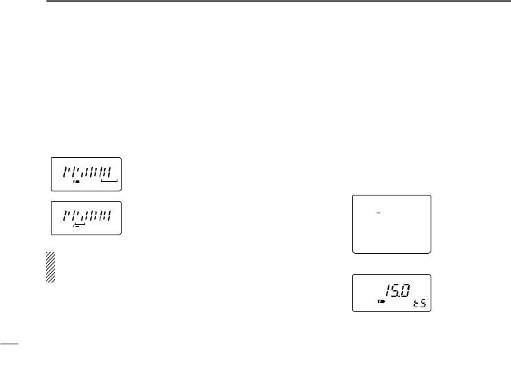
■ Setting a tuning step
Tuning steps can be selected for each band, however, the tuning step of the broadcast band is fixed to 9 kHz steps except for U.S.A. and Canada versions. The following are available.
• 5 kHz |
• 6.25 kHz* • 10 kHz |
• 12.5 kHz |
• 15 kHz |
• 20 kHz |
• 25 kHz • 30 kHz |
• 50 kHz |
• 100 kHz |
* Not available for 1200 MHz band.
q Select the desired band, except for TV band, with [↔].
wRotate [DIAL] while pushing [MODE] to select the desired tuning step.
•15 kHz tuning step (Simple screen)
FM
146.100.000 TS 15.0
•15 kHz tuning step (Sub LCD)
8
■ Selecting a memory channel
q Push [V/M] to select memory |
FM |
|
mode. |
||
|
||
• “X” or “M:” appears when a mem- |
P |
|
|
ory channel is selected.
wRotate [DIAL] to change the indicated memory channel.
•Only programmed memory channels can be selected.
•Rotate [DIAL] while pushing [FUNC] to change the memory bank.
[DIAL] changes the memory channel.
FM
 P
P


While pushing [FUNC], [DIAL] changes the memory bank.
■ Lock function
The lock function prevents accidental frequency changes and accidental function access.
Push [FUNC] + [MODE] for 2 sec. to toggle the lock func-
tion ON and OFF.
•[POWER], [↕ (VOL)] and [SQL] can still be accessed while the lock function is ON (default).
•Accessible switches can be set to 1 of 4 groups in set mode. See p. 42 for details.
FM
“L ” appears when the lock function is in use.
FREQUENCY AND CHANNEL SETTING 3
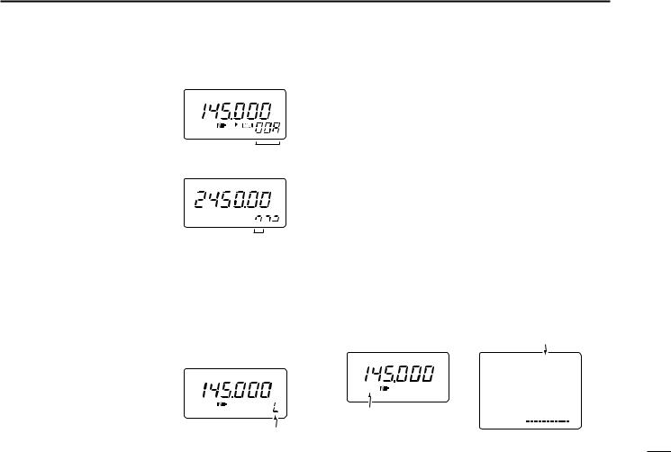
■ Attenuator function
The attenuator prevents a desired signal from distorting when very strong signals are near the desired frequency or when very strong electric fields, such as from a broadcasting station, are near your location.
The receiver has 4 attenuation levels for various operating conditions. The attenuator functions when the operating frequency is 1149.995 MHz or below.
qPush [FUNC] + [(SQL) ATT] to enter the attenuator setting condition.
wRotate [DIAL] to set the attenuation level 1–4 or turn the attenuator function OFF.
•“ATT1” – “ATT4” appears in the color LCD when the color LCD is ON; “ATT” appears in the sub display when the color LCD is OFF.
e Push [(SQL) ATT] to exit the attenuator setting condition.
|
Shows when the attenuator |
||||||||
|
(level 4) is in use. |
|
|||||||
FM |
FM |
|
|
|
|
ATT4 |
|
||
|
|
|
|
|
|
|
|
||
|
|
|
|
145.000.000 |
|||||
ATT |
TS |
|
|
|
15.0 |
|
|||
Shows when the attenuator |
S1 |
3 |
5 |
7 |
9 |
||||
|
|
|
|
|
|
|
|
|
|
is in use. |
VOL |
|
|
|
|
|
|
|
|
|
|
|
|
|
|
|
|||
|
|
|
|
|
|
|
|||
9
 4 BASIC OPERATION
■ Receiving
Make sure a charged battery pack or alkaline batteries are installed. (pgs. 1, 46)
q Push [POWER] for 2 sec. to turn power ON.
wPush [↕] to set the desired audio level.
•One of the LCDs shows the volume level while setting. See the next page for details.
e Push [↔] to select an operating band. (p. 7)
r Rotate [DIAL] to set an operating frequency. (p. 8)
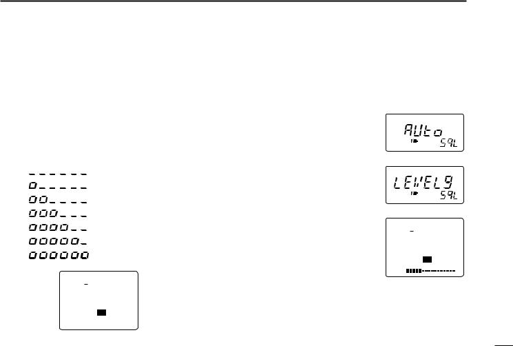
tSet the squelch level.
•While pushing [SQL], rotate [DIAL].
•The first click of [DIAL] indicates the current squelch level.
•“LEVEL1” is loose squelch and “LEVEL9” is tight squelch.
•“AUTO” indicates automatic level adjustment with a noise pulse count system.
•Push and hold [SQL] to open the squelch manually. (default behaviour; p. 41)
yWhen a signal is received:
Squelch opens and audio is emitted from the speaker.
The S indicators show the relative signal strength.
The busy indicator appears when receiving a signal or when the squelch is open.
For U.S.A. version
The U.S.A. version automatically turns itself OFF when the receiver detects that battery replacement is necessary. Replace the battery or charge the battery pack in this case.
r Set frequency  t Set the squelch
level
w Set volume |
|
|
e Select band |
t Push for setting |
|
|
||
q Power switch |
the squelch |
|
(Push to monitor) |
||
|
For non-U.S.A. versions
If the display mode selection is set as ‘manual’ (p. 43) with the color LCD ON, the receiver may not be able to turn itself OFF when the battery becomes exhausted.
Replace the battery and turn power OFF in this case.
10
■ Setting volume level
The audio level can be adjusted through 32 levels.
Push [↕] to set the desired audio level.
•Beep tone sounds while setting. This indicates the approximate sound level. (default behaviour; p. 40)
•Pushing and holding these keys changes the audio level continuously.
•One of the LCDs shows the volume level while setting.
INDICATION
AUDIO LEVEL
(Sub LCD)
Min. setting (no audio)
:
Initial setting
:
:
:
Max. setting
FM
146.100.000
TS 15.0
S1 3 5 7 9
VOL 


 Volume level
BASIC OPERATION 4
■ Setting squelch level
The squelch circuit mutes the received audio signal depending on the signal strength. The receiver has 9 squelch levels, a continuously open setting and an automatic squelch setting.
While pushing [SQL], rotate the [DIAL] to select the squelch level.
•The first click of [DIAL] indicates the current squelch level.
•“LEVEL1” is loose squelch and “LEVEL9” is tight squelch.
•“AUTO” indicates automatic level adjustment with a noise pulse count system.
•“OPEN” indicates continuously open setting.
Automatic squelch
Maximum level
FM
146.100.000
TS 15.0
S1 3 5 7 9
VOL
level 5
11
4 BASIC OPERATION
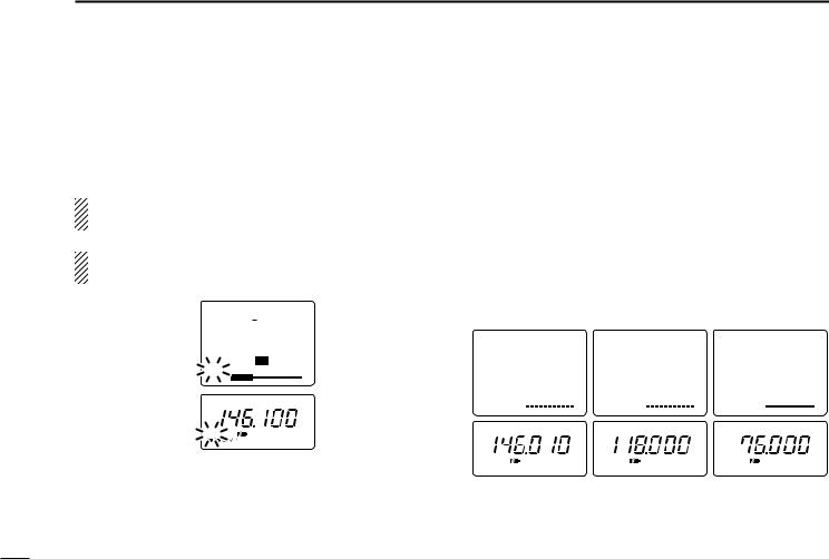
■ Monitor function
This function is used to listen to weak signals or to open the tone squelch manually.
Push and hold [SQL] to monitor the operating frequency.
•“RX” flashes while monitoring.
The [SQL] switch can be set to ‘sticky’ operation in set mode. (p. 41)
You can monitor duplex communication by pushing the [SQL] switch when the duplex function is in use. (p. 31)
FM
146.100.000
TS 15.0
S1 3 5 7 9
RX 


VOL
FM
RX
■ Receive mode selection
Receive modes are determined by the physical properties of the radio signals. The receiver has 3 receive modes: FM, AM and WFM modes. TV and ATV (ATV type only) also use WFM mode. The mode selection is stored independently in each band and memory channels.
Typically, AM mode is used for the AM broadcast stations (0.495–1.620 MHz) and air band (118–135.995 MHz), and WFM is used for FM broadcast stations (76–107.9 MHz).
Push [MODE] one or more times to select the desired receive mode.
FM |
|
|
|
AM |
|
|
|
WFM |
|
|
|
||||||||||||||||||||||||||||||
|
|
|
|
|
|
|
|
|
|
|
|
|
|
|
|
|
|
|
|
|
|
|
|
|
|
|
|
|
|
|
|
|
|
|
|
|
|
||||
146.010.000 |
118.000.000 |
76.000.000 |
|||||||||||||||||||||||||||||||||||||||
TS |
15.0 |
TS |
25.0 |
TS |
50.0 |
||||||||||||||||||||||||||||||||||||
S1 3 |
|
|
7 9 |
S1 3 |
|
|
7 9 |
S1 3 |
|
|
7 9 |
||||||||||||||||||||||||||||||
5 |
5 |
5 |
|||||||||||||||||||||||||||||||||||||||
VOL |
|
|
|
|
|
|
|
|
|
|
|
|
|
VOL |
|
|
|
|
|
|
|
|
|
|
|
|
|
VOL |
|
|
|
|
|
|
|
|
|
|
|
|
|
|
|
|
|
|
|
|
|
|
|
|
|
|
|
|
|
|
|
|
|
|
|
|
|
||||||||||||||||||
FM |
|
|
|
AM |
|
|
|
WFM |
|
|
|
||||||||||||||||||||||||||||||
FM mode AM mode WFM mode
12
TV screens cannot be selected by pushing [MODE]. See p. 34 for TV operation details.
WFM |
WFM |
RX |
RX |
TV screen |
FM TV mode |
frequency selection |
(ATV type only) |
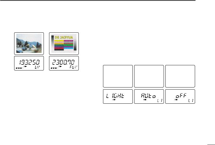
■ Display backlighting
The receiver has display backlighting with a 5 sec. timer for nighttime operation. The display backlighting can be turned ON continuously or turned OFF, if desired.
Push any switch except [FUNC]; or, rotate [DIAL] to turn the backlighting ON.
•When auto backlighting is set, the backlighting will automatically turn OFF when switches and [DIAL] have not been operated for 5 sec.
BASIC OPERATION 4
◊Setting the backlighting condition
qPush [FUNC] + [(MODE) SET] momentarily to enter set mode.
• Select a non-band scope screen in advance for color LCD.
wRotate [DIAL] until “LIGHT” appears.
•“LIGHt” disappears after 1 sec. and the previously selected backlighting timer and “LI” appears when color LCD is OFF.
ePush [↔] or rotate the tuning dial while pushing [FUNC] to select the desired backlighting condition.
r Push [(MODE) SET] to exit set mode.
Pause Scan |
: 10SEC |
|
Priority |
: |
OFF |
Beep Audio |
: VOLUME |
|
Light |
: |
AUTO |
A.Power OFF |
: |
OFF |
Pause Scan |
: 10SEC |
|
Priority |
: |
OFF |
Beep Audio |
: VOLUME |
|
Light |
: |
AUTO |
A.Power OFF |
: |
OFF |
Pause Scan |
: 10SEC |
|
Priority |
: |
OFF |
Beep Audio |
: VOLUME |
|
Light |
: |
OFF |
A.Power OFF |
: |
OFF |
Backlighting set |
Automatic backlighting Continuously OFF |
mode |
|
13
 5 MEMORY CHANNELS
■ General
The receiver has 400 memory channels in 8 banks (A–H) for storage of often-used frequencies.
◊Memory channel contents
The following information can be programmed into memory channels:
•Operating frequency (p. 8)
•Receive mode (p. 12)
•Tuning step (p. 8)
•Memory name (p. 17)
•Duplex direction (DUP or –DUP) with an offset frequency (p. 31)
•Tone squelch ON/OFF (p. 28)
•Tone squelch frequency (p. 28)
•Scan skip setting (p. 22)
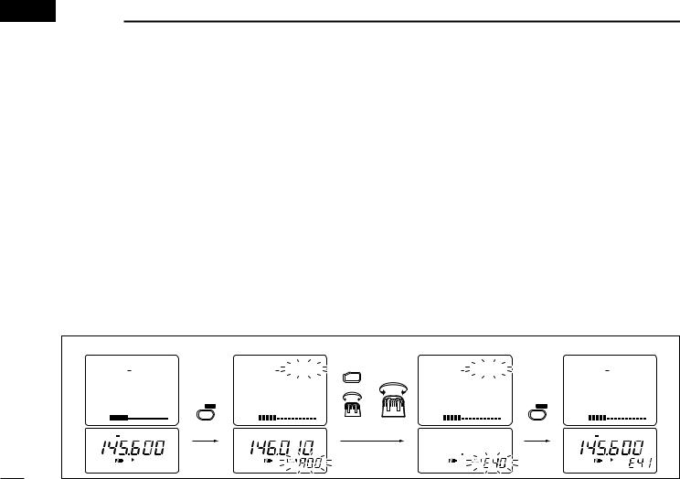
■ Programming during selection
q Push [↔] to select an operating band.
wSet the desired frequency:
Set the frequency using [DIAL].
Set other data (e.g. offset frequency, duplex direction,
tone squelch frequency, etc.), if required.
ePush [V/M] for 1 sec. to indicate memory channels.
•Do not hold [V/M] for more than 2 sec., otherwise the previously selected memory channel will be overwritten.
rRotate [DIAL] to select the desired channel.
•VFO (VF), as well as regular memory channels, can be programmed in this way.
•Rotate [DIAL] while pushing [FUNC] to select a memory bank (A–H), programmed scan edge channel or VFO (VF).
tPush [V/M] for 1 sec. to program.
•Keep pushing for 2 sec. or more to automatically select the next memory channel, if desired.
[EXAMPLE]: Programming ch 40 of memory bank E during selection (and ch 41 selection).
FM |
–DUP TSQL PSKIP |
|
FM |
M:A00 |
|
|
M:E40 |
|
FM |
–DUP TSQL PSKIP |
|
|
|
|
|
|
|
|
E41 |
||
145.600.000 |
|
146.010.000 |
FUNC |
|
. . |
|
145.600.000 |
|||
TS |
15.0 |
|
TS |
15.0 |
+ |
TS |
. |
|
TS |
15.0 |
S1 3 5 7 9 |
V/M SKIP |
S1 3 5 7 9 |
|
S1 3 5 7 9 |
V/M SKIP |
S1 3 5 7 9 |
||||
VOL |
|
VOL |
|
for bank |
VOL |
|
|
VOL |
||
|
|
for 1 sec. |
|
|
for CH |
|
for 2 sec. |
|
|
|
|
FM DUP TSQL |
FM |
|
selection |
selection |
|
|
FM DUP TSQL |
||
|
|
|
|
|
|
|||||
|
|
|
|
|
|
|
|
|||
|
P |
|
|
|
|
|
|
blank |
|
P |
|
|
|
|
|
|
|
|
channel |
|
|
14
MEMORY CHANNELS 5
■ Programming after selection
q Select memory mode with [V/M].
wSet the memory channel to be programmed with [DIAL].
•Rotate [DIAL] while pushing [FUNC] to select a memory bank (A–H) or programmed scan edge channel.
•Non-programmed channels cannot be selected.
e Push [V/M] to select VFO mode.
rSet the desired frequency:
Select the desired band with [↔].
Set the frequency using [DIAL].
Set other data (e.g. offset frequency, duplex direction,
tone squelch frequency, etc.), if required.
tPush [V/M] for 2 sec. to program the selected channel.
•Keep pushing for 2 sec. or more to automatically select the next memory channel, if desired.
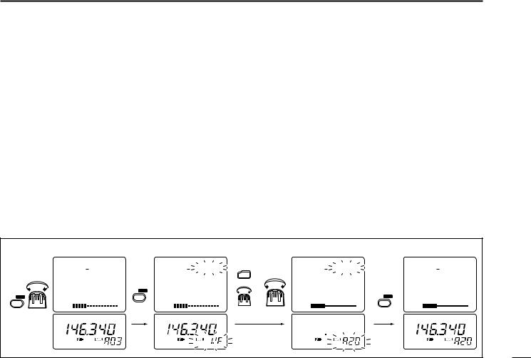
■Transferring memory contents to another memory
q Select memory mode with [V/M].
wSelect the memory channel to transfer with [DIAL].
•Rotate [DIAL] while pushing [FUNC] to select a memory bank (A–H) or programmed scan edge channel.
ePush [V/M] for 1 sec. to indicate memory channels.
•Do not hold [V/M] for more than 2 sec., otherwise the memory channel contents will be transferred to VFO.
rRotate [DIAL] to select the channel to transfer to.
•Rotate [DIAL] while pushing [FUNC] to select a memory bank or programmed scan edge channel.
•VFO (VF), as well as regular memory channels, can be transferred in this way.
t Push [V/M] for 2 sec. to transfer.
[EXAMPLE]: Transferring memory channel 3 (memory bank A) to 20 (memory bank A).
|
FM |
M:A03 |
|
FM |
M: VF |
|
|
M:A20 |
|
FM |
M:A20 |
|
|
|
|
|
|
|
|
||||
|
146.340.000 |
|
146.340.000 |
FUNC |
|
. . |
|
146.340.000 |
|||
|
TS |
15.0 |
|
TS |
15.0 |
+ |
TS |
. |
|
TS |
15.0 |
|
S1 3 5 7 9 |
V/M SKIP |
S1 3 5 7 9 |
|
S1 3 5 7 9 |
|
S1 3 5 7 9 |
||||
V/M SKIP |
|
|
V/M SKIP |
||||||||
|
VOL |
|
for |
VOL |
|
|
VOL |
|
|
VOL |
|
Select memory |
|
|
|
|
for bank |
for CH |
|
for 2 sec. |
|
|
|
|
|
1 sec. |
|
|
|
|
|
||||
|
|
|
|
selection |
selection |
|
|
|
|||
channel |
FM |
|
|
FM |
|
|
|
FM |
|
||
|
|
|
|
|
|
|
|
||||
blank channel
15
5 MEMORY CHANNELS
■ Memory bank selection |
■ Memory clear |
The receiver has 400 memory channels in 8 banks (A–H) for storage of often-used frequencies.
q Select memory mode with [V/M].
wRotate [DIAL] while pushing [FUNC] to select the desired memory banks.
e Rotate [DIAL] to select the desired memory channel.
FM FM FM
Memory bank A Memory bank G Memory bank H
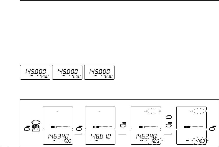
Unwanted memory channels can be cleared (erased). Before clearing a memory channel, make sure it is no longer needed as cleared memories cannot be recalled.
q Select memory mode with [V/M].
wSet the memory channel to be cleared with [DIAL].
•Rotate [DIAL] while pushing [FUNC] to select a memory bank (A–H) or programmed scan edge channel.
eSelect VFO mode with [V/M] and push [V/M] for 1 sec. to indicate the selected memory channel.
•Do not hold [V/M] for more than 2 sec., otherwise the selected memory channel will be overwritten.
rPush [FUNC] + [V/M] for 2 sec. to clear.
•3 beeps sound, then the frequency is cleared. t Push [MODE] to return to VFO mode.
[EXAMPLE]: Clearing memory channel 3 (memory bank A).
|
FM |
M:A03 |
FM |
|
|
FM |
M:A03 |
|
|
M:A03 |
|
|
146.010.000 |
|
|
|
|
||||
|
146.340.000 |
|
146.340.000 |
|
|
. . |
||||
|
TS |
15.0 |
TS |
15.0 |
|
TS |
15.0 |
FUNC |
TS |
. |
|
S1 3 5 7 9 |
S1 3 5 7 9 |
|
S1 3 5 7 9 |
+ |
S1 3 5 7 9 |
||||
|
V/M SKIP |
V/M SKIP |
||||||||
V/M SKIP |
VOL |
|
V/M SKIP VOL |
|
|
VOL |
|
|
VOL |
MODE SET |
|
FM |
|
FM |
|
for 1 sec. |
FM |
|
for 2 sec. |
|
|
Select memory |
|
|
|
|
|
|
|
|||
channel |
|
|
|
|
|
|
|
|
|
|
16
 Loading...