


INSTRUCTION MANUAL
VHF TRANSCEIVER
iF50
UHF TRANSCEIVER
iF60
This device complies with Part 15 of the FCC rules. Operation is subject to the condition that this device does not cause harmful interference.

SAFETY TRAINING INFORMATION
Your Icom radio generates RF electromagnetic energy during transmit mode. This radio is designed for and classified as “Occupational Use Only”, meaning it must be used only during the course of employment by individuals aware of the hazards, and the ways to minimize such hazards. This radio is NOT intended for use by the “General Population” in an uncontrolled environment.
This radio has been tested and complies with the FCC RF exposure limits for “Occupational Use Only”. In addition, your Icom radio complies with the following Standards and Guidelines with regard to RF energy and electromagnetic energy levels and evaluation of such levels for exposure to humans:
•FCC OET Bulletin 65 Edition 97-01 Supplement C, Evaluating Compliance with FCC Guidelines for Human Exposure to Radio Frequency Electromagnetic Fields.
•American National Standards Institute (C95.1-1992), IEEE Standard for Safety Levels with Respect to Human Exposure to Radio Frequency Electromagnetic Fields, 3 kHz to 300 GHz.
•American National Standards Institute (C95.3-1992), IEEE Recommended Practice for the Measurement of Potentially Hazardous Electromagnetic Fields– RF and Microwave.
•The following accessories are authorized for use with this product. Use of accessories other than those specified may result in RF exposure levels exceeding the FCC requirements for wireless RF exposure.; Belt Clip (MB-98), Rechargeable Li-Ion Battery Pack (BP-227), Alkaline Battery Case (BP-226) and Speaker-microphone (HM-138).
To ensure that your expose to RF electromagnetic energy is within the FCC allowable limits for occupational use, always adhere to the following guidelines:
CAU TION
i
•DO NOT operate the radio without a proper antenna attached, as this may damaged the radio and may also cause you to exceed FCC RF exposure limits. A proper antenna is the antenna supplied with this radio by the manufacturer or antenna specifically authorized by the manufacturer for use with this radio.
•DO NOT transmit for more than 50% of total radio use time (“50% duty cycle”). Transmitting more than 50% of the time can cause FCC RF exposure compliance requirements to be exceeded. The radio is transmitting when the “TX indicator” lights red. You can cause the radio to transmit by pressing the “PTT” switch.
•ALWAYS keep the antenna at least 2.5 cm (1 inch) away from the body when transmitting and only use the Icom belt-clip which is listed on page vi when attaching the radio to your belt, etc., to ensure FCC RF exposure compliance requirements are not exceeded. To provide the recipients of your transmission the best sound quality, hold the antenna at least 5 cm (2 inches) from your mouth, and slightly off to one side.
The information listed above provides the user with the information needed to make him or her aware of RF exposure, and what to do to assure that this radio operates with the FCC RF exposure limits of this radio.
Electromagnetic Interference/Compatibility
During transmissions, your Icom radio generates RF energy that can possibly cause interference with other devices or systems. To avoid such interference, turn off the radio in areas where signs are posted to do so. DO NOT operate the transmitter in areas that are sensitive to electromagnetic radiation such as hospitals, aircraft, and blasting sites.
Occupational/Controlled Use
The radio transmitter is used in situations in which persons are exposed as consequence of their employment provided those persons are fully aware of the potential for exposure and can exercise control over their exposure.
ii

FOREWORD
READ ALL INSTRUCTIONS carefully and completely before using the transceiver.
SAVE THIS INSTRUCTION MANUAL— This instruction manual contains important operating instructions for the IC-F50 VHF TRANSCEIVER and IC-F60 UHF TRANSCEIVER.
EXPLICIT DEFINITIONS
WORD |
DEFINITION |
RWARNING
Personal injury, fire hazard or electric shock may occur.
CAUTION Equipment damage may occur.
NOTE
If disregarded, inconvenience only. No risk of personal injury, fire or electric shock.
OPERATING NOTES
•When transmitting with a portable radio, hold the radio in a vertical position with its microphone 5 to 10 centimeters (2 to 4 inches) away from your mouth. Keep the antenna at least 2.5 centimeters (1 inch) from your head and body.
•If you wear a portable two-way radio on your body, ensure that the antenna is at least 2.5 centimeters (1 inch) from your body when transmitting.
PRECAUTION
R WARNING! NEVER hold the transceiver so that the antenna is very close to, or touching exposed parts of the body, especially the face or eyes, while transmitting. The transceiver will perform best if the microphone is 5 to 10 cm (2 to 4 inches) away from the lips and the transceiver is vertical.
R WARNING! NEVER operate the transceiver with a headset or other audio accessories at high volume levels.
CAUTION! NEVER short the terminals of the battery pack.
NEVER connect the transceiver to a power source other than the BP-226 or BP-227. Such a connection will ruin the transceiver.
DO NOT push the PTT when not actually desiring to transmit.
AVOID using or placing the transceiver in direct sunlight or in areas with temperatures below –30°C (–22°F) or above +60°C (+140°F).
DO NOT modify the transceiver for any reason.
MAKE SURE the flexible antenna and battery pack are securely attached to the transceiver, and that the antenna and battery pack are dry before attachment. Exposing the inside of the transceiver to water will result in serious damage to the transceiver.
The use of non-Icom battery packs/chargers may impair transceiver performance and invalidate the warranty.
FCC caution:
Changes or modifications to this device, not expressly approved by Icom Inc., could void your authority to operate this transceiver under FCC regulations.
iii |
iv |

TABLE OF CONTENTS
SAFETY TRAINING INFORMATION …………………………………… i FOREWORD ……………………………………………………………… iii EXPLICIT DEFINITIONS ………………………………………………… iii OPERATING NOTES …………………………………………………… iii PRECAUTION …………………………………………………………… iv TABLE OF CONTENTS ………………………………………………… v SUPPLIED ACCESSORIES …………………………………………… vi
1 ACCESSORIES ……………………………………………………… 1–2
‘Accessory attachments ……………………………………………… 1
2 PANEL DESCRIPTION …………………………………………… 3–11
‘Front, top and side panels ………………………………………… 3
‘Function display ……………………………………………………… 6
‘Programmable function keys ……………………………………… 7
3 CONVENTIONAL OPERATION ………………………………… 12–18
‘Turning power ON ………………………………………………… 12
‘Channel selection ………………………………………………… 12
‘Call procedure ……………………………………………………… 13
‘ Receiving and transmitting ……………………………………… 14
‘Scrambler function ………………………………………………… 17
‘User set mode ……………………………………………………… 18
4 BIIS OPERATION ………………………………………………… 19–34
‘Default setting ……………………………………………………… 19
‘Receiving a call …………………………………………………… 20
‘Transmitting a call ………………………………………………… 23
‘Receiving a message ……………………………………………… 26
‘Transmitting a status ……………………………………………… 29
‘Transmitting an SDM ……………………………………………… 30
‘Position data transmission ………………………………………… 31
‘Printer connection ………………………………………………… 32
‘PC connection ……………………………………………………… 32
‘Digital ANI …………………………………………………………… 32
‘Auto emergency transmission …………………………………… 33
‘Stun function………………………………………………………… 33
‘BIIS indication ……………………………………………………… 34
‘ Priority A channel selection ……………………………………… 34
v
5 BATTERY CHARGING ………………………………………… 35–44
‘Battery charging …………………………………………………… 35
‘Caution ……………………………………………………………… 36
‘Optional battery chargers ………………………………………… 37
‘Optional battery case ……………………………………………… 43
6 SPEAKER-MICROPHONE ……………………………………… 45–46
‘Optional HM-138 description ……………………………………… 45
‘Attachment ………………………………………………………… 46
7 OPTIONS ………………………………………………………… 47–48
SUPPLIED ACCESSORIES |
|
The following accessories are supplied: |
Qty. |
• Flexible antenna . . . . . . . . . . . . . . . . . . . . . . . . . . . . . . . . . . |
. . .1 |
• Battery pack . . . . . . . . . . . . . . . . . . . . . . . . . . . . . . . . . . . . . |
. . .1 |
• Jack cover . . . . . . . . . . . . . . . . . . . . . . . . . . . . . . . . . . . . . . . . |
. .1 |
• Belt clip . . . . . . . . . . . . . . . . . . . . . . . . . . . . . . . . . . . . . . . . . . |
. .1 |
• Function name stickers* (KEY-STICKER) . . . . . . . . . . . . . . . . |
. .1 |
*There are no names on the programmable function keys since the functions can be freely assigned to [P0] to [P3], [Red], [ ] and [
 ] keys.
Attach the supplied function name stickers above the appropriate keys for easy recognition of that key’s assigned function.
vi

1 ACCESSORIES
■ Accessory attachments
D Flexible antenna
Connect the supplied flexible antenna to the antenna connector.
CAUTION!
• NEVER HOLD by the antenna when carrying the transceiver.
• Transmitting without an antenna may damage the transceiver.
ï Battery pack
To attach the battery pack:
Slide the battery pack on the back of the transceiver in the direction of the arrow (q), then lock it with the battery release button.
•Slide the battery pack until the battery release button makes a ‘click’ sound.
To release the battery pack:
Push the battery release button in the direction of the arrow (w) as shown below. The battery pack is then released.
NEVER release or attach the battery pack when the transceiver is wet or soiled. This may result water or dust getting into the transceiver/battery pack and may result in the transceiver being damaged.
1
Battery pack
q
w
Battery release button
ACCESSORIES 1
ï Jack cover
Attach the jack cover when the optional speaker-microphone is not
used. |
|
To attach the jack cover: |
To detach the jack cover: |
q Insert the jack cover into the |
e Unscrew the screw with a |
[SP MIC] connector. |
phillips screwdriver. |
w Tighten the screw. |
r Detach the jack cover for the |
|
speaker-microphone connec- |
|
tion. |
q
r
 e
e
w
D Belt clip
Attach the belt clip to the back of the transceiver with the supplied screws.
 Supplied screws
1
2

2 PANEL DESCRIPTION
■ Front, top and side panels
|
w |
|
q |
e |
|
|
||
|
r |
|
i |
Speaker |
|
(See the following |
||
|
||
|
NOTE.) |
|
u |
Microphone |
|
Function display |
||
|
||
|
(p. 6) |
|
|
t |
y
NOTE: If the speaker netting (for dust proofing) becomes wet, dry it with a hair drier (cool mode) etc. before operating the transceiver. Otherwise the audio may be difficult to hear for loss of the sound pressure.
PANEL DESCRIPTION |
2 |
q VOLUME CONTROL [VOL] |
2 |
Turns power ON and adjusts the audio level.
w RED BUTTON
The desired function can be assigned by your dealer.
e ANTENNA CONNECTOR
Connects the supplied antenna.
r SPEAKER-MICROPHONE CONNECTOR [SP MIC]
Connects the optional speaker-microphone. (p. 46)
[SP MIC] jack cover
NOTE: KEEP the [SP MIC] jack cover attached to the transceiver when the speakermicrophone is not used.
(See p. 2 for details)
t DEALER-PROGRAMMABLE KEYS [P0] to [P3]
The desired functions can be assigned independently by your dealer.
y CH UP AND DOWN KEYS [ ]/[
]/[ ]
]
During standby condition, push to select an operating channel.
After pushing [TX Code CH Select], push to select a TX code channel.
After pushing [DTMF Autodial], push to select a DTMF channel.
After pushing and holding [Scan A Start/Stop]/[Scan B Start/Stop], push to select a scan group.
After pushing [Digital], push to select a BIIS code, status num-
ber or SDM.
*Desired functions can be assigned independently by your dealer.
Continue to the next page.
3 |
4 |
2 PANEL DESCRIPTION
Front, top and side panels (Continued)
u TRANSMIT/BUSY INDICATOR
Lights red while transmitting; lights green while receiving a signal, or when the squelch is open.
i PTT SWITCH [PTT]
Push and hold to transmit; release to receive.
PANEL DESCRIPTION 2
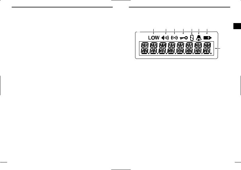
■ Function display
q w e r t y u |
2 |
i |
q OUTPUT POWER INDICATOR
Appears when Low 2 or Low 1 is selected.
w AUDIBLE INDICATOR
Appears when the channel is in the ‘audible’ (unmute) condition.
Appears when the specified 2/5-tone/BIIS code is received.
e COMPANDER INDICATOR
Appears when the compander function is activated.
r KEY LOCK INDICATOR
Appears during the key lock function ON.
t SCRAMBLER INDICATOR
Appears when the voice scrambler function is activated.
y BELL INDICATOR
Appears/blinks when the specific 2/5-tone/BIIS code is received, according to the programming.
u BATTERY INDICATOR
Appears or blinks when the battery power decreases to a specified level.
i ALPHANUMERIC DISPLAY
Displays the operating channel number, channel names, Set mode contents, DTMF numbers, etc.
5 |
6 |

2 PANEL DESCRIPTION
■ Programmable function keys
The following functions can be assigned to [P0], [P1], [P2], [P3], [Red], [ ] and [
 ] programmable function keys.
Consult your Icom dealer or system operator for details concerning your transceivers programming.
If the programmable function names are bracketed in the following explanations, the specific switch used to activate the function depends on programming.
CH UP AND DOWN KEYS
•Select an operating channel.
•Select a transmit code channel after pushing the [TX Code CH Select] keys.
•Select a DTMF channel after pushing the [DTMF Autodial] key.
•Select a scan group after pushing and holding the [Scan A Start/Stop]/[Scan B Start/Stop] keys.
•Select a BIIS code, status number or SDM after pushing the [Digital] key.
BANK SELECT KEY
Push this key, then push [CH Up] or [CH Down] to select the desired bank.
SCAN START/STOP KEYS
Push this key to start scanning; and push again to stop.
Push and hold this key to indicate the scan group, then select the desired scan group using [CH Up]/[CH Down].
SCAN TAG KEY
Adds or deletes the selected channel to the scan group.
PANEL DESCRIPTION |
2 |
|
PRIORITY CHANNEL KEYS |
|
|
Push to select Priority A or Priority B channel. |
|
|
Push and hold [Prio A (Rewrite)] to rewrite the Prio A channel. |
|
2 |
|
|
|
MR-CH 1/2/3/4 KEYS
Select an operating channel directly.
MONITOR KEY
Mute and release the CTCSS (DTCS) or 2-tone squelch mute. Open any squelch/deactivate any mute while pushing this key. (LMR operation only)
Activates one of (or two of) the following functions on each channel independently: (PMR or BIIS PMR operation only)
•Push and hold to un-mute the channel (audio is emitted; ‘Audible’ condition).
•Push to mute the channel (sets to ‘Inaudible’ only).
•Push to un-mute the channel (sets to ‘Audible’ only).
•Push after the communication is finished to send a ‘reset code’.
NOTE: The un-mute condition (‘Audible’ condition) may automatically return to the mute condition (‘Inaudible‘ condition) after a specified period.
LOCK KEY
Push and hold to electronically lock all programmable keys except the following:
[Call] (incl. Call A and Call B), [Moni(Audi)] and [Emergency] keys.
OUTPUT POWER SELECTION KEY
Select the transmit output power temporarily or permanently, depending on the pre-setting.
• Ask your dealer for the output power level for each selection.
7 |
8 |

2 PANEL DESCRIPTION
C.TONE CHANNEL ENTER KEY
Select the continuous tone channel using [CH Up]/[CH Down] keys to change the tone frequency/code setting after pushing this key for permanent operation.
TALK AROUND KEY
Turn the talk around function ON and OFF.
•The talk around function equalizes the transmit frequency to the receive frequency for transceiver-to-transceiver communication.
WIDE/NARROW KEY
Push to toggle the IF bandwidth between wide and narrow.
•The wide passband width can be selected from 25.0 or 20.0 kHz using the CS-F50 CLONING SOFTWARE. (PMR or BIIS PMR operation only) Ask your dealer for details.
DTMF AUTODIAL KEY
Push to enter the DTMF channel selection mode. Then select the desired DTMF channel using [CH Up]/[CH Down] keys.
After selecting the desired DTMF channel, push this key to transmit the DTMF code.
DTMF RE-DIAL KEY
Push to transmit the last-transmitted DTMF code.
CALL KEYS
Push to transmit a 2/5-tone/BIIS ID code.
•Call transmission is necessary before you call another station depending on your signalling system.
•The [Call A] and/or [Call B] keys may be available when your system employs selective ‘Individual/Group’ calls. Ask your dealer which call is assigned to each key.
PANEL DESCRIPTION 2
EMERGENCY KEYS
Push and hold to transmit an emergency call.
When [Emergency Single (Silent)] or [Emergency Repeat 2 (Silent)] is pushed, an emergency call is transmitted without a beep emission and LCD indication change.
•If you want to cancel the emergency call, push (or push and hold) the key again before transmitting the call.
•The emergency call is transmitted one time only or repeatedly until receiving a control code depending on the pre-setting.
TX CODE ENTER KEY (PMR or BIIS PMR operation only)
Push to enter the direct ID code edit mode, for both 5-tone and MSK. Then set the desired digit using [CH Up]/[CH Down]/ [TX Code CH Up]/[TX Code CH Down]. (p. 16)
TX CODE CHANNEL SELECT KEY
Push to enter the direct ID code channel selection mode. Then set the desired channel using [CH Up]/[CH Down]/[TX Code CH Up]/[TX Code CH Down]. (p. 15)
While in ID code channel selection mode, push for 1 sec. to enter the ID code edit mode for 5-tone and MSK. Then set the desired digit using [CH Up]/[CH Down]/[TX Code CH Up]/[TX Code CH Down]. (p. 16)
TX CODE CHANNEL UP/DOWN KEYS
Push to select a TX code channel directly.
ID MEMORY READ KEY (PMR or BIIS PMR operation only)
Recalls detected ID codes.
•Push this key, then push [CH Up]/[CH Down] for selection.
•Up to 5 ID’s are memorized.
Push and hold to erase the selected memorized ID’s.
9 |
10 |
 Loading...