


INSTRUCTION MANUAL
VHF/UHF
ALL MODE TRANSCEIVER
i910H

IMPORTANT
READ THIS INSTRUCTION MANUAL CAREFULLY before attempting to operate the transceiver.
SAVE THIS INSTRUCTION MANUAL. This manual contains important safety and operating instructions for the IC-910H.
EXPLICIT DEFINITIONS
WORD |
DEFINITION |
RWARNING |
Personal injury, fire hazard or electric |
|
shock may occur. |
CAUTION |
Equipment damage may occur. |
|
|
NOTE |
If disregarded, inconvenience only. |
No risk of personal injury, fire or |
|
|
electric shock. |
PRECAUTIONS
RWARNING HIGH VOLTAGE! NEVER attach an antenna or internal antenna connector during transmission. This may result in an electrical shock or burn.
RNEVER apply AC to the [DC13.8V] jack on the transceiver rear panel. This could cause a fire or ruin the transceiver.
RNEVER apply more than 16 V DC, such as a 24 V battery, to the [DC13.8V] jack on the transceiver rear panel. This could cause a fire or ruin the transceiver.
RNEVER let metal, wire or other objects touch any internal part or connectors on the rear panel of the transceiver. This may result in an electric shock.
RNEVER expose the transceiver to rain, snow or any liquids.
AVOID using or placing the transceiver in areas with temperatures below –10°C (+14°F) or above +60°C (+140°F). Be aware that temperatures on a vehicle’s dashboard can exceed 80°C (+176°F), resulting in permanent damage to the transceiver if left there for extended periods.
AVOID placing the transceiver in excessively dusty environments or in direct sunlight.
AVOID placing the transceiver against walls or putting anything on top of the transceiver. This will obstruct heat dissipation.
Place unit in a secure place to avoid inadvertent use by children.
During mobile operation, DO NOT operate the transceiver without running the vehicle’s engine. When the transceiver power is ON and your vehicle’s engine is OFF, the vehicle’s battery will soon become exhausted.
Make sure the transceiver power is OFF before starting the vehicle. This will avoid possible damage to the transceiver by ignition voltage spikes.
During maritime mobile operation, keep the transceiver and microphone as far away as possible from the magnetic navigation compass to prevent erroneous indications.
BE CAREFUL! The heatsink will become hot when operating the transceiver continuously for long periods.
BE CAREFUL! If a linear amplifier is connected, set the transceiver’s RF output power to less than the linear amplifier’s maximum input level, otherwise, the linear amplifier will be damaged.
Use Icom microphones only (supplied or optional). Other manufacturer’s microphones have different pin assignments, and connection to the IC-910H may damage the transceiver.
i
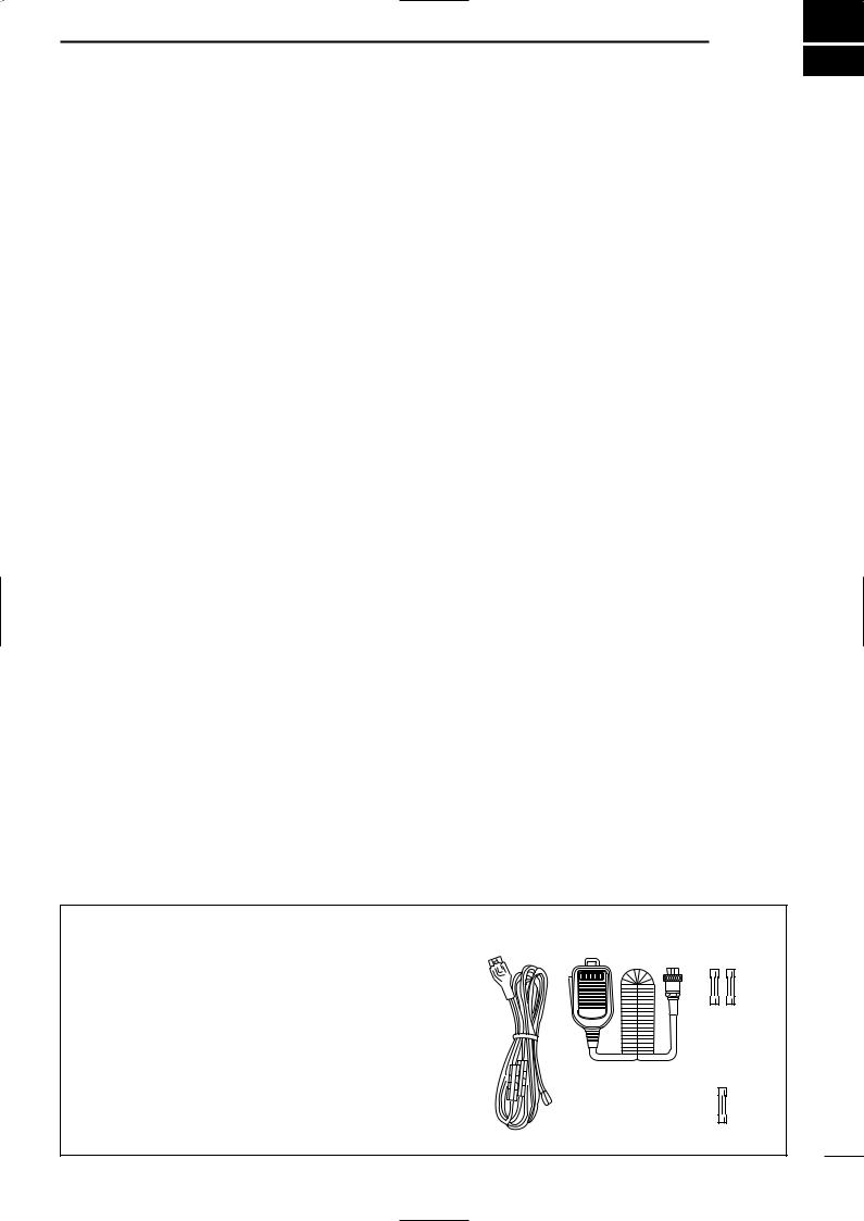
TABLE OF CONTENTS 1
IMPORTANT ........................................ |
i |
|
EXPLICIT DEFINITIONS ..................... |
i |
|
PRECAUTIONS ................................... |
i |
|
1 |
TABLE OF CONTENTS ................ |
1 |
2 |
PANEL DESCRIPTION ........... |
2 – 13 |
|
■ Front panel ..................................... |
2 |
|
■ Function display ........................... |
10 |
|
■ Rear panel .................................... |
12 |
3 |
INSTALLATION AND |
|
|
CONNECTIONS ................... |
14 – 17 |
|
■ Unpacking .................................... |
14 |
|
■ Grounding ..................................... |
14 |
|
■ Selecting a location ...................... |
14 |
|
■ Antenna connection ...................... |
14 |
|
■ Required connections ................... |
15 |
|
■ Advanced connections ................. |
16 |
|
■ Power supply connections ............ |
17 |
4 |
BASIC OPERATION ............. |
18 – 25 |
|
■ Initial settings ................................ |
18 |
|
■ When first applying power |
|
|
(CPU resetting) ............................. |
18 |
|
■ MAIN and SUB bands .................. |
19 |
|
■ Operating band selection ............. |
20 |
|
■ VFO description ............................ |
21 |
|
■ Frequency setting ......................... |
22 |
|
■ SUB band OFF ............................. |
24 |
|
■ SUB tuning dial ............................. |
24 |
|
■ Dial lock function .......................... |
25 |
5 |
RECEIVE AND TRANSMIT .. |
26 – 39 |
|
■ Functions for receive .................... |
26 |
|
■ RIT function .................................. |
27 |
|
■ IF shift function ............................. |
27 |
|
■ AGC time constant ....................... |
28 |
|
■ AFC function ................................. |
28 |
|
■ FM center indicator ....................... |
28 |
|
■ Attenuator ..................................... |
29 |
|
■ Simple band scope ....................... |
29 |
|
■ Noise blanker ............................... |
30 |
|
■ Tone squelch operation ................ |
30 |
|
■ Optional DSP functions ................ |
31 |
|
■ Functions for transmit ................... |
32 |
|
■ Transmit via microphone .............. |
32 |
|
■ Indications during transmit ........... |
|
32 |
|
■ FM mode operation ...................... |
|
33 |
|
■ VOX operation .............................. |
|
33 |
|
■ Repeater operation ....................... |
|
34 |
|
■ SSB mode operation .................... |
|
36 |
|
■ Speech compressor ..................... |
|
36 |
|
■ Split frequency operation .............. |
|
37 |
|
■ Full duplex operation .................... |
|
37 |
|
■ Connections for CW ..................... |
|
38 |
|
■ CW mode operation ..................... |
|
38 |
6 |
MEMORY OPERATION ........ |
40 – 44 |
|
|
■ Memory channels ......................... |
|
40 |
|
■ Operation on a memory channel .. |
40 |
|
|
■ Programming in VFO mode .......... |
|
41 |
|
■ Programming in memory mode .... |
41 |
|
|
■ Blank channels ............................. |
|
42 |
|
■ Frequency transferring ................. |
|
42 |
|
■ Memory clearing ........................... |
|
43 |
|
■ Call channels ................................ |
|
43 |
|
■ Memo pads ................................... |
|
44 |
7 |
SCANS ................................. |
45 – 47 |
|
|
■ Scan types .................................... |
|
45 |
|
■ Preparation ................................... |
|
45 |
|
■ Programmed scan operation ........ |
|
46 |
|
■ Memory scan operation ................ |
|
46 |
|
■ Memory select scan ..................... |
|
47 |
|
■ Tone scan ..................................... |
|
47 |
8 |
SATELLITE OPERATION ..... |
48 – 51 |
|
|
■ Satellite communications outline .. |
48 |
|
|
■ Satellite notes ............................... |
|
48 |
|
■ Entering into the satellite mode .... |
48 |
|
|
■ Setting the satellite VFO ............... |
|
49 |
|
■ Tracking selection ......................... |
|
49 |
|
■ Preparation ................................... |
|
50 |
|
■ Satellite operation ......................... |
|
51 |
|
■ Satellite memory ........................... |
|
51 |
9 |
DATA COMMUNICATION ..... |
52 – 54 |
|
|
■ Functions for AFSK ...................... |
|
52 |
|
■ Connections for AFSK .................. |
|
52 |
|
■ Operating mode notes .................. |
|
53 |
|
■ Operating frequency notes ........... |
|
53 |
|
■ AFSK operation ............................ |
|
53 |
|
■ Setting the ACC socket ................ |
|
54 |
10 SET MODE ........................... |
55 – 69 |
|
■ Set mode description .................... |
|
55 |
■ General set mode ......................... |
|
56 |
■ FM set mode ................................ |
|
60 |
■ SSB/CW set mode ....................... |
|
62 |
■ Scan set mode ............................. |
|
64 |
■ Memo pad set mode ..................... |
|
64 |
■ Compressor set mode .................. |
|
64 |
■ VOX set mode .............................. |
|
65 |
■ Attenuator set mode ..................... |
|
65 |
■ Transmit set mode ........................ |
|
66 |
■ NR set mode ................................ |
|
67 |
■ SWP set mode ............................. |
|
67 |
■ RIT/SHIFT set mode .................... |
|
68 |
■ Speech set mode ......................... |
|
69 |
11 OPTION INSTALLATIONS ... |
70 – 76 |
|
■ Internal view ................................. |
|
70 |
■ Opening the transceiver’s case .... |
71 |
|
■ UT-102 VOICE SYNTHESIZER |
|
|
UNIT .............................................. |
|
71 |
■ UT-106 DSP UNIT .......................... |
|
72 |
■ UX-910 1200 MHz BAND UNIT ........ |
|
73 |
■ CR-293 HIGH STABILITY CRYSTAL |
|
|
UNIT .............................................. |
|
74 |
■ FL-132/FL-133 CW NARROW |
|
|
FILTER ........................................... |
|
75 |
12 MAINTENANCE ................... |
76 – 77 |
|
■ Troubleshooting ............................ |
|
76 |
■ Fuse replacement ......................... |
|
77 |
■ CPU resetting ............................... |
|
77 |
13 CONTROL COMMAND ........ |
78 – 79 |
|
■ Remote jack (CI-V) information .... |
78 |
|
14 SPECIFICATIONS ....................... |
|
80 |
15 OPTIONS ..................................... |
|
81 |
16 INSTALLATION NOTES ....... |
82 – 83 |
|
SUPPLIED ACCESSORIES
The transceiver comes with the following accessories. |
q |
w |
e |
|
|
Qty. |
|
|
|
q DC power cable (OPC-657A) |
............................ 1 |
|
|
|
w Hand microphone (HM-12) ................................ |
1 |
|
|
|
e Spare fuses (FGB 30 A) .................................... |
2 |
|
|
|
r Spare fuse (FGB 4 A) ........................................ |
1 |
|
|
|
|
|
|
|
r |
1
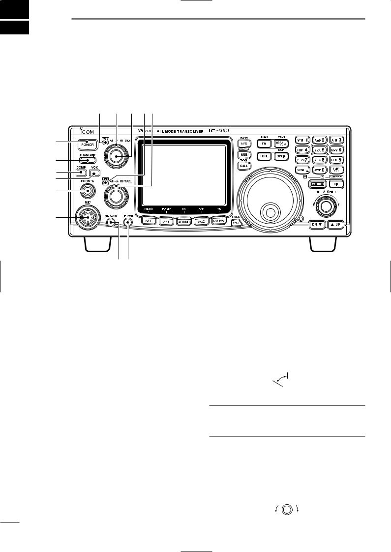
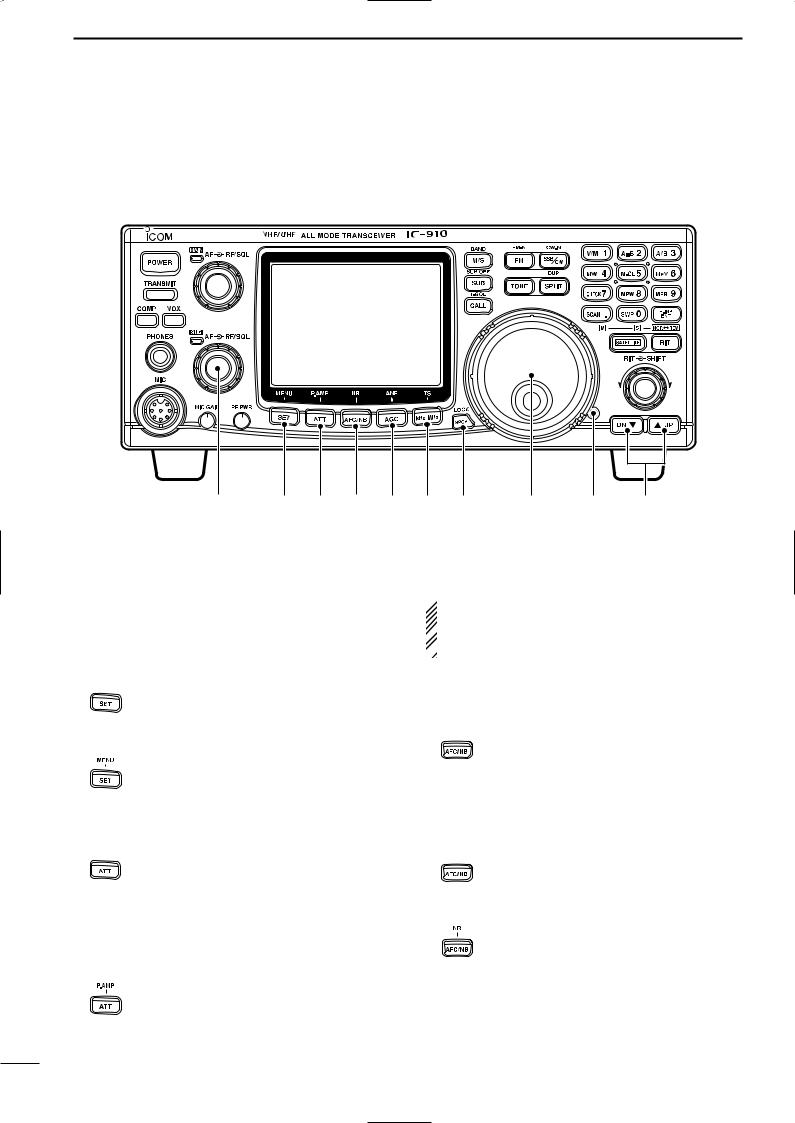
2 PANEL DESCRIPTION
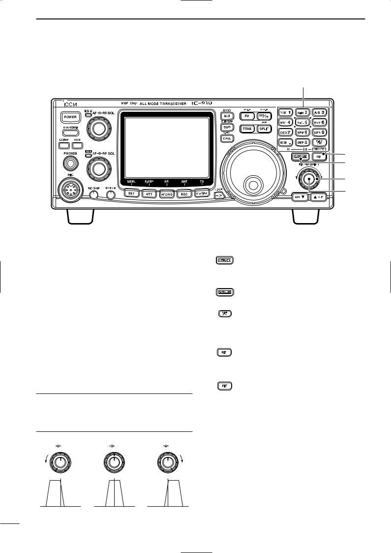
■ Front panel
o |
!0 !1 !2!3 |
q |
|
w |
|
e |
|
r |
|
t |
|
y |
|
|
u i |
q POWER SWITCH [POWER]
Push momentarily to turn power ON.
Push for 2 sec. to turn power OFF.
w TRANSMIT SWITCH [TRANSMIT]
Push to select transmitting or receiving.
e COMPRESSION SWITCH [COMP] (p. 36)
Push to switch the speech compressor function ON and OFF.
•The speech compressor increases average RF output power, improving signal strength and readability in SSB.
r VOX SWITCH [VOX] (p. 33)
Push to switch the VOX function ON and OFF.
•The VOX (Voice-Operated Transmission) function toggles between transmit and receive with your voice. This function provides an opportunity to input log entries into your computer, etc., while operating.
t HEADPHONE JACK [PHONES]
Accepts headphones.
•Output power: 5 mW with 8–16 Ω load.
•When headphones are connected, the internal speaker or connected external speaker does not function.
•The MAIN and SUB band audio can be mixed or separated when using stereo headphones according to set mode settings. (p. 57)
y MICROPHONE CONNECTOR [MIC]
Accepts the supplied or optional microphone.
•See p. 81 for appropriate microphones.
•See p. 15 for microphone connector information.
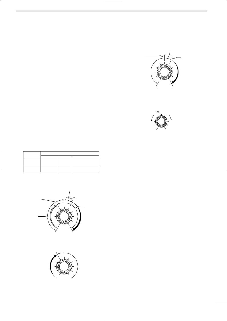
u MIC GAIN CONTROL [MIC GAIN]
Adjusts microphone input gain.
Recommended level for an Icom microphone
MIC GAIN
Decreases 

 Increases
How to set the microphone gain.
Set the [MIC] control so that the [MAIN]/[SUB] indicator (ALC indicator) some times lights brighter during normal voice transmission in SSB mode.
i RF POWER CONTROL [RF PWR]
Continuously varies the RF output power from min-
imum to maximum. |
|
|
144 MHz band |
5–100 W |
|
430(440) MHz band |
5–75 W |
|
1200 MHz band |
1–10 W (optional UX-910) |
|
RF PWR |
||
Decreases |
|
Increases |
|
||
|
||
2
o MAIN BAND INDICATOR [MAIN]
Lights green while the squelch is opened or a signal is received on the MAIN band; lights red while transmitting on the MAIN band.
•While transmitting, the indicator also shows ALC condition. Brightness increases more than usual when the ALC function is activated.
Flashes when an off-frequency signal is received and the FM center detector is activated. (p. 28)
!0RF GAIN CONTROL/SQUELCH CONTROL [RF/SQL] (outer control)
Adjusts the RF gain and squelch threshold level for the MAIN band. The squelch removes noise output from the speaker (closed condition) when no signal is received.
•The squelch is particularly effective for FM. It is also available for other modes.
•12 to 13 o’clock position is recommended for any setting of the [RF/SQL] control.
•The squelch threshold position for SSB/CW mode can be set from 12 or 13 o’clock position in SSB/CW set mode. (p. 62)
•The control can be set as ‘Auto’ (RF gain control in SSB and CW; squelch control in FM) or squelch control (RF gain is fixed at maximum) in set mode as follows. (p. 56)
MODE |
SET MODE SETTING |
|||
AUTO |
SQL |
RF GAIN + SQL |
||
|
||||
SSB, CW |
RF GAIN |
SQL |
RF GAIN + SQL |
|
FM |
SQL |
SQL |
SQL |
|
• When setting as RF gain/squelch control
|
Noise squelch (FM mode) |
Squelch is |
Recommended level |
|
|
open. |
Maximum |
|
|
|
RF gain |
RF gain |
|
adjustable |
S-meter |
range (SSB, |
squelch |
CW modes) |
|
•When functioning as RF gain control
(Squelch is fixed open; SSB, CW only)
Maximum
RF gain
Adjustable range
Minimum RF gain 
PANEL DESCRIPTION 2
•When functioning as squelch control
(RF gain is fixed at maximum.)
Noise squelch
Noise squelch
threshold
S-meter squelch threshold
Squelch is |
S-meter |
|
squelch |
||
open. |
||
|
||
Shallow |
Deep |
!1AF CONTROL [AF] (inner control)
Varies the audio output level from the speaker for the MAIN band.
AF |
RF/SQL |
Decreases |
Increases |
No audio output |
Max. audio output |
!2SUB BAND INDICATOR [SUB]
Lights green while the squelch is opened or a signal is received on the SUB band; lights red while transmitting in satellite operation.
!3RF GAIN CONTROL/SQUELCH CONTROL [RF/SQL] (outer control)
Adjusts the RF gain and squelch threshold level for the SUB band. The squelch removes noise output from the speaker (closed condition) when no signal is received.
3
2 PANEL DESCRIPTION
■ Front panel (continued)
!4 |
!5 !6 !7 !8 !9 @0 |
@1 |
@2 |
@3 |
!4AF CONTROL [AF] (inner control)
Varies the audio output level from the speaker for the SUB band.
!5SET•MENU SWITCH [SET•MENU] (p. 55)
Push this switch then one of [FM], [SSB/CW], [RIT], [SCAN], [NR], [TRANSMIT], [COMP], [VOX], [ATT], [SWP], [MPW] or [SPCH] to enter the indepen-
dent item set mode.
Push for 1 sec. to enter the set mode for commonly used item settings.
For 1 sec.
!6ATTENUATOR•PRE-AMP SWITCH [ATT•P.AMP]
Push to switch the attenuator function ON and OFF. (p. 29) Use this function to protect from signal distortion from excessively strong signals.
•The attenuation level is independently adjustable for 144 MHz or 430(440) MHz band in the ATT set mode. The optional 1200 MHz band attenuation level is fixed and is approx. 20 dB. (p. 65)
|
Push for 1 sec. to switch the connected |
|
|
pre-amplifier ON and OFF, when an op- |
|
For 1 sec. |
tional pre-amplifier unit, AG-25, AG-35 |
|
and/or AG-1200, is connected. (p. 16) |
||
|
 DO NOT connect any equipment, such as an SWR
or power meter between the transceiver and pream-
 plifier. In such case, the preamplifier may not acti-
  vate properly.
!7AUTO FREQUENCY CONTROL/NOISE BLANKER•NOISE REDUCTION SWITCH [AFC/NB•NR]
During FM/FM narrow mode operation, push to switch the AFC (Automatic Frequency Control) function ON and OFF. (p. 28)
•Automatically tunes the operating frequency, when an off-frequency signal is received, in 100 kHz steps. This function also follows the signal even if the frequency is shifted.
During SSB or CW mode operation, push to switch the noise blanker function ON and OFF. (p. 30)
•Reduces pulse-type noise, such as ignition noise from a vehicle.
|
Push for 1 sec. to switch the noise re- |
|
|
duction function ON and OFF when an |
|
For 1 sec. |
optional DSP unit, UT-106, is installed. |
|
(p. 31) |
||
|
•Reduces unwanted noise and pulls out the desired signal only for clear readability.
4
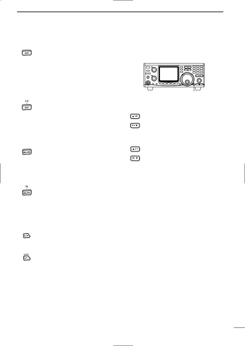
!8AUTO GAIN CONTROL•AUTO NOTCH FILTER SWITCH [AGC•ANF]
Push to switch the time constant of the automatic gain control to SLOW and FAST for the MAIN band.* (p. 28)
•SLOW selection (“FAGC” disappears) during SSB (USB or LSB) operation, FAST selection (“FAGC” appears) during CW, data operation
and while tuning with fast tuning dial rotation are recommended.
*The AGC time constant can be selected on the MAIN band only. FAST selection is fixed on the SUB band.
Push for 1 sec. to switch the automatic
notch filter function ON and OFF when
For 1 sec. the optional DSP unit, UT-106, is installed. (p. 31)
•Reduces interference signals such as beat, RTTY or CW signals and the notch frequency automatically follows the interfering signal.
!9kHz/MHz•TUNING STEP SELECTION SWITCH [kHz/MHz] (p. 22)
Push to select tuning step for the tuning dial or scanning from 1 kHz, 1 MHz step and regular tuning step* in sequence
•“Z” appears above the 1 kHz or 1 MHz digit when 1 kHz or 1 MHz tuning step is selected, respectively.
*The regular tuning step is selected for each operating mode as follows.
Push for 1 sec. to enter the regular tuning step selection mode.
For 1 sec.
• The tuning step can be selected for each operating mode independently.
•SSB/CW mode: 1, 10, 50 and 100 Hz step; FM mode: 0.1, 5, 6.25, 10, 12.5, 20, 25 and 100 kHz step can be selected by rotating the tuning dial.
@0SPEECH•LOCK SWITCH [SPCH•LOCK]
Announces the receiving signal strength and/or selected readout frequency when the optional UT-102 is installed. (pgs. 69,
71)
Push for 1 sec. to switch the tuning dial lock function ON and OFF to prevent accidental setting changes. (p. 25)
@1TUNING DIAL
Changes the displayed frequency, selects set mode items, etc.
PANEL DESCRIPTION 2
@2BRAKE ADJUSTMENT SCREW
Adjust the tension of the tuning dial.
•Rotate clockwise to increase the tension; counterclockwise to decrease the tension.
Brake adjustment screw
@3MEMORY CHANNEL UP/DOWN SWITCHES
[Y UP]/[DOWN Z] (p. 40)
|
Push [Y UP] to change the memory |
or |
channel up; push [DOWN Z] to change |
|
the memory channel down. |
•Memory channel changes continuously while holding either switch.
•Memory channels can be selected both in VFO and memory modes.
or
For 1 sec.
5
2 PANEL DESCRIPTION
■ Front panel (continued)
@8 |
@7 |
@6 |
@5 |
@4 |
@4RIT CONTROL [RIT] (p. 27)
Shifts the receive frequency without changing the transmit frequency for the MAIN band only while the RIT function is activated.
• SSB/CW mode |
: ±1.0 kHz* in 10 Hz step |
• FM mode |
: ±5.0 kHz* in 50 Hz step |
*For 1200 MHz band; ±2.0 kHz and ±10.0 kHz, respectively when the optional UX-910 is installed.
•By using the Sub dial function, the RIT control can be used as the MAIN/SUB tuning dial or the SUB band IF shift control. See page 24 for details.
@5IF SHIFT CONTROL [SHIFT]
Shifts the center frequency of the receiver’s IF passband within 1.2 kHz range.
•By using the Sub dial function, the IF shift control can be used as the MAIN/SUB tuning dial or the SUB band IF shift control. See page 24 for details.
What is the Sub dial function?
The [RIT] and [SHIFT] controls are used for RIT and IF shift controls for the MAIN band by default. However, the Sub dial function assigns these controls as the MAIN/SUB tuning dial or the SUB band IF shift control. (p. 24, 68)
RIT |
SHIFT |
RIT |
SHIFT |
RIT |
SHIFT |
@6SATELLITE SWITCH [SATELLITE]
Push to enter satellite mode (RX on MAIN, TX on SUB band). Push again to return to the condition before entering into the satellite mode.
Push to enter satellite mode using the current operating frequencies when
For 1 sec. |
pushing for 1 sec. |
•To change the normal and reverse satellite operations, push [F-INP/ENT] for 1 sec.
For 1 sec.
@7RIT SWITCH [RIT] (p. 27)
Push to switch the RIT control activity ON and OFF.
•“RIT” indicator appears when the RIT function is in use.
Push for 1 sec. to switch the Sub dial function ON and OFF.
For 1 sec. •“RIT” indicator flashes and the [RIT] and [SHIFT] controllers acts as the controllers specified in the RIT/SHIFT set mode. (p. 68)
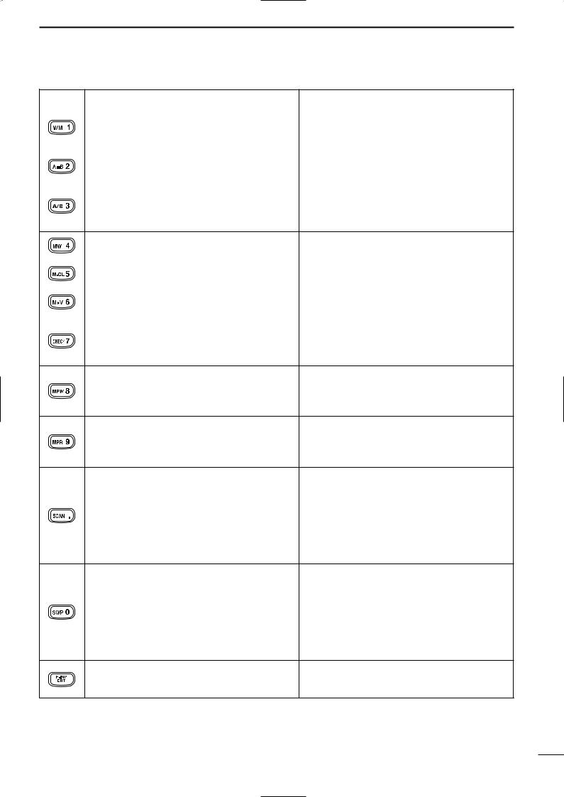
@8KEYPAD
Numeral and other function keys for tuning and activating functions.
See the table at right.
Max. counter- |
Center position |
Max. clockwise |
clockwise position |
|
position |
6
PANEL DESCRIPTION 2
Switch |
Switch action when pushed |
Switch action when pushed for 1 sec. |
|
• Enters numeral “1” when entering an operating |
|
|
frequency. (p. 23) |
|
|
• Switches between VFO and memory mode. |
|
|
(p. 40) |
|
|
|
|
|
Enters numeral “2” when entering an operating |
Equalizes the condition of the VFO A and B. |
|
frequency. (p. 23) |
(p. 21) |
|
|
|
|
• Enters numeral “3” when entering an operating |
Shows 10 Hz and 1 Hz digits of operating fre- |
|
frequency. (p. 23) |
quency on both the MAIN and SUB bands while |
•Switches between VFO A and B during VFO pushing and holding. (p. 22) mode operation. (p. 21)
Enters numeral “4” when entering an operating |
Stores the set conditions into a memory channel. |
frequency. (p. 23) |
(p. 41) |
|
|
Enters numeral “5” when entering an operating |
Clears stored contents of memory channel to be |
frequency. (p. 23) |
a blank channel. (p. 43) |
|
|
Enters numeral “6” when entering an operating |
Transfers the contents of a memory channel into |
frequency. (p. 23) |
either the VFO A or B. (p. 42) |
|
|
Enters numeral “7” when entering an operating |
Opens squelch for monitoring the operating or |
frequency. (p. 23) |
transmit frequency, and the frequency indication |
|
automatically changes to transmit frequency in the |
|
case of duplex or split operation. (p. 34) |
•Enters numeral “8” when entering an operating frequency. (p. 23)
•Stores the displayed operating conditions into MEMO PAD channel (p. 44)
•Enters numeral “9” when entering an operating frequency. (p. 23)
•Re-calls the contents in the MEMO PAD channel. (p. 44)
•Enters decimal point “.” for entering below the Starts and cancels tone scan when the repeater “MHz“ digits when entering an operating fretone or tone squelch is activated in FM (narrow)
quency. |
operation. (p. 47) |
•Starts and cancels scanning function. (p. 46)
•Turns OFF the SUB band frequency indication during satellite operation. In this case, only the MAIN band frequency can be tuned by rotating the tuning dial. (p. 49)
•Enters numeral “0” when entering an operating frequency. (p. 23)
•Switches sweep function for the bandscope ON and OFF. (p. 29)
•Turns OFF the MAIN band frequency indication during satellite operation. In this case, only the SUB band frequency can be tuned by rotating the tuning dial. (p. 49)
Enables operating frequency entering from the Used to change memory channel during memory keypad. See page 23 for details. mode operation by rotating the tuning dial while
pushing and holding. (p. 40)
7
2 PANEL DESCRIPTION
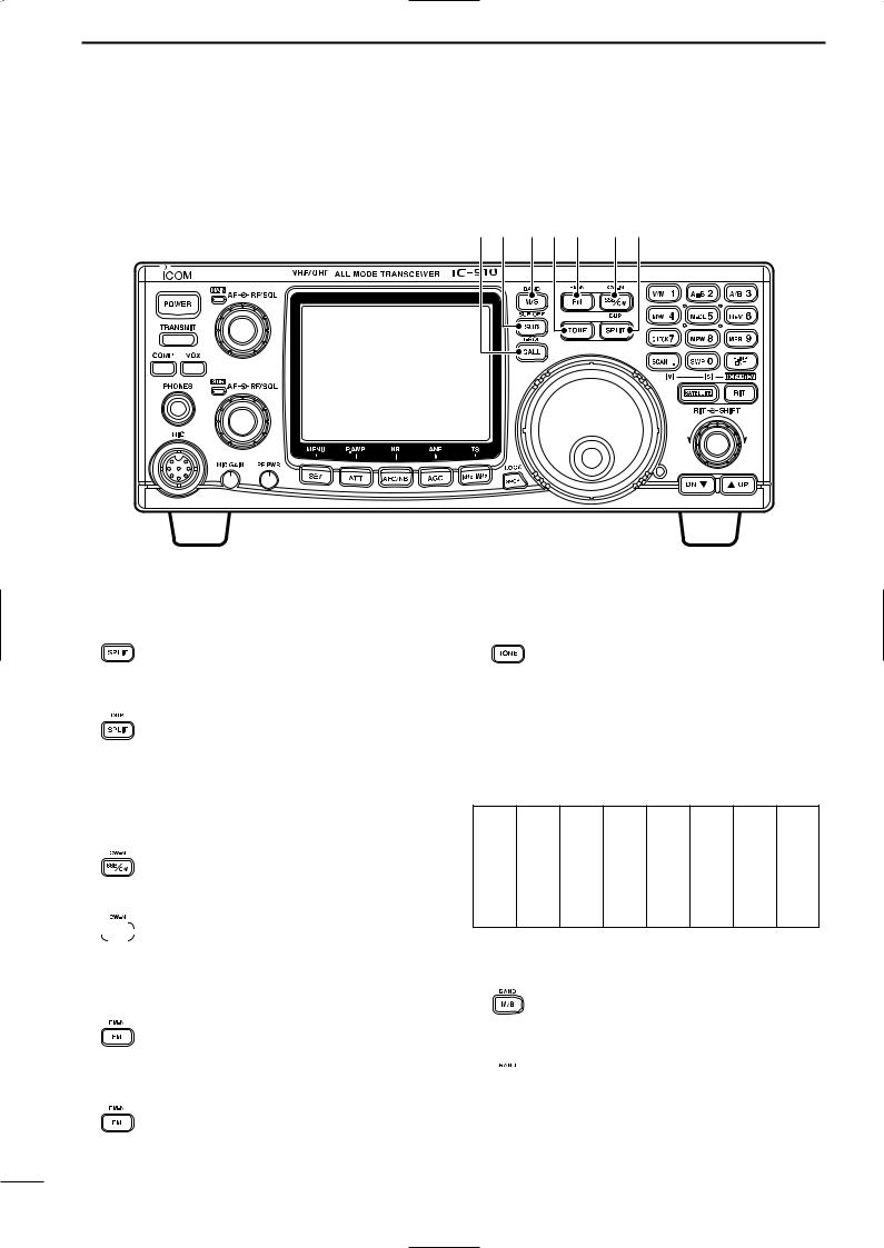
■ Front panel (continued)
#5#4 #3#2#1 #0@9 |
@9SPLIT•DUPLEX SWITCH [SPLIT•DUP]
Push to turn the split function, with the VFO A and B, ON and OFF. (p. 37)
•The split operation is not available for the SUB band.
|
Push for 1 sec. to select the duplex (re- |
|
peater) direction or to turn the function |
For 1 sec. |
OFF. (p. 34) |
•The duplex operation is not available for the SUB band.
#0SSB/CW•CW-NARROW SWITCH [SSB/CW•CW-N]
Push to switch the operating mode between SSB and CW. (p. 23)
Push for 1 sec. to switch the operating
 mode between USB and LSB or between For 1 sec. CW and CW narrow during SSB or CW
mode, respectively.
#1FM•FM-NARROW SWITCH [FM•FM-N] (p. 23)
Push to switch the operating mode between FM and FM repeater mode.
•The duplex operation can be made in MAIN band only, it cannot be operated in SUB band.
Push for 1 sec. to switch the operating
mode between FM and FM-N (FM nar-
For 1 sec. row).
•The FM-N mode cannot be selected in 1200 MHz band operation.
#2TONE SWITCH [TONE] (p. 34)
Push to turn the tone encoder function
ON and OFF in FM mode. (except Europe, Sweden and Italy versions)
•“T” indicator appears in the display when the tone encoder is activated.
Push to transmit a 1750 Hz repeater tone in FM mode for European, Sweden and Italy versions.
Available repeater tones |
(Unit: Hz) |
67.0085.4 107.2 136.5 165.5 186.2 210.7 254.1
69.3088.5 110.9 141.3 167.9 189.9 218.1
71.9091.5 114.8 146.2 171.3 192.8 225.7
74.4094.8 118.8 151.4 173.8 196.6 229.1
77.0097.4 123.0 156.7 177.3 199.5 233.6
79.7100.0 127.3 159.8 179.9 203.5 241.8
82.5103.5 131.8 162.2 183.5 206.5 250.3
#3MAIN/SUB CHANGE•BAND SWITCH [M/S•BAND]
Push to replace the MAIN band’s frequency and mode with the SUB band’s. (p. 19)
Push for 1 sec. to change the operating
 band during single band operation or For 1 sec. when the optional band unit, UX-910, is
installed. (p. 20)
8
PANEL DESCRIPTION 2
#4SUB•SUB OFF SWITCH [SUB•SUB OFF]
Push to enable the SUB band control from the tuning dial, keypad, etc. (p. 19)
• “SUB” indicator appears.
Push for 1 sec. to turn the SUB band readout indication ON and OFF. (p. 24)
For 1 sec.
#5CALL•TONE SQUELCH SWITCH [CALL•T-SQL]
Push to select the call channel of the op-
erating band. The call channel can be selected from both the VFO and memory mode operation. (p. 43)
Push for 1 sec. to turn the tone squelch
function ON and OFF during FM mode operation. (p. 30)
•“T-SQL” indicator appears when the tone squelch is activated.
9
2 PANEL DESCRIPTION
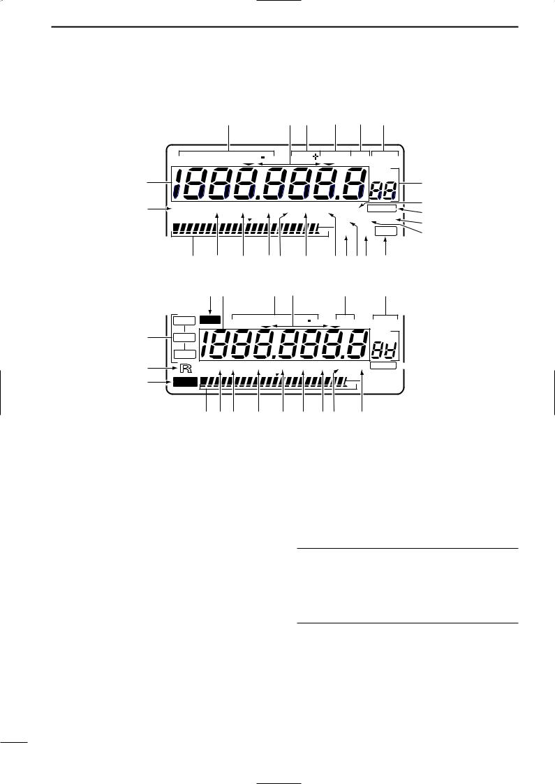
■ Function display
|
|
w |
|
e r |
t |
y |
u |
|
||
|
FMN USBLSB CW N |
DUP |
SPLIT RIT VFO A |
|
||||||
|
|
|
|
|
|
|
|
VFO B |
|
|
|
|
|
|
|
|
|
|
MEMO |
|
|
q |
|
|
|
|
|
|
|
|
i |
|
@4 |
T-SQL ATT P.AMP AFC NB FAGC NR ANF |
B LA N |
o |
|||||||
!0 |
||||||||||
|
S 1 |
3 5 7 9 |
20 |
40 |
60dB SWP COMP 9600 |
|||||
|
!1 |
|||||||||
|
|
|
|
|
|
O V E R |
|
|
||
|
|
|
|
|
|
SCAN VOX SET |
!2 |
|||
|
|
@3 @2 @1 @0!9 !8 |
!7!6!5!4 !3 |
|
||||||
|
|
@5q |
w e |
|
|
y |
u |
|
||
|
NOR SUB |
|
FMN USB LSB C W N |
RIT |
|||||
@6 |
SATL |
|
|
|
|
|
|
|
|
|
REV |
|
|
|
|
|
|
|
|
@7 |
T-SQL ATT P.AMP AFCNB FAGC NR A |
||||||||
S 1 |
3 |
5 |
7 |
9 |
20 |
40 |
60dB |
||
|
|||||||||
@8 |
LOCK |
|
|
|
|
|
|
O V E |
|
|
|
|
|
|
|
|
|||
|
@3@4@2 |
|
@1 |
@0 !9 !8!7 o |
|||||
VFO A
VFO B
MEMO

 i
i
BLANK  !0
!0
SW  !5 SCA
  !6
!6
q FREQUENCY READOUTS (p. 22) Shows the operating frequency.
• Setting item name is indicated during set mode. (p. 55)
w MODE INDICATOR (p. 23)
Shows the selected operation mode.
e TUNING STEP INDICATOR (p. 22)
Appears when the 1 kHz or 1 MHz tuning step is selected.
r DUPLEX INDICATOR (p. 34)
Either “DUP–” or “DUP+” appears during duplex (repeater) operation.
t SPLIT INDICATOR (p. 37)
Appears during split operation.
y RIT INDICATOR (p. 27)
Appears while the RIT function is activated.
Flashes while the SUB dial function is activated.
u VFO INDICATOR (p. 21)
Either VFO A or VFO B appears during VFO operation.
i MEMORY MODE INDICATORS/MEMORY CHANNEL NUMBER READOUTS (p. 40)
The memory mode indicator appears during memory mode operation and the memory channel number readout shows the selected memory channel number during both the memory and VFO mode operation.
Memory channel number readout
In addition to the memory channel number indication, the memory channel number readout indicates 10 Hz and 1 Hz digits of operating frequency while rotating the tuning dial in SSB or CW mode with 10 or 1 Hz tuning step. After 2 sec. from tuning dial operation, the readout indicates the memory channel number.
o AUTO NOTCH FILTER INDICATOR (p. 31) Appears when the optional DSP unit, UT-106, is installed, and the ANF (Automatic Notch Filter) function is activated.
!0BLANK INDICATOR (p. 42)
Appears when the selected memory channel has not been programmed or has been cleared.
10

!1DATA TRANSMISSION SPEED INDICATOR
(p. 52)
Appears when 9600 bps speed is selected for packet transmission.
!2SPEECH COMPRESSOR INDICATOR (p. 36) Appears when the speech compressor is activated.
!3SET INDICATOR (p. 55) Appears when [SET] is pushed.
Disappears after any switch is pushed.
!4VOX INDICATOR (p. 33)
Appears when the VOX function is activated.
!5SWEEP INDICATOR (p. 29)
Flashes while the simple bandscope function is activated.
!6SCAN INDICATOR (p. 46)
Flashes while scanning.
!7NOISE REDUCTION INDICATOR (p. 31)
Appears when the optional DSP unit, UT-106, is installed and the noise reduction is activated.
!8AGC TIME CONSTANT INDICATOR (p. 28) Appears when the FAST AGC time constant is selected; disappears when the SLOW AGC time constant is selected.
!9NOISE BLANKER INDICATOR (p. 30)
Appears when the noise blanker function is activated.
@0AUTO FREQUENCY CONTROL INDICATOR
(p. 28)
Appears when the AFC (Automatic Frequency Control) function is activated.
@1PRE-AMP INDICATOR (p. 16)
Appears when the optional pre-amplifier unit, AG-25, AG-35 and/or AG-1200, is connected and the pre-amplifier function is activated.
@2ATTENUATOR INDICATOR (p. 29)
Appears when the attenuator is activated.
@3MULTI-FUNCTION BAR METER
Shows the receiving signal strength as an S- meter while receiving. Peak hold function is available and can be switched ON and OFF in regular set mode. (pgs. 26, 56)
Shows the relative transmit output power level as an RF power indicator during transmit. (p. 32)
Shows signal availability in the sweeping band, and the “ ” indicator indicates the center of the sweeping frequency band.
PANEL DESCRIPTION 2
@4TONE SQUELCH INDICATOR (pgs. 30, 34)
“T” appears when the tone encoder function is activated; “T-SQL” appears when the tone squelch function is activated.
@5SUB INDICATOR (p. 19)
Appears when the SUB band access is enabled.
@6SATELLITE INDICATOR (p. 49)
Appears while satellite operation mode is selected.
• SATL - NOR : Satellite operation with normal mode is selected.
: Satellite operation with reverse mode is selected.
@7REMOTE INDICATOR (p. 78)
Appears when the transceiver is controlled remotely via the optional CI-V level converter, CT-17.
@8LOCK INDICATOR (p. 25)
Appears when the dial lock function is activated.
11
2 PANEL DESCRIPTION
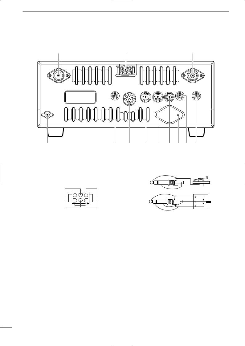
■ Rear panel
q |
w |
e |
!2 |
!1 !0 o i u y t r |
q 430(440) MHz ANTENNA CONNECTOR (p. 15) Accepts a 50 Ω antenna with a type-N connector.
w DC POWER SOCKET [DC 13.8V] (p. 17)
Accepts 13.8 V DC through the supplied DC power cable (OPC-657A).
u KEY JACK [KEY] (p. 15)
Accepts a paddle, a straight key or external electronic keyer with 1⁄8 inch standard plug.
(+)
(_)
Rear panel _ |
+ |
view |
|
e 144 MHz ANTENNA CONNECTOR (p. 15) Accept a 50 Ω antenna with a PL-259 connector.
r SUB BAND EXTERNAL SPEAKER JACK [SP (SUB)]
t MAIN BAND EXTERNAL SPEAKER JACK [SP (MAIN)] (p. 16)
Accepts a 4–8 Ω speaker.
By connecting an external speaker for each or both jacks, the audio for both the MAIN and SUB bands is output as follows.
|
MAIN AF |
SUB AF |
|
|
|
No |
Int. SP |
Int. SP |
|
|
|
SP (MAIN) |
Ext. SP |
Ext. SP |
SP (SUB) |
Int. SP |
Ext. SP |
Both |
Ext. SP (MAIN) |
Ext. SP (SUB) |
|
|
|
y 1200 MHz ANTENNA CONNECTOR (p. 15) Available when the optional 1200 MHz band unit is installed. Accepts a 50 Ω antenna with a type-N connector.
(dot)
(com)
(dash)
i SUB BAND DATA SOCKET [DATA (SUB)] o MAIN BAND DATA SOCKET [DATA (MAIN)]
(p. 13)
6-pin mini plug DIN jack to connect a TNC, etc. for high speed data communications.
Simultaneous data communications are provided by equipping independent data sockets for both MAIN and SUB bands.
!0ACCESSORY SOCKET [ACC(1)]
Enables connection of external equipment such as a TNC for data communications, etc.
• See the right table for socket information.
!1CI-V REMOTE CONTROL JACK [REMOTE]
(p. 78)
Designed for use with a personal computer via the optional CT-17 for remote control of transceiver functions.
!2GROUND TERMINAL [GND] (p 14)
Connect this terminal to a ground to prevent electrical shocks and other problems.
12
PANEL DESCRIPTION 2
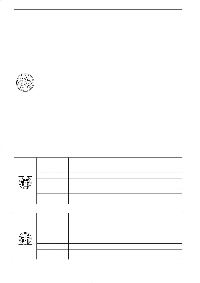
DACC SOCKETS
ACC(1) Socket |
Pin No. |
Pin Name |
Description |
Specification |
|||
|
|
|
|
|
|
|
|
|
|
|
1 |
NC |
No connection. |
|
|
|
|
|
|
|
|
|
|
|
|
|
2 |
GND |
Connect to ground. |
|
|
|
|
|
|
|
|
|
|
|
|
|
|
|
Input terminal to transmit the trans- |
Transmit voltage |
: –0.5 to +0.8 V |
|
|
|
3 |
SEND |
ceiver in relation to the external equip- |
Output current |
: Less than 20 mA |
|
|
|
|
|
ment. (Grounded: transmits) |
Input current (Tx) |
: Less than 200 mA |
|
|
|
|
|
|
|
|
|
|
|
4 |
MOD |
Input terminal for the modulation cir- |
Output impedance |
: 10 kΩ |
|
|
|
|
|
cuit. |
Input level |
: 100 mV rms |
|
2 |
|
|
|
|
|
|
4 |
|
|
|
Output terminal for AF signals from |
Output impedance : 4.7 kΩ |
||
5 |
|
|
|||||
1 |
8 3 |
5 |
AF |
the AF detector circuit. Output level is |
Output level |
: 100–300 mV rms |
|
6 |
7 |
|
|
fixed, regardless of [AF] control. |
|
|
|
|
|
|
|
|
|
|
|
|
|
|
|
|
Output terminal for squelch condition |
Squelch open |
: Less than 0.3 V/5 mA |
|
|
|
6 |
SQLS |
(Open/Close). Outputs grounded level |
Squelch close |
: More than 6.0 V/100 µA |
|
|
|
|
|
signal when squelch is opened. |
|
|
|
|
|
|
|
|
|
|
|
|
|
7 |
13.8 V |
Output terminal for 13.8 V DC, in re- |
Output current |
: Less than 1 A |
|
|
|
|
|
lation to the [POWER]. |
|
|
|
|
|
|
|
|
|
|
|
|
|
8 |
ALC |
Input terminal for ALC control. |
Input impedance |
: More than 10 kΩ |
|
|
|
|
|
|
Control voltage |
: –4 to 0 V |
|
|
|
|
|
|
|
|
DDATA SOCKETS |
|
|
||
oMAIN BAND DATA SOCKET |
|
|||
DATA Socket |
Pin No. |
Pin Name |
Description |
|
|
|
1 |
DATA IN |
Input terminal for data (common for both 1200 and 9600 bps) |
|
|
2 |
GND |
Ground line for the DATA IN, DATA OUT and AF OUT. |
q |
w |
3 |
PTTP |
Transmits when this terminal is grounded. |
e |
r |
4 |
DATA |
Received data output terminal for 9600 bps operation. |
|
|
|
OUT |
|
t |
y |
5 |
AF OUT |
Received data output terminal for 1200 bps operation. |
|
|
|||
|
|
|
|
|
|
|
|
|
6 |
SQL |
Output terminal for squelch condition (Open/Close). Outputs grounded level signal |
|
|
|
|
|
|
|
|
|
|
|
when squelch is opened, +8 V level signal when squelch is closed. |
|
|
|
|
|
|
|
|
|
|
||
iSUB BAND DATA SOCKET |
|
||||||||||
|
|
|
|
|
|
|
|
|
|
|
|
DATA Socket |
Pin No. |
Pin Name |
Description |
||||||||
|
|
|
|
|
|
|
|
|
1 |
DATA IN |
Input terminal for data (common for both 1200 and 9600 bps) |
|
|
|
|
|
|
|
|
|
|
|
|
|
|
|
|
|
|
|
|
|
2 |
GND |
Ground line for the DATA IN, DATA OUT and AF OUT. |
|
|
|
|
|
|
|
|
|
|
|
|
q |
|
|
|
|
|
|
|
w |
3 |
NC |
No connection. |
|
|
|
|
|
|
|
|
|
|
|
|
e |
r |
4 |
DATA |
Received data output terminal for 9600 bps operation. |
|
|
|
OUT |
|
t |
y |
5 |
AF OUT |
Received data output terminal for 1200 bps operation. |
|
|
6 |
SQL |
Output terminal for squelch condition (Open/Close). Outputs grounded level signal |
|
|
when squelch is opened, +8 V level signal when squelch is closed. |
13
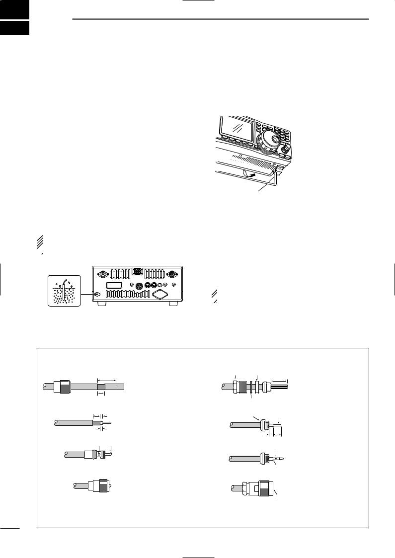
3 INSTALLATION AND CONNECTIONS
■ Unpacking |
■ Selecting a location |
After unpacking, immediately report any damage to the delivering carrier or dealer. Keep the shipping cartons.
For a description and a diagram of accessory equipment included with the IC-910H, see ‘Supplied accessories’ on p. 1 of this manual.
■ Grounding
To prevent electrical shock, television interference (TVI), broadcast interference (BCI) and other problems, ground the transceiver through the GROUND terminal on the rear panel.
For best results, connect a heavy gauge wire or strap to a long earth-sunk copper rod. Make the distance between the [GND] terminal and ground as short as possible.
 RWARNING: NEVER connect the [GND]
terminal to a gas or electric pipe, since the connec-  tion could cause an explosion or electric shock.
Select a location for the transceiver that allows adequate air circulation, free from extreme heat, cold, or vibrations, and away from TV sets, TV antenna elements, radios and other electro-magnetic sources.
The base of the transceiver has an adjustable stand for desktop use. Set the stand to depending on your operating conditions.
■ Antenna connection
For radio communications, the antenna is of critical importance, along with output power and sensitivity. Select antenna(s), such as a well-matched 50 Ω antenna, and feedline. 1.5:1 or better of Voltage Standing Wave Ratio (VSWR) is recommended for your desired band. Of course, the transmission line should be a coaxial cable.
 CAUTION: Protect your transceiver from lightning
  by using a lightning arrestor.
PL-259 CONNECTOR INSTALLATION EXAMPLE
q
w
e
r
30 mm
Coupling ring 10 mm (soft solder)
10 mm
Soft solder
1–2 mm
solder solder
Slide the coupling ring down. Strip the cable jacket and soft solder.
Strip the cable as shown at left. Soft solder the center conductor.
Slide the connector body on and solder it.
Screw the coupling ring onto the connector body.
TYPE-N CONNECTOR INSTALLATION EXAMPLE
q |
Nut |
Rubber gasket |
Slide the nut, rubber |
|
|
|
15 mm |
||
|
|
|
||
|
|
|
|
gasket and clamp over the |
|
|
|
|
coaxial cable, then cut the |
|
|
Washer |
|
end of the cable evenly. |
|
|
|
|
|
w |
|
Clamp |
Center |
|
|
|
conductor |
|
|
|
|
|
|
Strip the cable and fold the |
|
|
|
|
braid back over the clamp. |
|
|
3 mm |
6 mm |
|
|
|
|
|
|
e |
Solder hole |
|
No space |
r
Be sure the center conductor is the same height as the plug body.
Soft solder the center conductor. Install the center conductor pin and solder it.
Carefully slide the plug body into place aligning the center conductor pin on the cable. Tighten the nut onto the plug body.
30 mm ≈ 9⁄8 in 10 mm ≈ 3⁄8 in 1–2 mm ≈ 1⁄16 in
14

INSTALLATION AND CONNECTIONS 3
■ Required connections
• Front panel
HEADPHONES
Input impedance: 8–16 Ω
Audio output power:
5 mW with 8 Ω load Output power may differ
according to the headphone
HM-12 HAND |
SM-20 DESKTOP |
MICROPHONE CONNECTOR (Front panel view) |
||
MICROPHONE |
MICROPHONE (optional) |
|
q MIC (Microphone input) |
|
|
|
|
|
|
|
|
i |
|
w +8V (Max. 8 V DC 10 mA) |
|
|
q |
u |
e MIC U/D (Frequency up/down) |
|
|
w |
y |
r SQL S (Squelch switch) |
|
|
t PTT |
||
|
|
e |
t |
|
|
|
y GND (PTT ground) |
||
|
|
r |
|
|
|
|
|
u GND (Microphone ground) |
|
|
|
|
|
|
|
|
|
|
i AF OUT (varies with [AF]) |
|
|
CAUTION: DO NOT short pin 2 to ground as this can damage the |
||
|
|
internal 8 V regulator. DC voltage is applied to pin 1 for microphone |
||
|
|
operation. Take care when using a non-Icom microphone. |
||
• Rear panel
[430(440)MHz ANT]
(p. 14)
DC POWER SUPPLY (p. 17) |
[144MHz ANT] (p. 14) |
_ |
+ |
|
13.8 V DC |
More than 25 A
GROUND (p. 14) |
[1200MHz ANT] (p. 14) |
[KEY] jack (p. 38) |
+
_
(dot)
(com)
(dash)
Required for optional
UX-910 operation.
15
3 INSTALLATION AND CONNECTIONS
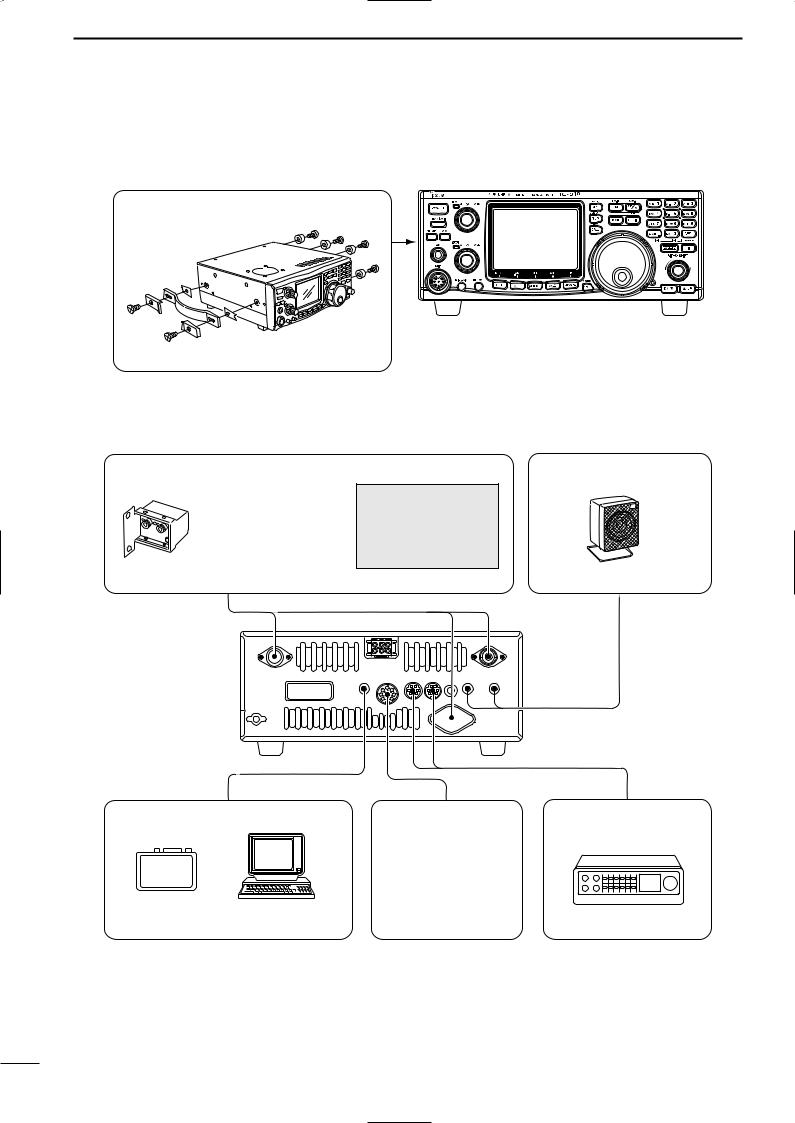
■ Advanced connections
• Front panel
MB-23 CARRYING HANDLE
• Rear panel
PREAMP (p. 59)
(144 MHz/430(440) MHz/1200 MHz)
144 MHz |
: AG-25 |
430(440) MHz : AG-35 |
|
1200 MHz |
: AG-1200 |
External all-weather, mast mounting preamplifiers are available.
EXTERNAL SPEAKER (MAIN/SUB) (p. 12)
CAUTION: NEVER
icom sp-7
connect equipment
(i.e. power, SWR meter) between transceiver and preamplifier.
Use 4–8 Ω speakers.
430(440) MHz |
1200 MHz (optional) |
144 MHz |
MAIN SUB
MAIN SUB
[REMOTE] (p. 78)
CT-17
Used for computer control and transceive operation.
ACC SOCKETS |
DATA SOCKETS |
(pgs. 13, 52) |
(MAIN/SUB) (pgs. 13, 52) |
Used for external equipment control.
16
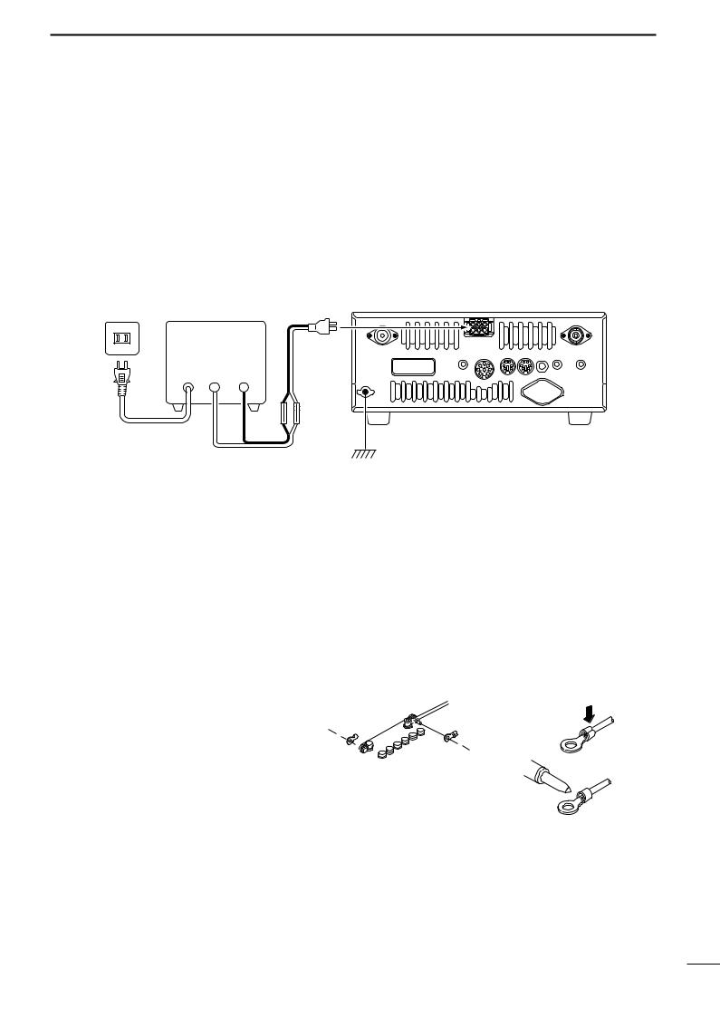
■ Power supply connections
Use an optional DC power supply with a 25 A capacity and above when operating the transceiver with AC power. Refer to the diagrams below.
CONNECTING A DC POWER SUPPLY
|
Supplied DC |
AC outlet |
A DC power supply power cable |
|
13.8 V DC 25 A |
|
Black Red |
|
_ + |
AC cable
INSTALLATION AND CONNECTIONS 3
CAUTION: Before connecting the DC power cable, check the following important items. Make sure:
•The [POWER] switch is OFF.
•Output voltage of the power source is 12–15 V when you use a non-Icom power supply.
•DC power cable polarity is correct.
Red |
: positive + terminal |
Black |
: negative _ terminal |
IC-910H
CONNECTING A VEHICLE BATTERY
24V |
NEVER connect to |
|
a 24 V battery. |
||
|
|
NEVER use the cig- |
Ciga |
arette lighter socket as |
a power source. |
IC-910H |
NOTE: Use terminals for |
|
the cable connections. |
+ red |
Crimp |
_ black |
|
Grommet |
|
12 V |
Solder |
|
|
battery |
|
Supplied |
|
DC power cable |
|
17

4 BASIC OPERATION
■ Initial settings
After resetting the transceiver, set controls and |
CCW : Max. counterclockwise |
|
switches as shown in the figure below. |
|
|
|
[AF] (MAIN band): |
|
|
CCW |
|
[POWER]: OFF |
[RF/SQL] (MAIN band): |
[SATELLITE]: OFF |
12 o’clock |
||
[TRANSMIT]: OFF |
|
[COMP]: OFF |
|
[VOX]: OFF |
[RIT]: OFF |
|
|
[AF] (SUB band): |
[SHIFT]: 12 o’clock |
CCW |
[RF/SQL]: (SUB band) |
|
[AGC]: OFF |
|
|
12 o’clock |
[SET]: OFF |
[AFC/NB]: OFF |
[RIT]: 12 o’clock |
|
[MIC]: CCW |
||||
[ATT(P.AMP)]: OFF |
|
|||
|
|
|||
|
[RF PWR]: CCW |
|
|
|
Turn power ON, then check the display. If any of the following indicators appear, turn them OFF as follows:
• Quick tuning step indicator “▼” : Push [kHz/MHz].
• RIT indicator “RIT” |
: Push [RIT]. |
• Split indicator “SPLIT” |
: Push [SPLIT]. |
■ When first applying power (CPU resetting)
Before first applying power, make sure all connections required for your system are complete by referring to Chapter 3. Then, reset the transceiver using the following procedure.
q Make sure the transceiver power is OFF.
wWhile pushing [MW 4] and [M-CL 5], push [POWER] to turn power ON.
•The internal CPU is reset.
•The transceiver displays its initial VFO frequencies when resetting is complete.
|
FM |
|
|
|
|
|
|
|
VFO A |
|
S |
1 |
3 |
5 |
7 |
9 |
|
20 |
40 |
60dB |
|
|
|
|
|
|
FM |
|
|
|
|
VFO A |
|
|
S |
1 |
3 |
5 |
7 |
9 |
20 |
40 |
60dB |
[POWER] |
[MW 4] [M-CL 5] |
 Resetting CLEARS all programmed contents in
  memory channels and returns programmed values
  in set mode to default values.
18
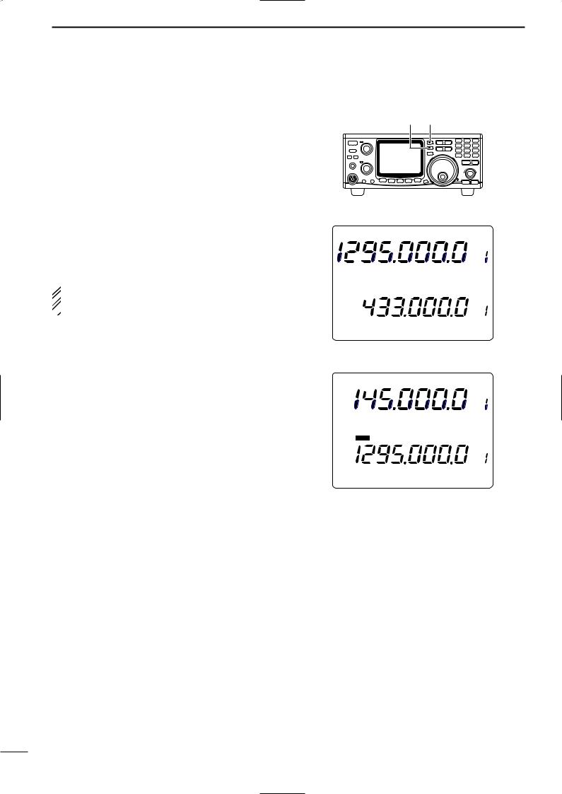
■ MAIN and SUB bands
The IC-910H has dual bands: 144 MHz and 430(440) MHz. These bands can be assigned to the MAIN and SUB bands for operating convenience.
Each MAIN and SUB bands have independent features.
The MAIN band is the operation for both transmit and receive, and is displayed in the upper area of the function display. The SUB band is the operation for only receive, and is displayed in the lower area of the function display.
 Simultaneous receive on both the MAIN and SUB
bands is possible, however the transmission can
 only be transmitted on the MAIN band— not on the
SUB band.
 In the case of satellite operation mode, the SUB
  band is used for the transmission band.
DExchanging the MAIN and SUB bands
The function display shows both the MAIN and SUB band frequencies and both bands can receive signals simultaneously.
MAIN band display
|
FM |
|
|
|
|
|
|
|
VFO A |
|
S |
1 |
3 |
5 |
7 |
9 |
|
20 |
40 |
60dB |
|
|
|
|
|
|
FM |
|
|
|
|
VFO A |
|
|
S |
1 |
3 |
5 |
7 |
9 |
20 |
40 |
60dB |
SUB band display
DAccessing the SUB band
Normally, any operations, such as tuning, operating mode selection, memory channel selection and programming, etc., are performed on the MAIN band. However, these operations can be performed on the SUB band by using the SUB band access capability.
|
FM |
|
|
|
|
|
|
|
VFO A |
|
S |
1 |
3 |
5 |
7 |
9 |
|
20 |
40 |
60dB |
|
|
|
|
|
|
FM |
|
|
|
|
VFO A |
|
|
S |
1 |
3 |
5 |
7 |
9 |
20 |
40 |
60dB |
BASIC OPERATION 4
MAIN band display
FM |
|
|
|
|
|
|
|
VFO A |
|
S 1 |
3 |
5 |
7 |
9 |
|
20 |
40 |
60dB |
|
|
|
|
|
FM |
|
|
|
|
VFO A |
|
S |
1 |
3 |
5 |
7 |
9 |
20 |
40 |
60dB |
|
|
|
|
SUB band display |
|||||
Assign 144 MHz or 430(440) MHz band, whichever band you want to transmit or be called on, as the MAIN band.
Push [M/S] to exchange the MAIN and SUB bands.
|
FM |
|
|
|
|
|
|
|
VFO A |
|
S |
1 |
3 |
5 |
7 |
9 |
|
20 |
40 |
60dB |
|
|
|
|
|
|
FM |
|
|
|
|
VFO A |
|
|
S |
1 |
3 |
5 |
7 |
9 |
20 |
40 |
60dB |
Push [SUB] to switch the SUB band access capability ON and OFF.
•“SUB” indicator appears while the SUB band access capability is activated.
•Even during SUB band access, transmission cannot be made on the SUB band.
|
FM |
|
|
|
|
|
|
|
VFO A |
|
S |
1 |
3 |
5 |
7 |
9 |
|
20 |
40 |
60dB |
|
|
|
SUB |
|
FM |
|
|
|
|
VFO A |
|
|
|
S |
1 |
3 |
5 |
7 |
9 |
20 |
40 |
60dB |
19
4 BASIC OPERATION
■ Operating band selection (optional UX-910 is required)
The IC-910H can be used on the additional 1200 MHz
[SUB] [M/S•BAND]
band with the optional UX-910. The operating band can be selected by pushing [M/S•BAND] for 1 sec.
DSelecting on the MAIN band
qPush [SUB] to cancel the SUB band access, if required.
wPush [M/S•BAND] for 1 sec. to select operating band.
Select 1200 MHz to MAIN band.
FM |
|
|
|
|
|
VFO A |
|
S 1 |
3 |
5 |
7 |
9 |
20 |
40 |
60dB |
 NOTE: The same operating band cannot be as-
  signed on both MAIN and SUB bands, simultane-
  ously.
DSelecting on the SUB band
qPush [SUB] to enable the SUB band access.
• “SUB” indicator appears.
wPush [M/S•BAND] for 1 sec. to select operating band.
|
|
|
|
|
|
|
|
|
VFO A |
|
S |
1 |
3 |
5 |
7 |
9 |
20 |
40 |
60dB |
Select 1200 MHz to SUB band. |
|||||||||
FM |
|
|
|
|
|
|
|
VFO A |
|
S 1 |
3 |
5 |
7 |
9 |
|
20 |
40 |
60dB |
|
SUB |
|
FM |
|
|
|
|
VFO A |
|
S |
1 |
3 |
5 |
7 |
9 |
20 |
40 |
60dB |
20
■ VFO description
The IC-910H has two VFOs for both bands, specially suited for instant selection of 2 frequencies or split frequency operation. The VFOs are called VFO A and VFO B. You can use the desired VFO to call up a frequency and operating mode for your operation.
VFO is an abbreviation of Variable Frequency Oscillator, and traditionally refers to an oscillator.
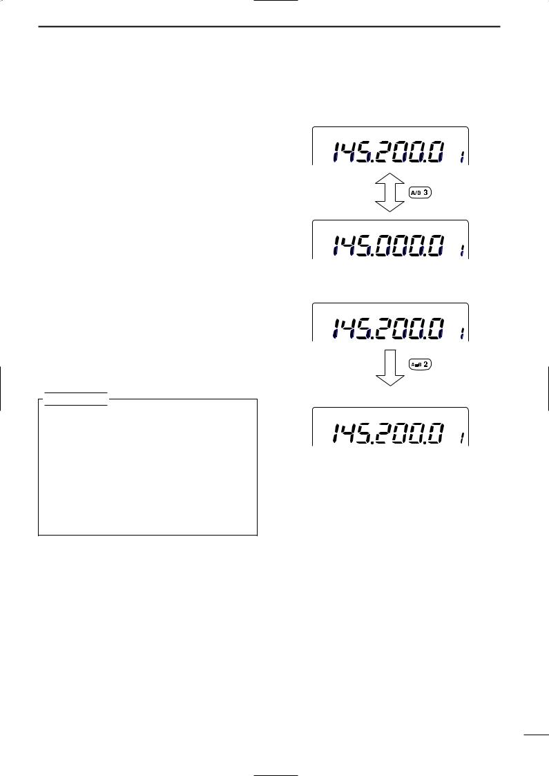
DSelecting the VFO A/B
Push [A/B 3] to switch between the VFO A and VFO B.
DVFO equalization
Push [A=B 2] for 1 sec. to equalize the undisplayed VFO condition to the displayed VFO.
•3 beeps sound when the VFO equalization is completed.
CONVENIENT
Use two VFOs as a quick memory
When you find a new station, but you wish to continue searching, the two VFO system can be used for quick memory storage.
qPush [A=B 2] for 1 sec. to store the displayed frequency into the undisplayed VFO.
w Continue searching for stations.
e Push [A/B 3] to retrieve the stored frequency.
rTo continue searching for stations, push [A/B 3] again.
BASIC OPERATION 4
VFO selection
FM |
VFO A |
FM
VFO B
displayed VFO
FM |
VFO A |
undisplayed VFO
FM
VFO B
Equalizes the undisplayed VFO condition to the displayed VFO.
21
4 BASIC OPERATION
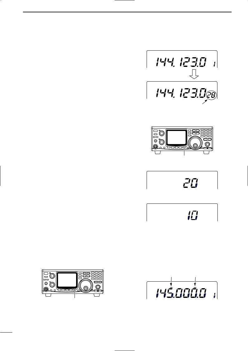
■ Frequency setting
The IC-910H has several tuning steps and a [kHz/MHz] switch for convenient frequency tuning.
qPush [M/S] to select the desired frequency band as the MAIN band; or push [SUB] to access the SUB band.
wRotate the tuning dial to select the frequency.
•The memory channel number changes to the 10 and 1 Hz digits when rotating the tuning dial with 1, 10, 100 Hz and 6.25 kHz tuning steps.
•When you want to check the 10 and 1 Hz digits during memory channel number indication, push and hold [A/B] (10 and 1 Hz digits are indicated while holding).
DTuning step selection
Tuning steps can be pre-set independently for FM and SSB/CW. The following steps are selectable.
• FM : 0.1, 5, 6.25, 10, 12.5, 20, 25 or 100 kHz
• SSB/CW : 1, 10, 50 or 100 Hz
qPush [M/S] to select the desired frequency band as the MAIN band; or push [SUB] to access the SUB band.
wPush [FM] or [SSB/CW] to select the desired operation mode.
ePush [kHz/MHz•TS] for 1 sec. to enter the tuning step set mode.
rRotate the tuning dial to select the desired tuning step.
t Push [kHz/MHz•TS] to return to previous display.
DQuick tuning step
The operating frequency can be changed in 1 kHz steps or 1 MHz steps for quick tuning.
Push [kHz/MHz•TS] to switch the quick tuning step in sequence 1 kHz, 1 MHz and OFF.
[kHz/MHz•TS]
USB |
VFO A |
While tuning
USB
10 Hz/1 Hz indication
[kHz/MHz•TS] for 1 sec.
FM mode tuning step set mode
FM
(20 kHz tuning step)
SSB/CW mode tuning step set mode
USB
(10 Hz tuning step)
1 MHz tuning step |
1 kHz tuning step |
FM |
VFO A |
22
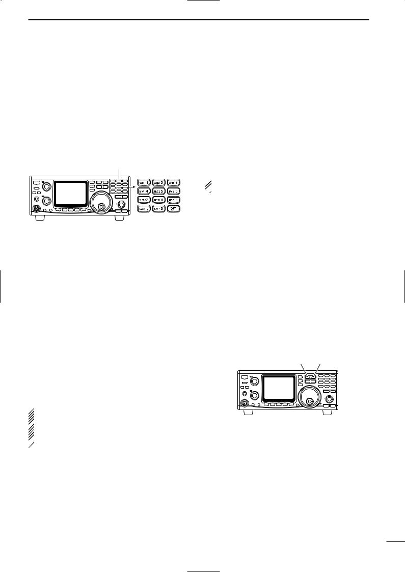
DFrequency setting with the keypad
The operating frequency can be directly entered from the keypad.
q Push [F-INP ENT] to access the keypad frequency entry.
• All digits of frequency indication disappear.
wPush numeral keys to enter the desired operating frequency.
•The entered number is indicated from the 100 Hz digit. e Push [F-INP ENT] to set the frequency.
keypad
BASIC OPERATION 4
[EXAMPLE]
145.3400 MHz
[F-INP ENT] [1] [4] [5] [.] [3] [4] [F-INP]
435.0000 MHz
[F-INP ENT] [4] [3] [5] [.] [F-INP ENT]
439.1200 MHz
[F-INP ENT] [4] [3] [9] [.] [1] [2] [F-INP ENT]
439.1200 MHz to 439.2604 MHz
[F-INP ENT] [.] [2] [6] [0] [4] [F-INP ENT]
 Pushing numeral keys to 100 Hz digit without push-
  ing [.] also sets the desired operating frequency.
DOperating mode selection
SSB (USB/LSB), CW, CW-N (CW narrow), FM and FM-N (FM narrow) modes are available in the IC-910H. Select the desired operation mode as follows.
• Selecting SSB mode
Push [SSB/CW] to select USB mode.
•USB mode is generally used for SSB phone operation on the VHF and UHF bands.
•Push [SSB/CW] for 1 sec. after USB mode selection to switch between USB and LSB mode.
• Selecting CW mode
Push [SSB/CW] to select CW mode.
•Push [SSB/CW] for 1 sec. after CW mode selection to switch between CW and CW narrow mode.
 The optional CW narrow filter, FL-132 or FL-133, is
required for the MAIN or SUB bands, respectively.
 In satellite operation, the optional FL-133 is neces-
sary to operate CW narrow mode in the MAIN (re-
 ceive) band. No audio is output until the optional
  CW narrow filter is installed in the CW narrow mode.
• Selecting FM mode
Push [FM] to select FM mode.
•Push [FM] after FM mode selection to turn the repeater mode (duplex negative with repeater tone ON) ON and OFF.
•Push [FM] for 1 sec. after FM mode selection to switch between FM and FM narrow mode.
•When the optional UT-102 voice synthesizer unit is installed.
The UT-102 announces the selected mode in an elec- tronically-generated voice when [SSB/CW] or [FM] is pushed. (pgs. 69, 71)
[FM] [SSB/CW]
23
4 BASIC OPERATION
■ SUB band OFF
The SUB band indication can be deactivated to simplify operation.
Push [SUB•SUB OFF] for 1 sec. to turn the SUB band indication ON and OFF.
•Push [M/S•BAND] for 1 sec. to change the operating band. (p. 20)
[SUB•SUB OFF] for 1 sec.
FM |
|
|
|
|
|
VFO A |
|
S 1 |
3 |
5 |
7 |
9 |
20 |
40 |
60dB |
SUB band indication OFF.
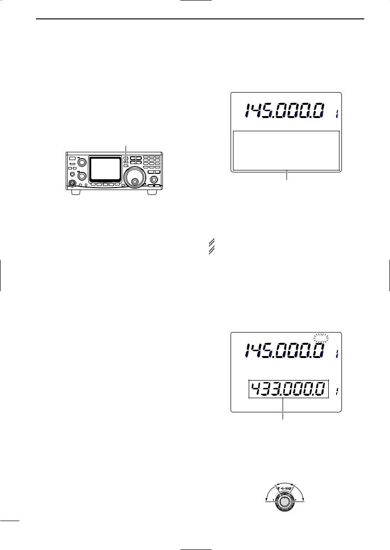
■ SUB tuning dial
The IC-910H has a large main tuning dial for frequency setting. In addition, the [RIT] or [SHIFT] controls can be used as a SUB tuning dial for dual band simultaneous tuning, etc. The SUB tuning dial changes the operating frequency continuously at a variable speed.
To use the SUB tuning dial function, assign the function to either the [RIT] or [SHIFT] control using the RIT/SHIFT set mode.
DWhen the [RIT] control is assigned as SUB tuning dial
qPush [RIT] for 1 sec.
•“RIT” indicator flashes when the SUB tuning dial function is activated.
w Rotate [RIT] control for the desired tuning direction and speed.
• Tuning speed can be adjusted in ±5 steps.
eSet [RIT] control to the center position to stops tuning.
•A beep tone sounds when [RIT] control is set to the center.
r Push [RIT] to cancel the SUB tuning dial function.
 The assigned control can be used for its original
  function, however, both functions cannot be used si-
  multaneously.
FM |
|
|
|
|
|
RIT V F O A |
|
S 1 |
3 |
5 |
7 |
9 |
20 |
40 |
60dB |
|
|
|
FM |
|
|
|
|
V F O A |
S |
1 |
3 |
5 |
7 |
9 |
20 |
40 |
60dB |
While [RIT] is flashing, SUB band can be controlled with sub dial function.
|
SUB dial |
|
Reverses the |
functions |
Advances the |
slightly. |
||
frequency and |
|
frequency and |
increases the |
|
increases the |
speed. |
|
speed. |
24

BASIC OPERATION 4
DSUB tuning dial assignment
q Push [SET] then [RIT] to enter the RIT/SHIFT set
mode. |
|
|
w Push [DN ▼] or [▲ UP] to select [RIT] or [SHIFT] |
[RIT] |
|
control to be assigned. |
||
[SHIFT] |
||
• “rit nob” or “SFt nob” appears. |
||
[RIT] |
||
e Rotate the tuning dial to select the condition as de- |
||
|
||
scribed below. |
|
• Pushing [M-CL 5] for 1 sec. selects the default setting. |
[SET] |
[DN ▼] [▲ UP] |
|
|
r Push [SET] to exit from the RIT/SHIFT set mode.
The [RIT] control functions as [RIT] even when the SUB tuning dial function is in use. (default)
The [RIT] control can be used for MAIN band tuning.
The [RIT] control can be used for SUB band tuning.
The [RIT] control can be used for SUB band IF shift control.
The [SHIFT] control functions as [SHIFT] even when the SUB tuning dial function is in use. (default)
The [SHIFT] control can be used for SUB band IF shift control.
The [SHIFT] control can be used for MAIN band tuning.
The [SHIFT] control can be used for SUB band tuning.
■ Dial lock function
The dial lock function prevents accidental changes caused by the tuning dial (including the SUB tuning dial function).
Push [SPCH•LOCK] for 1 sec. to turn the dial lock function ON and OFF.
•“LOCK” indicator appears while the dial lock function is activated.
[SPCH•LOCK] for 1 sec.
|
FM |
|
|
|
|
|
|
|
VFO A |
|
S |
1 |
3 |
5 |
7 |
9 |
|
20 |
40 |
60dB |
|
|
|
|
|
|
FM |
|
|
|
|
VFO A |
|
|
S |
1 |
3 |
5 |
7 |
9 |
20 |
40 |
60dB |
L |
|
K |
|
|
|
|
|
|
|
|
LOCK indicatior
25
 Loading...