


IC-746

INSTR UCTION MANUAL
VHF/HF ALL MODE TRANSCEIVER
i746
This device complies with Part 15 of the FCC rules. Operation is subject to the following two conditions: (1) This device may not cause
harmful interference, and (2) this device must accept any interference
received, including interference that may cause undesired operation.
The IC-746’s which display the “CE” symbol, comply
with the essential requirements of the 89/336/EEC directive for Electromagnetic Compatibility. This compliance is based on conformity with the ETSI specification
prETS300 684 (EMC product standard for Commercially Available Amateur Radio Equipment).
ii
IMPORTANT
WORD DEFINITION
RWARNING
Personal injury, fire hazard or electric
shock may occur.
CAUTION
Equipment damage may occur.
NOTE
If disregarded, inconvenience only. No risk
of personal injury, fire or electric shock.
READ THIS INSTRUCTION MANUAL CAREFULLY
before attempting to operate the transceiver.
SAVE THIS INSTRUCTION MANUAL—This manual
contains important safety and operating instructions for
the IC-746.
PRECAUTIONS
RWARNING! HIGH VOLTAGE! NEVER attach an
antenna or internal antenna connector during transmission.This may result in an electric shock or burn.
RNEVER apply AC to the [DC13.8V] socket on the
transceiver rear panel.This could cause a fire or ruin
the transceiver.
RNEVER apply more than 16 V DC, such as a 24 V
battery , to the [DC13.8V] soc ket on the transceiver rear
panel.This could cause a fire or ruin the transceiver.
RNEVER let metal, wire or other objects touch any in-
ternal part or connectors on the rear panel of the transceiver. This may result in an electric shock.
NEVER allow children to play with equipment containing a radio transmitter.
NEVER expose the transceiver to rain, snow or any liquids.
AVOID using or placing the transceiver in areas with
temperatures below –10°C (+14°F) or above +60°C
(+140°F). Be aware that temperatures on a vehicle’s
dashboard can exceed 80°C (+176°F), resulting in permanent damage to the transceiver if left there for extended periods.
AVOID placing the transceiver in excessively dusty environments or in direct sunlight.
AVOID placing the transceiver against walls or putting
anything on top of the transceiver. This will obstr uct
heat dissipation.
During mobile operation, DO NOT operate the transceiver without running the vehicle’s engine. When
transceiver power is ON and your vehicle’s engine is
OFF, the vehicle’s battery will soon become exhausted.
Make sure the transceiver power is OFF before starting the vehicle.This will avoid possible damage to the
transceiver by ignition voltage spikes.
During maritime mobile operation, keep the transceiver
and microphone as far away as possible from the magnetic navigation compass to prev ent erroneous indications.
BE CAREFUL! The heatsink will become hot when operating the transceiver continuously for long periods.
BE CAREFUL! If a linear amplifier is connected, set
the transceiver’s RF output power to less than the linear amplifier’s maximum input level, otherwise, the linear amplifier will be damaged.
Use Icom microphones only (supplied or optional).
Other manufacturer’s microphones have different pin
assignments and connection to the IC-746 may damage the transceiver.
EXPLICIT DEFINITIONS
The explicit definitions described below apply to this instruction manual.
BUILT-IN DSP
The IC-746’s DSP digitally transposes receive audio
components in all modes of operation to produce desired AF frequency characteristics at the IF stage of
the transceiver. DSP provides the following functions:
➩ Noise reduction—reduces various types of noise
and enhances receive signal components only.
➩
Automatic notch filter—automatically reduces single
beat interference and protects the receive v oice signals.
➩ Selectable APF—a total of 3 passband widths are
selectable (80/160/320 Hz), for super-narrow filter
APF functions in CW mode. The APF center frequency is adjustable.
DSP

iii
TABLE OF CONTENTS
IMPORTANT . . . . . . . . . . . . . . . . . . . . . . . . . . . . . . ii
PRECAUTIONS . . . . . . . . . . . . . . . . . . . . . . . . . . . . ii
EXPLICIT DEFINITIONS . . . . . . . . . . . . . . . . . . . . . ii
BUILT-IN DSP . . . . . . . . . . . . . . . . . . . . . . . . . . . . . ii
TABLE OF CONTENTS . . . . . . . . . . . . . . . . . . . . . iii
1 PANEL DESCRIPTION . . . . . . . . . . . . . . . . . . 2–7
1-1 Front panel . . . . . . . . . . . . . . . . . . . . . . . . . . . 2
1-2 Rear panel . . . . . . . . . . . . . . . . . . . . . . . . . . . 6
1-3 Function display . . . . . . . . . . . . . . . . . . . . . . . 7
2 MENU SELECTION . . . . . . . . . . . . . . . . . . . . . 8–9
2-1 Menu set 1 flow chart . . . . . . . . . . . . . . . . . . . 8
2-2 Menu set 2 flow chart . . . . . . . . . . . . . . . . . . . 9
3 BASIC OPERATION . . . . . . . . . . . . . . . . . . 10–17
3-1 Before operating . . . . . . . . . . . . . . . . . . . . . . 10
3-2 Squelch and receive (RF) sensitivity . . . . . . 12
3-3 Selecting VFO/memory mode . . . . . . . . . . . 13
3-4 Toggling between VFO A/B and transferring
contents . . . . . . . . . . . . . . . . . . . . . . . . . . . . 13
3-5 Setting a band and frequency . . . . . . . . . . . 14
3-6 Selecting an operating mode . . . . . . . . . . . . 17
4 USING DIFFERENT OPERATING MODES . 18–36
4-1 Operating SSB . . . . . . . . . . . . . . . . . . . . . . . 18
4-2 Operating CW . . . . . . . . . . . . . . . . . . . . . . . . 20
4-3 Operating RTTY (FSK) . . . . . . . . . . . . . . . . . 28
4-4 Operating AM . . . . . . . . . . . . . . . . . . . . . . . . 30
4-5 Operating FM . . . . . . . . . . . . . . . . . . . . . . . . 32
4-6 Repeater operation . . . . . . . . . . . . . . . . . . . 34
4-7 Packet operation . . . . . . . . . . . . . . . . . . . . . . 36
5 FUNCTIONS FOR RECEIVE . . . . . . . . . . . . 37–42
5-1 Simple band scope . . . . . . . . . . . . . . . . . . . . 37
5-2 Preamp and attenuator . . . . . . . . . . . . . . . . 38
5-3 RIT function . . . . . . . . . . . . . . . . . . . . . . . . . 38
5-4 AGC function . . . . . . . . . . . . . . . . . . . . . . . . 39
5-5 1/4 function . . . . . . . . . . . . . . . . . . . . . . . . . . 39
5-6 NB function . . . . . . . . . . . . . . . . . . . . . . . . . . 39
5-7 Noise reduction . . . . . . . . . . . . . . . . . . . . . . 40
5-8 Auto notch (ANF) function . . . . . . . . . . . . . . 40
5-9 Dial lock function . . . . . . . . . . . . . . . . . . . . . 40
5-10 Twin PBT . . . . . . . . . . . . . . . . . . . . . . . . . . 41
5-11 Selecting IF filters . . . . . . . . . . . . . . . . . . . . 42
6 FUNCTIONS FOR TRANSMIT . . . . . . . . . . . 43–48
6-1 VOX function . . . . . . . . . . . . . . . . . . . . . . . . . 43
6-2 Break-in function . . . . . . . . . . . . . . . . . . . . . 44
6-3 :TX function . . . . . . . . . . . . . . . . . . . . . . . . 45
6-4 Monitor function . . . . . . . . . . . . . . . . . . . . . . 45
6-5 Speech compressor . . . . . . . . . . . . . . . . . . . 46
6-6 Split frequency operation . . . . . . . . . . . . . . . 47
6-7 Quick split function . . . . . . . . . . . . . . . . . . . . 48
7 MEMORY CHANNELS . . . . . . . . . . . . . . . . 49–54
7-1 General . . . . . . . . . . . . . . . . . . . . . . . . . . . . . 49
7-2 Memory channel selection . . . . . . . . . . . . . . 49
7-3 Transferring a memory to VFO . . . . . . . . . . . 50
7-4 Clearing a memory . . . . . . . . . . . . . . . . . . . . 50
7-5 Selecting the call channel . . . . . . . . . . . . . . 51
7-6 Programming a memory . . . . . . . . . . . . . . . . 51
7-7 Programming the call channel . . . . . . . . . . . 52
7-8 Programming scan edges . . . . . . . . . . . . . . 52
7-9 Assigning memory names . . . . . . . . . . . . . . 53
7-10 Memo pads . . . . . . . . . . . . . . . . . . . . . . . . 54
8 SCAN OPERATION . . . . . . . . . . . . . . . . . . . 55–58
8-1 Scan types . . . . . . . . . . . . . . . . . . . . . . . . . . 55
8-2 Programmed scan and
fine programmed scan . . . . . . . . . . . . . . . . . 56
8-3 Memory scan . . . . . . . . . . . . . . . . . . . . . . . . 57
8-4 Select memory scan . . . . . . . . . . . . . . . . . . . 57
8-5 :F scan and fine :F scan . . . . . . . . . . . . . . 58
9 INTERNAL ANTENNA TUNER . . . . . . . . . . . . . 59
9-1 Before operating . . . . . . . . . . . . . . . . . . . . . . 59
9-2 Tuner operation. . . . . . . . . . . . . . . . . . . . . . . 59
10 SET MODE . . . . . . . . . . . . . . . . . . . . . . . . . 60–64
10-1 Selecting set mode . . . . . . . . . . . . . . . . . . . 60
10-2 Set mode items . . . . . . . . . . . . . . . . . . . . . 60
11 ADJUSTMENTS . . . . . . . . . . . . . . . . . . . . . 65–66
11-1 Tuning dial brake . . . . . . . . . . . . . . . . . . . . 65
11-2 Frequency calibration . . . . . . . . . . . . . . . . . 65
11-3 Measuring SWR . . . . . . . . . . . . . . . . . . . . . 66
11-4 Adjusting the LCD . . . . . . . . . . . . . . . . . . . 66
12 SETUP AND CONNECTIONS . . . . . . . . . . 67–75
12-1 Front panel . . . . . . . . . . . . . . . . . . . . . . . . . 67
12-2 Rear panel . . . . . . . . . . . . . . . . . . . . . . . . . 68
12-3 Selecting a location . . . . . . . . . . . . . . . . . . 69
12-4 Power supply connections . . . . . . . . . . . . . 69
12-5 Grounding . . . . . . . . . . . . . . . . . . . . . . . . . 70
12-6 Antenna . . . . . . . . . . . . . . . . . . . . . . . . . . . 70
12-7 Data communications . . . . . . . . . . . . . . . . . 72
12-8 RTTY connections . . . . . . . . . . . . . . . . . . . 73
12-9 Remote jack . . . . . . . . . . . . . . . . . . . . . . . . 74
13 OPTIONAL INSTALLATIONS . . . . . . . . . . 76–80
13-1 Opening the transceiver’s case . . . . . . . . . 76
13-2 UT-102
VOICE SYNTHESIZER UNIT
. . . . . . . . . 77
13-3 CR-282
HIGH STABILITY CRYSTAL UNIT
. . . . . 77
13-4 Optional IF filters . . . . . . . . . . . . . . . . . . . . 78
13-5 Linear amplifier connections . . . . . . . . . . . 79
13-6 External antenna tuner connections . . . . . . 80
14 MAINTENANCE . . . . . . . . . . . . . . . . . . . . . 81–83
14-1 Fuse replacement . . . . . . . . . . . . . . . . . . . 81
14-2 Resetting the CPU . . . . . . . . . . . . . . . . . . . 81
14-3 Troubleshooting . . . . . . . . . . . . . . . . . . . . . 82
15 SPECIFICATIONS AND OPTIONS . . . . . . 84–85
15-1 Specifications . . . . . . . . . . . . . . . . . . . . . . . 84
15-2 Options . . . . . . . . . . . . . . . . . . . . . . . . . . . . 85
2
1
PANEL DESCRIPTION
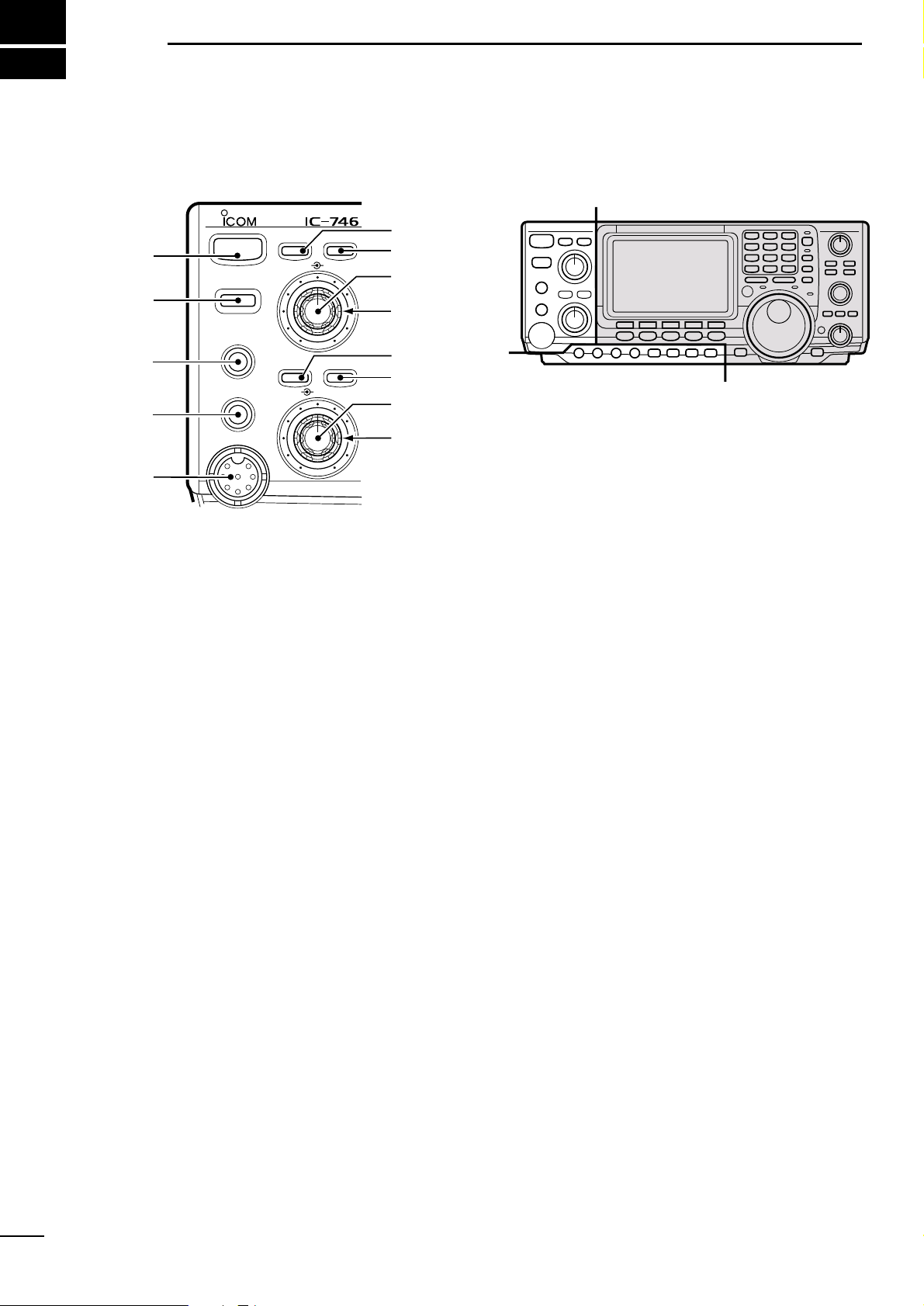
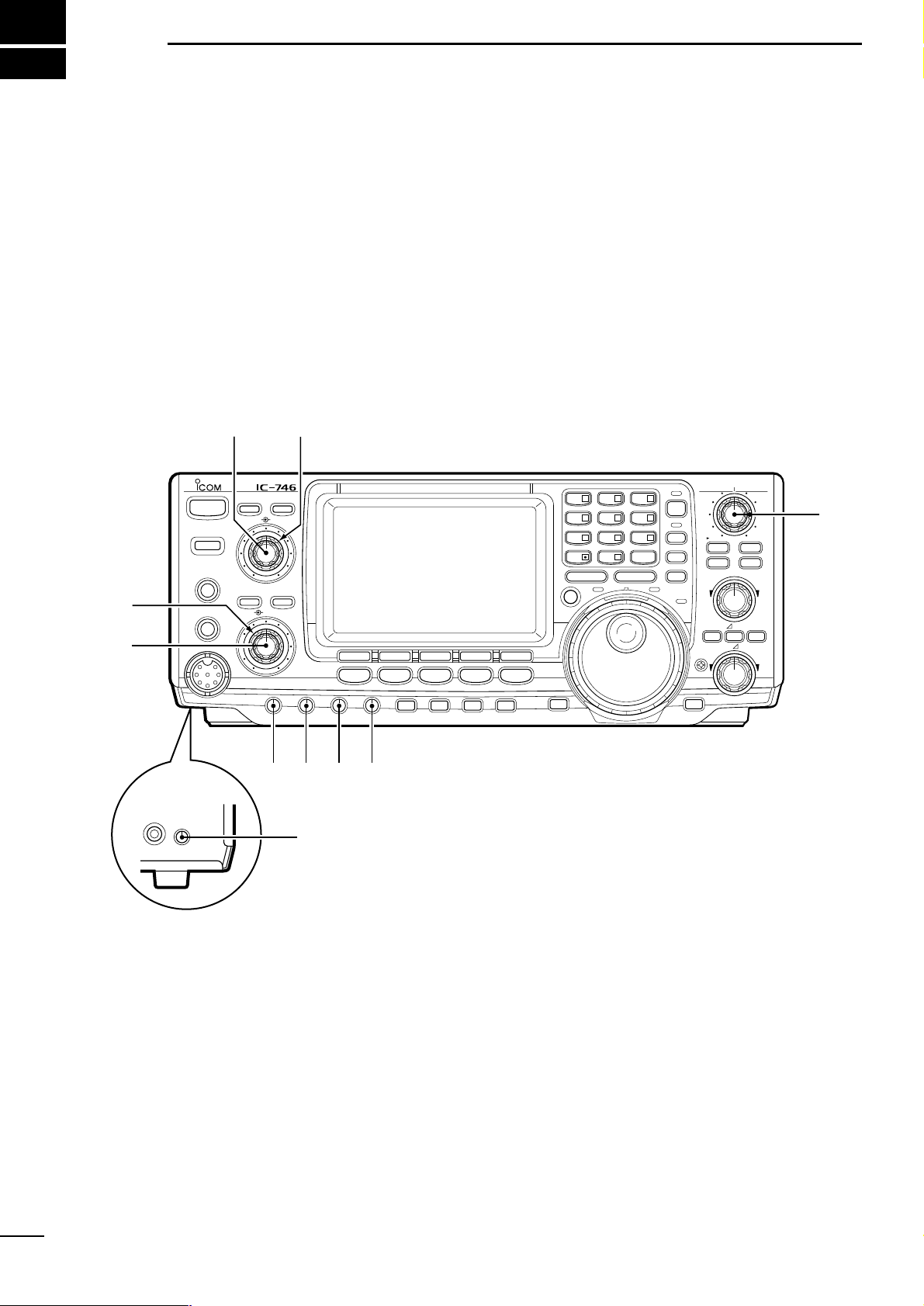
1-1 Front panel
q POWER SWITCH [POWER]
➥ Push momentarily to turn power ON. (p. 11)
• Turn the optional DC power supply ON in advance.
➥ Push and hold to turn power OFF.
w TRANSMIT SWITCH [TRANSMIT]
Toggles between transmit and receive.
• The [TX] indicator lights red while transmitting and the
[RX] indicator lights green when the squelch is open.
e HEADPHONE JACK [PHONES] (p.67)
Accepts headphones.
• When headphones are connected, the internal speaker
or connected external speaker does not function.
r ELECTRONIC KEYER JACK [ELEC-KEY] (p. 67)
Accepts a paddle to activate the internal electronic
keyer for CW operation.
• Selection between the internal electronic keyer, bug-key
and straight key operation can be made in keyer set
mode.
• A straight key jack is separately available on the rear
panel.
• Key polarity (dot and dash) can be reversed in keyer set
mode.
• 4-channel memor y keyer is available for your convenience.
t MICROPHONE CONNECTOR [MIC]
Accepts the supplied or optional microphone.
• See p.85 for appropriate microphones.
• See p.67 for microphone connector information.
y ANTENNA TUNER SWITCH [TUNER] (p. 59)
➥ Tur ns the antenna tuner ON and OFF (bypass)
when pushed momentarily.
➥ Starts to tune the antenna manually when
pushed for 2 sec.
• When the tuner cannot tune the antenna, the tuning
circuit is bypassed automatically after 20 sec.
u ANTENNA SELECTOR SWITCH [ANT] (p.71)
Toggles between the HF and 50 MHz antenna connectors.
i NOISE REDUCTION LEVEL CONTROL [NR]
(p.40)
Adjusts the noise reduction level when the noise reduction function is in use. Set for maximum readability.
o AUDIO PEAK FILTER CONTROL [APF] (p.20)
V aries the peak frequency of the audio peak filter to
pick out a CW signal from interference while the
APF function is ON.
!0 NOISE REDUCTION SWITCH [NR] (p. 40)
Toggles the noise reduction function ON and OFF.
Functions in SSB, CW and RTTY modes.
!1 AUDIO PEAK FILTER/AUTO NOTCH SWITCH
[APF/ANF]
➥ Toggles between the audio peak (p.20) and auto
notch (p. 40) functions.
• The audio peak filter functions in CW mode only; the
auto notch functions in SSB, FM and AM modes only.
• The APF or ANF indicator appear in the display depending on which function is selected.
➥ When the APF indicator appears, push this
switch for 1 sec., one or more times to select 320
Hz, 160 Hz or 80 Hz bandwidths.
• Use the [APF] control to vary the peak frequency.
!2 AF CONTROL [AF] (inner control; p. 12)
Varies the audio output level from the speaker.
PHONES
TRANSMIT
POWER
TUNER ANT
ELEC-KEY
MIC
NR APF/ANF
AF RF/SQL
NR APF
1
2
3
4
5
6
7
8
9
!1
!2
!3
!0
Å
Å
ı
3
1
PANEL DESCRIPTION
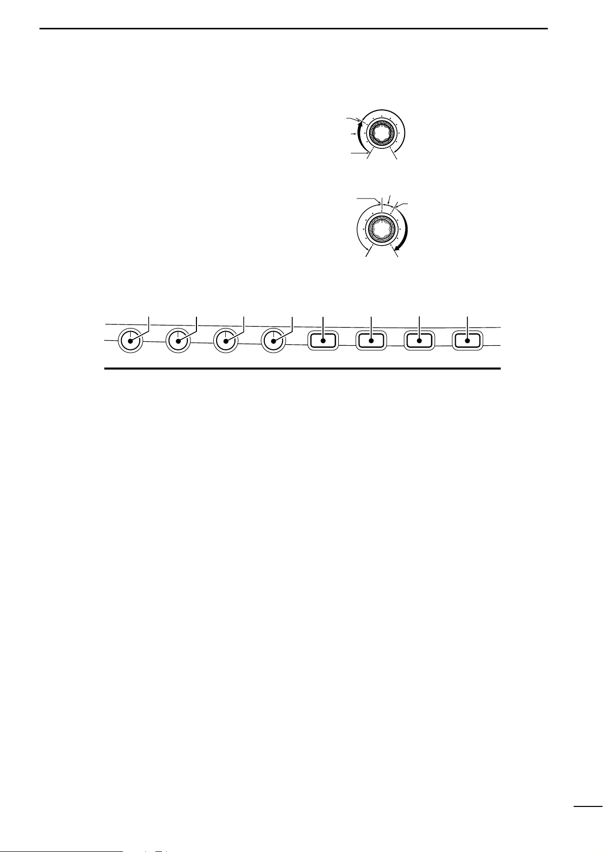
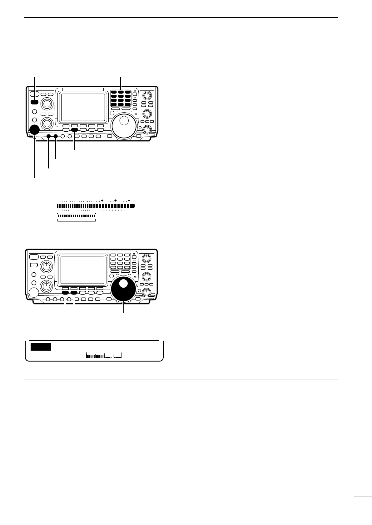
!3 RF GAIN/SQUELCH CONTROL [RF/SQL] (p.12)
Adjusts the RF gain and squelch threshold level.
The squelch removes noise output from the speak er
(closed condition) when no signal is received.
• The squelch is particularly effective for FM. It is also
available for other modes.
• The control can be set as the RF gain control only
(squelch is fixed open) or squelch control (RF gain is
fixed at maximum) in set mode.
!4 MIC GAIN CONTROL [MIC GAIN]
Adjusts the microphone input gain.
!5 RF POWER CONTROL [RF PWR] (p. 84)
Continuously varies the RF output power from minimum (2 W*) to maximum (100 W*).
*AM mode: 2–40 W, other modes: 5–100 W.
!6 CW PITCH CONTROL [CW PITCH] (p.20)
Shifts the received CW audio pitch and monitored
CW audio pitch without changing the operating frequency.
• The pitch can be changed from 300 to 900 Hz in approx.
3 Hz steps.
!7 ELECTRONIC CW KEYER SPEED CONTROL
[KEY SPEED] (p.22)
Adjusts the internal electronic CW keyer’s speed.
• 6 wpm to 60 wpm can be set.
!8 PREAMP/ATTENUATOR SWITCH [P.AMP/ATT]
(p.38)
➥ Push momentarily to toggle between preamp-1
and preamp-2.
➥ Push for 1 sec. to toggle the attenuator function
ON and OFF.
!9 NOISE BLANKER SWITCH [NB] (p. 39)
Toggles the noise blanker ON and OFF.The noise
blanker reduces pulse-type noise such as that generated by automobile ignition systems.This function
cannot be used for FM, or non pulse-type noise.
@0 VOX/BREAK-IN SWITCH [VOX/BK-IN]
➥ In SSB, AM and FM modes, push momentarily to
turn the VOX function ON; push for 1 sec. to turn
the VOX function OFF. (p. 43)
➥ In CW mode, push momentarily to select semi
break-in, full break-in or break-in OFF; push for 2
sec. to enter break-in set mode. (p. 44)
@1 MONITOR SWITCH [MONI] (p.45)
➥ Push to toggle the monitor function ON and OFF.
➥ Push for 2 sec. to enter and exit monitor set
mode.
Adjustable
range
Maximum
RF gain
Maximum
RF gain
sensitivity
Minimum
RF gain
sensitivity
• Setting squelch
• Setting RF gain
Squelch
threshold
Squelch
open
S-meter squelch
operating
range
S-meter squelch
threshold
Noise squelch
operating range
MIC GAIN RF PWR CW PITCH P.AMP/ATTKEY SPEED NB VOX/BK-IN MONITOR
!4 !5 !6 !7 !8 !9
@0
@1
ı
4
1
PANEL DESCRIPTION
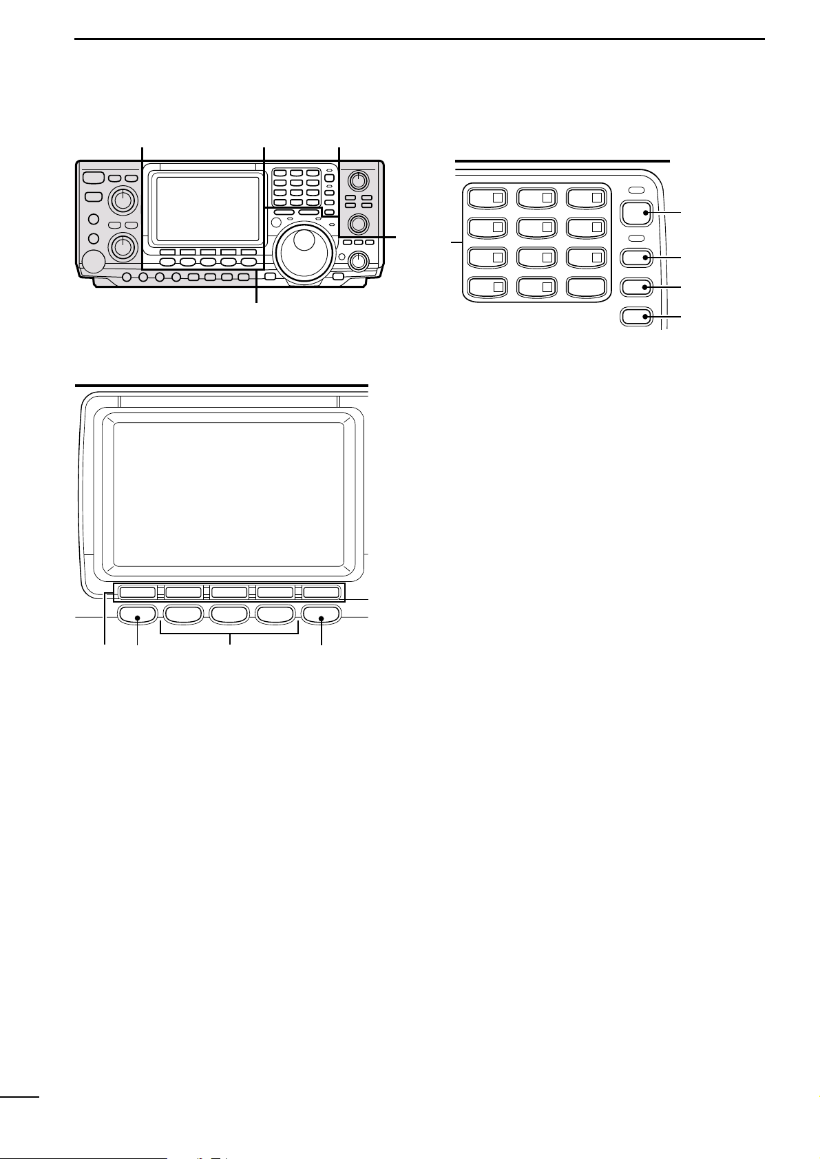
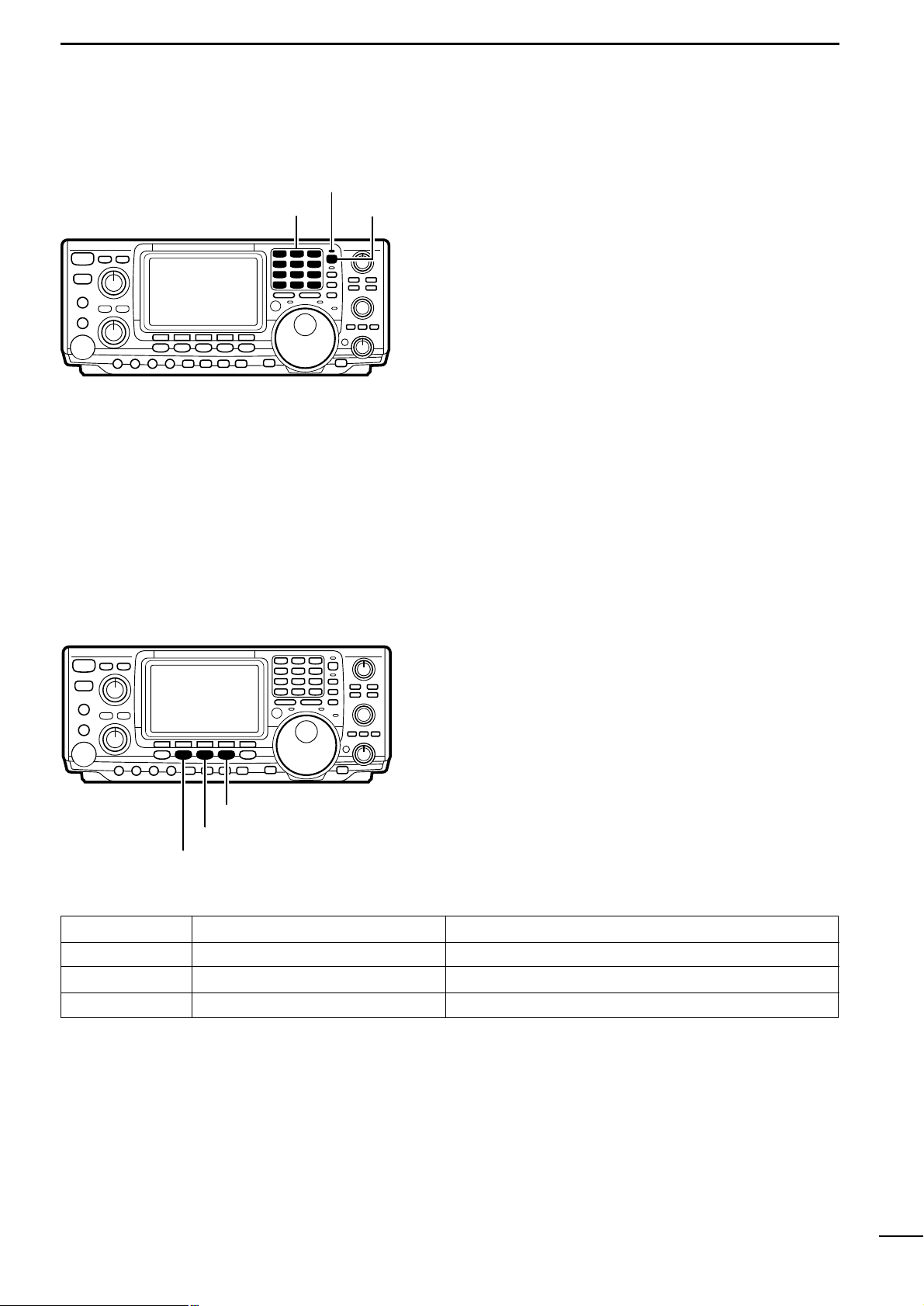
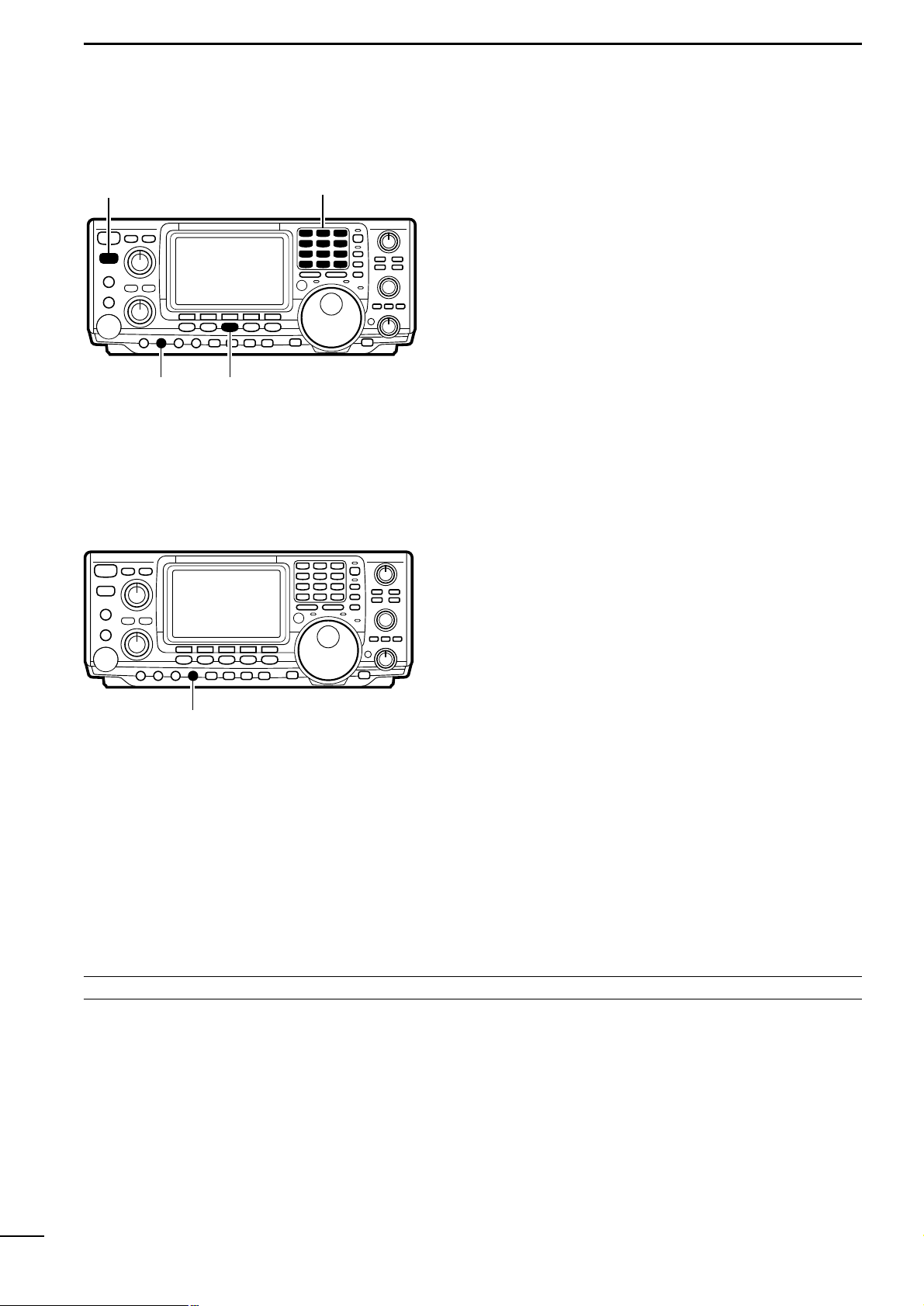
@2 MULTI-FUNCTION SWITCHES (p. 8)
➥ Push to select the functions indicated in the func-
tion display above these switches.
➥ Push to input a character for memory keyer pro-
gramming or memory name.
@3 MENU SWITCH [MENU] (p. 8)
Push to change the set of functions assigned to the
multi-function switches.
• Toggles between menu set 1 and menu set 2.
@4 MODE SWITCHES (p. 17)
Select an operating mode.
• Push [SSB] to toggle between LSB and USB.
• Push [CW/RTTY] to toggle between CW and RTTY.
• Push [CW/RTTY] for 1 sec. to toggle between CW and
CW-R or RTTY and RTTY-R.
@5 FILTER SWITCH (pgs. 42, 78)
➥ Push momentarily to toggle between normal and
narrow IF filters for the selected operating mode.
➥ Push for 1 sec. to enter normal or narrow IF filter
set mode.
Ç Î
´
TS
1.8
1
3.5
2
7
3
10
4
14
5
18
144ENT
6
21
7
•
24
8
28
9
GENE
50
0
A/B
SPLIT
F-INP
@7
@8
@9
#0
@6
Î
F1 F2 F3 F4 F5
MENU SSB
CW/RTTY
AM/FM FILTER
HF/VHF TRANSCEIVER
@2
Ç
@3
@4
@5
@6 KEYPAD (p. 14)
➥ Push a key to select an operating band.
• [GENE] selects the general coverage band.
➥ Push the same key 2 or 3 times to call up stacked
frequencies in the band.
• Icom’s band stacking register memorizes 3 frequencies (and modes) in each band.
@7 FREQUENCY INPUT SWITCH [F-INP] (p.17)
➥ Toggles keypad input between frequency and
band.
• The LED lights green to indicate the switch is set for
frequency input.
@8 SPLIT SWITCH [SPLIT] (p. 47)
Push to toggle the split function ON and OFF.
• The LED lights green to indicate split operation (between
VFO A and VFO B is selected).
@9 A/B SWITCH [A/B] (p. 13)
➥ Push to toggle between VFO A and VFO B.
➥ Push for 1 sec. to equalize the contents of VFO
A and VFO B.
#0 QUICK TUNING STEP SWITCH [TS] (p. 15)
➥ Turns the quick tuning step ON and OFF.
• While the quick tuning indicator is displayed, the frequency can be changed in programmed kHz steps.
• 1, 5, 9 and 10 kHz quick tuning steps are available.
➥ While the quick tuning step is OFF, turns the 1 Hz
step ON and OFF when pushed for 2 sec.
• 1 Hz indications appear in both readouts and the frequency can be changed in 1 Hz steps.
➥ While the quick tuning step is ON, enters the
quick tuning step mode when pushed for 2 sec.

5
1
PANEL DESCRIPTION
#1 TUNING DIAL
Changes the displayed frequency, selects set mode
items, etc.
#2 TRANSMIT FREQUENCY CHECK SWITCH [XFC]
(pgs.34, 38, 45, 47)
Monitors the transmit frequency when pushed and
held when the split frequency function is ON.
• While pushing this switch, the transmit frequency can be
changed with the tuning dial, keypad or the memo pad.
• When the split lock function is turned ON, pushing [XFC]
cancels the dial lock function.
#3 MEMO PAD WRITE SWITCH [MP-W] (p.54)
Programs the selected readout frequency and operating mode into a memo pad.
• The 5 most recent entries remain in memo pads.
• The transmit frequency is programmed when pushed to-
gether with [XFC].
• The memo pad capacity can be expanded from 5 to 10
in set mode for your convenience.
#4 TRANSMIT INDICATOR [TX]
Lights red while transmitting.
#5 MEMO PAD READ SWITCH [MP-R] (p. 54)
Each push calls up a frequency and operating mode
in a memo pad. The (or 10) most recently programmed frequencies and operating modes can be
recalled, starting from the most recent.
• The memo pad capacity can be expanded from 5 to 10
in set mode for your convenience.
#6 RECEIVE INDICATOR [RX]
Lights green while receiving a signal or when the
squelch is open.
#7 LOCK INDICATOR [LOCK] (p. 40)
Lights when the dial lock function is activated.
#8 SPEECH SWITCH [SPEECH] (p. 77)
Announces the selected readout frequency when an
optional UT-102 is installed.
#9 LOCK SWITCH [LOCK] (p. 40)
Turns the dial lock function ON and OFF.
$0 RIT SWITCH [RIT] (p. 38)
➥ Turns the RIT function ON and OFF when
pushed.
• Use the [RIT/:TX] control to vary the RIT frequency .
➥ Adds the RIT shift frequency to the operating fre-
quency when pushed for 2 sec.
$1 :TX SWITCH [:TX] (p. 45)
➥ Turns the :TX function ON and OFF when
pushed.
• Use the [RIT/:TX] control to vary the :TX frequency.
➥ Adds the :TX shift frequency to the operating
frequency when pushed for 2 sec.
$2 CLEAR SWITCH [CLEAR] (pgs. 38, 45)
Clears the RIT/:TX shift frequency when pushed
for 2 sec.
$3 RIT/:TX CONTROL [RIT/:TX] (pgs. 38, 45)
Shifts the receive and/or transmit frequency without
changing the transmit and/or receive frequency
while the RIT and/or :TX functions are ON.
• Rotate the control clockwise to increase the frequency,
or rotate the control counterclockwise to decrease the
frequency.
• The shift frequency range is ±9.999 kHz in 1 Hz steps
(or ±9.99 kHz in 10 Hz steps).
$4 BRAKE ADJUSTMENT SCREW (p. 65)
Adjusts the tension of the tuning dial.
• Rotate clockwise to increase the tension; counterclockwise to decrease the tension.
LOCK
XFC
RIT/ TX
SPEECH LOCK
TX RX
MP-W MP-R
RIT
TX CLEAR
´
#1
#2 #3
#4
#5 #6 #7
#8
#9
$0
$1 $2
$3
$4

6
1
PANEL DESCRIPTION
$5 PASSBAND TUNING CONTROLS [TWIN PBT]
(p.41)
Adjust the receiver’s “passband width” of the 455
kHz and 9 kHz IF filters for the inner and outer controls, respectively.
• Passband width and center frequency are displayed in
the function display.
• Set to the center positions when not in use.
• Variable r ange depends on the filter selection. ±1.29 kHz
in 15 Hz steps and ±258 Hz in 3 Hz steps are available.
$6 VFO/MEMORY SWITCH [V/M]
➥ Toggles the selected readout operating mode be-
tween VFO mode and memory mode when
pushed.
➥ Transfers the memory contents to VFO when
pushed for 2 sec.
$7 CALL CHANNEL SWITCH [CALL] (p. 51)
Brings up the call channel.
• When the call channel is displayed, push this switch to
exit call channel mode.
$8 MEMORY WRITE SWITCH [MW] (p. 51)
Stores the selected readout frequency and operating mode into the displayed memory channel when
pushed for 2 sec.
• This function is available in both VFO and memory
modes.
$9 MEMORY CLEAR SWITCH [M-CL] (p.50)
Clears the selected readout memory channel contents when pushed for 2 sec.in memory mode.
• This switch does not function in VFO mode.
%0 MEMORY CHANNEL CONTROL [M-CH] (p.49)
Selects a memory channel.
• Rotate clockwise to increase the memory channel; rotate counterclockwise to decrease the memory channel.
Ï
M-CH
V/M CALL
M VFO
TWIN PBT
MW M-CL
Ï
$5
$6 $7
$8 $9
%0
wq
[ANT1][ANT2]
[ANT144MHz]
[REMOTE]
[SP]
[KEY JACK] [ACC1/2] [SEND]
[ALC]
1-2 Rear panel
q CALIBRATION POT [CAL]
This is used for frequency calibration (p. 65).
• The transceiver has been adjusted and calibrated thoroughly at the factory. Under normal circumstances, the
frequency does not need to be recalibrated.
w COMPRESSION LEVEL CONTROL [COMP GAIN]
(p.46)
Adjusts the speech compression level in SSB.
☞ NOTE: Refer to “12-2 Rear panel”(p.68) for details
concerning other rear panel connectors, etc.

7
1
PANEL DESCRIPTION
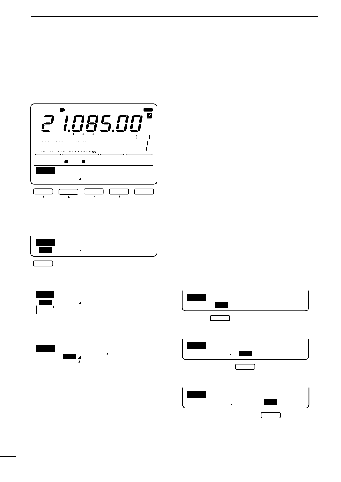
q ANTENNA TUNER INDICA TORS (pgs.59, 79)
➥ “TUNE” appears when the antenna tuner is ON;
“TUNE” appears and flashes dur ing manual tun-
ing.
➥ “EXT” appears when the optional AH-4 external
HF antenna tuner is connected to [ANT1].
w ANTENNA INDICATORS (p. 71)
Indicate which antenna connector is in use for
HF/50 MHz.
e MODE INDICATORS (p. 7)
Indicate the selected operating mode.
r NARROW FILTER INDICATOR (p.42)
Appears when the narrow IF filter is selected.
t
1
⁄4 TUNING DIAL SPEED INDICATOR (p. 39)
Appears when the tuning dial is set so that one revolution is equal to 1⁄4 of the normal revolution.
y FREQUENCY READOUT
Shows the operating frequency.
u MULTI-FUNCTION METER INDICATION
Displays S-meter reading during receive;“P
0,”“ALC”
and “SWR”meters can be selected for transmit.
i RIT/
:TX INDICATORS (pgs.38, 45)
Appear during RIT or :TX operation and indicate
the frequency offset.
o VFO/CALL/MEMORY INDICATORS
Indicate whether VFO A, VFO B, the call channel or
memory mode is selected.
!0 BLANK MEMORY INDICATOR (p.49)
Appears when the selected memory channel is
blank.
!1 SELECT MEMORY INDICATOR (p.57)
Appears when the selected memory channel is a
“select” memory channel.
BLANK
1
4
MW
APF
CH
MEMO
VFOB
VFOA
SEL
NR
ANFTSQLXFC
TUNE
ANT RTTY RAMWFM
NBMONICOMP
DUPSPLIT
RIT TX
OFFAGCATTAMP
P.BKVOX
SWR
ALC
Po
S
1
20 50
3
3211.5
579 20 40 60
IN
N
100%
EXT
NAR
CALL
21
F
1
2
F
S
LSB
USBCW
M1
AGCDUPCMPTCNSCP
BLANK
MW
APF
CH
MEMO
VFOB
VFOA
SEL
NR
ANFTSQLXFCNBMONICOMP
DUPSPLIT
RIT TX
OFFAGCATTAMP
P.BKVOX IN
N
CALL
F
1
2
F
S
1
23
4
5
6
7
8
9
!1
!0
!2
!3 !4
!5
!6
!7
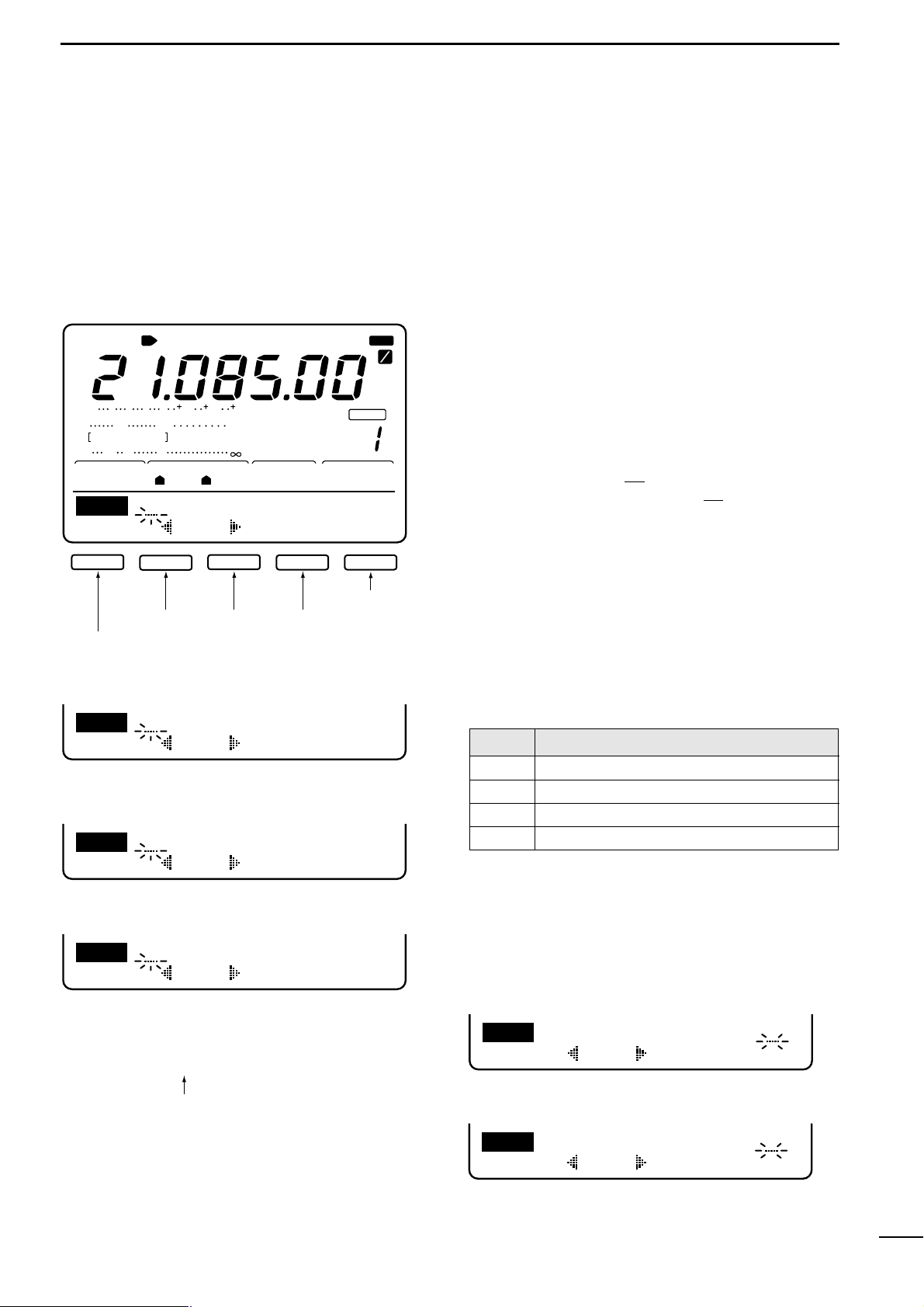
!2 MEMORY CHANNEL INDICATOR (p.49)
Shows the selected memory channel.
!3 TRANSMIT FUNCTION INDICATORS
Indicate functions selected for transmit.
!4 RECEIVE FUNCTION INDICATORS
Indicate functions selected for receive.
!5 SPLIT FUNCTION INDICATOR
Appears during split operation.
!6 DSP FUNCTION INDICATORS
Appear when DSP functions are selected.
!7 MULTI-FUNCTION SWITCH INDICATORS (p. 8)
Indicate the functions assigned to the multi-function
switches (F1–F5).
1-3 Function display
8
2
MENU SELECTION
M1M2M3M4 -1
BLANK
CH
ANT
USB
AGCAMP
P.
SWR
ALC
Po
S
1
20 50
3
3211.5
579 20 40 60
100%
1
1
S
M1
AGCDUPCMPTCNSCP
F1
F2
F3 F4 F5
TCN
LH
0
SSBTXTone
SCP
STEP
0.5k
F1 F5
F1
F2
F3 F4 F5
M1
AGCDUP1/4KEYSCP
F2
F3 F4 F5
SNDEDT001SET
KEY
F1
F2
F3 F4 F5
001
SND
50%
SideToneLevel
SET
F1
F2
Normal
NumberStyle
001
F1
F2
F1
F2
F3 F4 F5
EDT
M1
DELSPC
CQTESTCQTEST
F5
F4
F3
F1
F2
F3 F4 F5
M1
AGCDUP1/4RTYSCP
2125
RTTYMark
RTY
F1
F2
F1
F2
F3 F4 F5
M1
AGCDUPTONTSQSCP
F1
F2
F3 F5
M1
AGCDUPCMPSCP
VFOA
SSB MODE
BAND SCOPE MENU
RTTY MODE
AM MODE
FM MODE
CW MODE
To band scope
menu
EDIT MENU
CONTEST NUMBER MENU
KEYER SET MODE
MEMORY KEYER MENU
SEND MENU
(p. 24)
(p. 23)
(p. 27)
(p. 26)
(p. 25)
(
p. 37
)
(p. 29)
(p. 19)
RTTY MENU
TONE CONTROL MENU
To band scope
menu
To band scope
menu
To band scope
menu
To band scope
menu
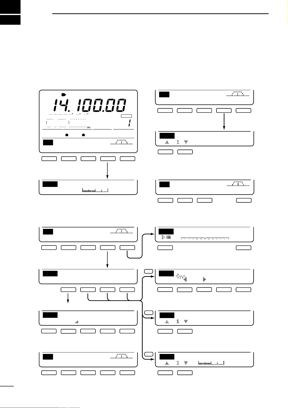
2-1
Menu set 1 flow chart
Pushing [MENU] toggles between menu set 1 (M1)
and menu set 2 (M2) in the function display.
Depending on the mode and menu item selected, the
action of the multi-function keys ([F1] to [F5]) changes.
9
2
MENU SELECTION
F5
F2
F3
F5
BLANK
CH
ANT
USB
AGCAMP
P.
SWR
ALC
Po
S
1
20 50
3
3211.5
579 20 40 60
100%
1
1
S
M2
SCNMEMLCDSET
F1
F2
F3 F5
SCN
10k
+
-
∂F
PRO∂FFINSPNSET
F1
F2
F3 F4 F5
SCN
10k
+
-
∂F
MEM∂FSELSPNSET
F-1
F-2
F-3 F-4 F-5
SCANSpeed
HIGH
SET
F1
F2
F1 F5
MEM
14.1000USB
EDT()SEL
EDT
ABC
DELSPC
F1
F2
F3 F4 F5
LCDContrast
50%
LCD
F1
F2
VFO MODE
MEMORY MODE
50%
BeepLevel
SET
F1
F2
VFOA
(p. 55)
SET MODE
SCAN SET MENU
LCD MENU
MEMORY NAME MENU
NAME EDIT MENU
(p. 53)
(p. 66)
(p. 53)
(p. 60)
SCAN MENU (pgs. 56–58)
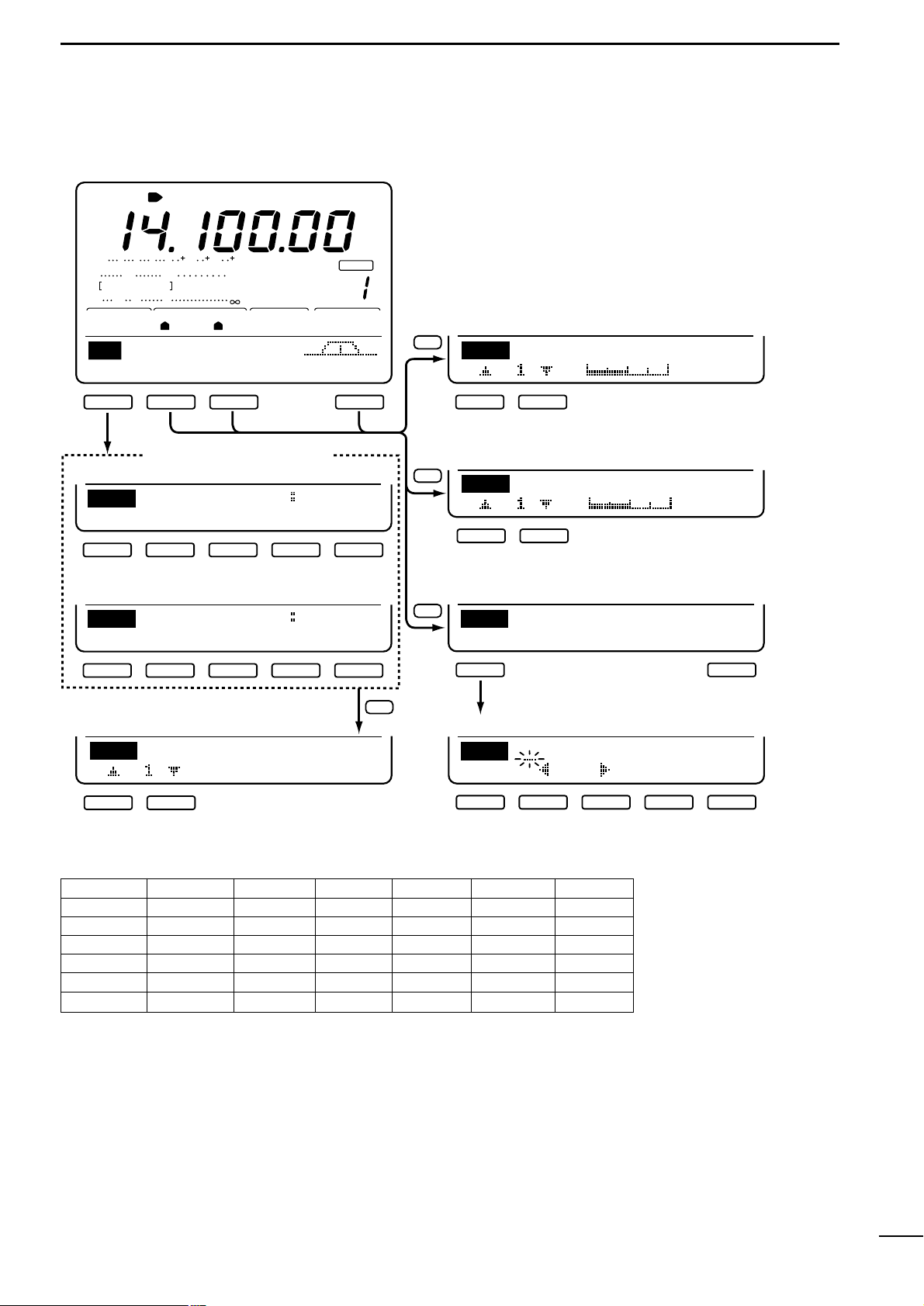
2-2
Menu set 2 flow chart
MENU MODE F1 F2 F3 F4 F5
SSB q AGC w DUP e CMP r TCN t SCP
CW AGC DUP y 1/4 u KEY SCP
M1 RTTY AGC DUP 1/4 i RTY SCP
AM AGC DUP CMP SCP
FM AGC DUP o TON !0 TSQ SCP
M2 ALL !1 SCN !2 MEM !3 LCD !4 SET
q AGC (auto gain control) : p. 39
w DUP (duplex) : p. 35
e CMP (speech compressor) : p. 46
r TCN (tone control) : p.20
t SCP (band scope) : p. 37
y 1/4 (dial rate) : p. 39
u KEY (CW key) : p.24
i RTY (RTTY) : p.30
o TON (repeater tone) : p. 35
!0 TSQ (tone squelch) : p. 33
!1 SCN (scan) : p. 55
!2 MEM (memory names) : p. 53
!3 LCD (function display) : p.66
!4 SET (set mode) : p. 60
10
3
BASIC OPERATION
3-1
Before operating
Å BEFORE APPLYING POWER
Before applying power for the first time, check the following points:
➥ Is the connected external power supply capable of
delivering more than 20 A?
➥ Are the antenna(s) connected properly?
• [ANT1/2]: HF/50 MHz antenna
• [144MHz]: 144 MHz antenna
➥ Is the transceiver properly grounded? (p.70)
➥ Is external equipment, such as a linear amplifier
connected properly? (p.79)
➥ Make sure the front panel switches and controls are
set as illustrated below.
F1 F2 F3 F4 F5
PHONES
TRANSMIT
POWER
TUNER ANT
ELEC-KEY
MIC
M-CH
V/M CALL
M VFO
LOCK
XFC
TWIN PBT
NR APF/ANF
AF RF/SQL
NR APF
RIT/ TX
MIC GAIN RF PWR CW PITCH P.AMP/ATTKEY SPEED NB VOX/BK-IN MONITOR
SPEECH LOCK
TX RX
MENU SSB
CW/RTTY
AM/FM FILTER
MW
MP-W
HF/VHF TRANSCEIVER
MP-R TS
M-CL
RIT TX CLEAR
1.813.527
3
10414518
144ENT
6
21
7
24828
9
GENE
50
0
A/B
SPLIT
F-INP
Rearpanel
1
2
3
4
5
6
789
!0
q Rotate [NR] max. counterclockwise.
w Set [APF] to the center position.
e Set [TWIN PBT] to the center position.
r Rotate [AF] max. counterclockwise.
t Set [RF/SQL] to the center position.
y Rotate [MIC GAIN] max. counterclockwise.
u Rotate [RF PWR] max. counterclockwise.
i Set [CW PITCH] to the center position.
o Rotate [KEY SPEED] max. counterclockwise.
!0 Rotate [COMP GAIN] max. counterclockwise.
11
3
BASIC OPERATION
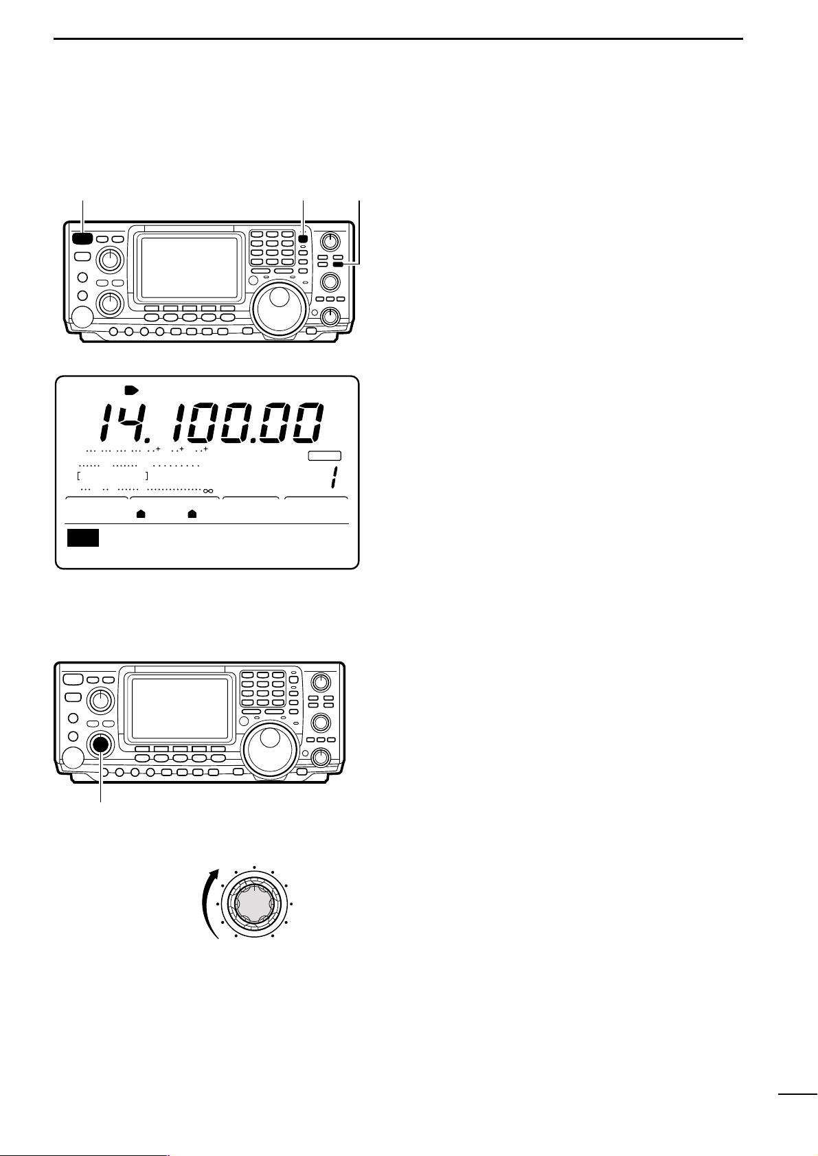
ı APPLYING POWER
Ç ADJUSTING VOLUME
Rotate [AF] to obtain a comfortable listening level.
• Clockwise rotation increases audio output; counterclockwise decreases audio output.
When applying power to the transceiver for the first
time, it’s a good idea to reset the CPU (see p. 81 for
details) as follows:
While pushing [F-INP] + [M-CL], push [POWER] to turn
power ON.
• After the CPU has been reset, turn power ON by pushing
[POWER] only.
• Push [POWER] for 1 sec.to turn power OFF.
[F-INP]
[M-CL]
[POWER]
BLANK
CH
ANT
USB
AGCAMP
P.
SWR
ALC
Po
S
1
20 50
3
3211.5
579 20 40 60
100%
1
1
S
M1
AGCDUPCMPTCNSCP
VFOA
☞ NOTE: When first applying power or when operat-
ing in cold environments, the display may flicker or
appear faint.This is normal and will disappear once
the transceiver has warmed up.
[AF]
Increasing audio
output

12
3
BASIC OPERATION
3-2
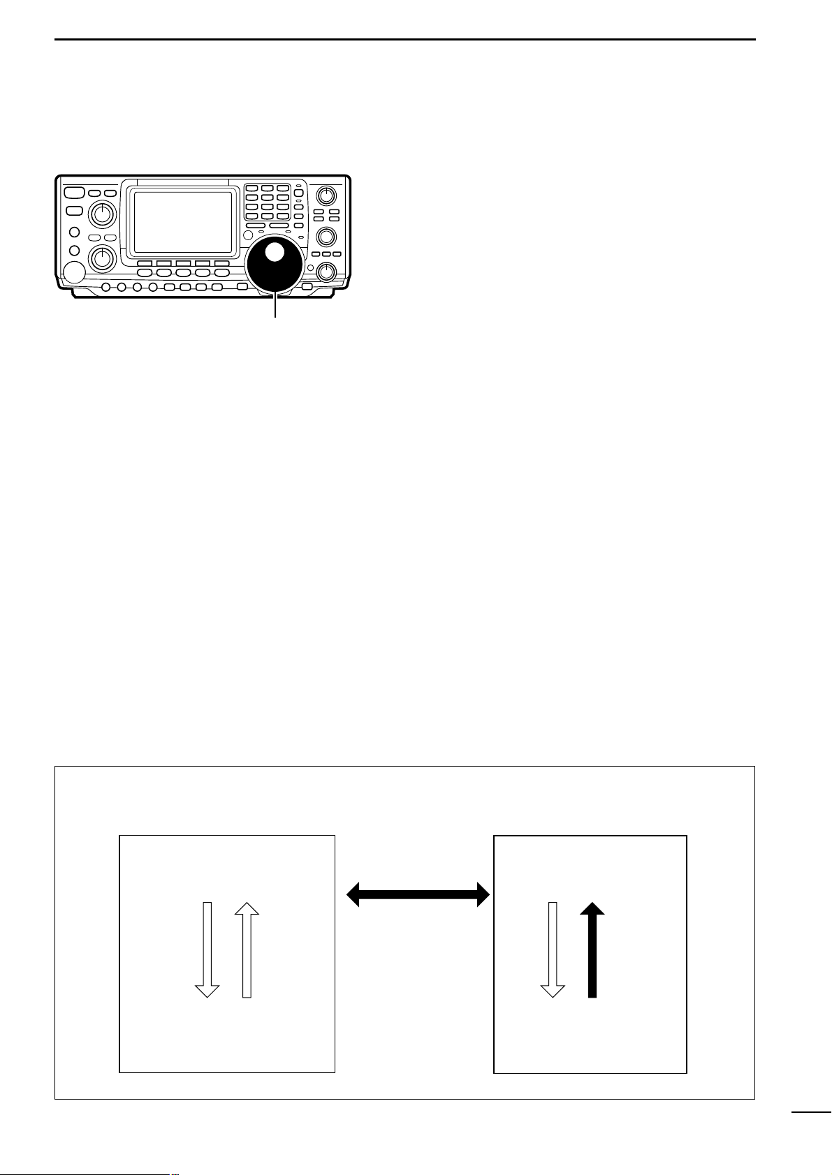
Squelch and receive (RF)
sensitivity
[RF/SQL]
RF gain
range
RF gain
operating
range
Squelch
open
Squelch
threshold
Squelch
open
S-meter
squelch
range
S-meter squelch
operating
range
S-meter squelch
threshold
Noise squelch
range
Noise squelch
operating range
RF gain
max.
sensitivity
Max.
RF gain
sensitivity
Minimum
RF gain
sensitivity
Max. RF gain
Adjusts the RF gain and squelch threshold level. The
squelch removes noise output from the speaker
(closed condition) when no signal is received.
• The squelch is particularly effective for FM. It is also available for other modes.
• The control can be set as the RF gain control only (squelch
is fixed open) or squelch control (RF gain is fixed at maximum) in set mode (p.61). See below left.
• The 11 to 12 o’clock position is recommended for any setting of the [RF/SQL] control.
When setting as RF gain/squelch control
When setting as RF gain (squelch is fixed open)
Adjusting RF gain (receive sensitivity)
Normally, [RF/SQL] is set to the 11 o’clock position.
Rotate [RF/SQL] to the 11 o’clock position for maximum sensitivity.
• Rotating counterclockwise from the maximum position reduces sensitivity.
• The S-meter indicates receive sensitivity.
When setting as squelch (RF gain is fixed at max.)
Adjusting squelch (removing non-signal noise)
Rotate [RF/SQL] clockwise, when receiving no signal,
until the noise just disappears.
• [RX] indicator light goes out.
• Rotating [RF/SQL] past the threshold point invokes the S-
meter squelch—this allows you to set a minimum signal
level needed to open the squelch.
SET MODE
RF + SQL
(default)
SQL
RF
OPERATION
Can be used in all modes.
Functions as noise squelch or Smeter squelch in FM; S-meter
squelch only in other modes.
➥ Operates as a squelch control.
• RF gain is fixed at max.sensitivity.
➥ Operates as an RF gain control.
• Squelch is fixed open.

13
3
BASIC OPERATION
3-3
Selecting VFO/memory mode
[V/M]
■ VFO DISPLAY (default)
BLANK
CH
ANT
USB
AGCAMP
P.
SWR
ALC
Po
S
1
20 50
3
3211.5
579 20 40 60
100%
1
1
S
M1
AGCDUPCMPTCNSCP
VFOA
■ MEMORY DISPLAY (default)
CH
AGCAMP
P.
SWR
ALC
Po
S
1
20 50
3
3211.5
579 20 40 60
100%
1
S
M1
AGCDUPCMPTCNSCP
MEMO
BLANK
[A/B]
Rotating the tuning dial selects frequencies in VFO
mode or pre-programmed memories in memory mode.
Push [V/M] to toggle between memory and VFO
modes.
• Pushing [V/M] for 2 sec. transfers the contents of the selected memory channel to VFO mode (p.50).
3-4
Toggling between VFO A/B
and transferring contents
In VFO mode, VFO A or VFO B can be selected.In addition, contents can be transferred between them.
➥ Push [A/B] to toggle between VFO A and VFO B.
➥ Push [A/B] for 1 sec. to transfer the contents of the
displayed VFO to the undisplayed VFO.
BLANK
CH
ANT
USB
AGCAMP
P.
SWR
ALC
Po
S
1
20 50
3
3211.5
579 20 40 60
100%
1
1
S
M1
AGCDUPCMPTCNSCP
VFOA
■ WHEN OPERATING IN VFO A
BLANK
CH
ANT
USB
AGCAMP
P.
SWR
ALC
Po
S
1
20 50
3
3211.5
579 20 40 60
100%
1
1
S
M1
AGCDUPCMPTCNSCP
VFOB
■ WHEN OPERATING IN VFO B

14
3
BASIC OPERATION
3-5 Setting a band and frequency
Å SETTING AN OPERATING BAND
The transceiver has a triple band stacking register.This
means that the last 3 operating frequencies and
modes used on a particular band are automatically
memorized.
See the table below f or a list of the bands a vailable and
the default settings for each register.
Bandkeys
1.8
1
3.5
2
7
3
10
4
14
5
18
144ENT
6
21
7
•
24
8
28
9
GENE
50
0
■ USING THE BAND STACKING REGISTERS
[EXAMPLE]: 21 MHz band
➀ Push [21¶], then select a frequency and an operat-
ing mode.
• Frequency and operating mode are memorized in the
first band stacking register.
➁ Push [21¶] again, then select another frequency
and operating mode.
• This frequency and operating mode are memorized in
the second band stacking register.
➂ Push [21¶] again, then select another frequency
and operating mode.
• This frequency and operating mode are memorized in
the third band stacking register.
• When a fourth frequency and operating mode are selected on a band, the first register is overwritten.
BAND REGISTER 1 REGISTER 2 REGISTER 3
1.9 MHz 1.900000 CW 1.910000 CW 1.915000 CW
3.5 MHz 3.550000 LSB 3.560000 CW 3.580000 LSB
7 MHz 7.050000 LSB 7.060000 CW 7.020000 CW
10 MHz 10.120000 CW 10.130000 CW 10.140000 CW
14 MHz 14.100000 USB 14.200000 USB 14.050000 CW
18 MHz 18.100000 USB 18.130000 USB 18.150000 USB
21 MHz 21.200000 USB 21.300000 USB 21.050000 CW
24 MHz 24.950000 USB 24.980000 USB 24.900000 CW
28 MHz 28.500000 USB 29.500000 USB 28.100000 CW
50 MHz 50.100000 USB 50.200000 USB 51.100000 FM
145 MHz 145.000000 USB 145.100000 FM 145.200000 FM
General 15.000000 USB 15.100000 USB 15.200000 USB
15
3
BASIC OPERATION
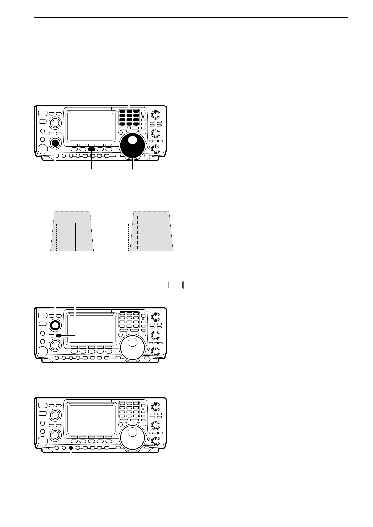
ı SETTING A FREQUENCY WITH THE
TUNING DIAL
Frequencies can be selected with the tuning dial or directly with the keypad (p. 17). When using the tuning
dial, the frequency changes according to the set tuning step.Tuning step defaults differ depending on operating mode as shown below.
SSB/CW/RTTY: 10 Hz
AM: 1 kHz
FM: 10 kHz
➥ Rotate the tuning dial clockwise to increase the fre-
quency; counterclockwise to decrease the frequency.
Tuning dial
■ BAND EDGE WARNING BEEPS
When selecting a frequency that lies outside of a
band’s specified frequency range, a warning beep
sounds.
This function can be turned off in set mode, if desired
(p.61).
Tuning steps automatically change according to the
rate at which the tuning dial is rotated.
When rotated slowly, one complete revolution of the
tuning dial changes the frequency 5 kHz (10 Hz tuning
steps); when rotated quickly, one complete revolution
of the tuning dial changes the frequency 25 kHz (50
Hz tuning steps).
Rotate the tuning dial to change the frequency in 10
Hz steps or use the microphone [UP]/[DN] keys to
change the frequency in 50 Hz steps. The diagram
below illustrates how to change the tuning steps.
■ AUTO TUNING STEPS
■ CHANGING TUNING STEPS
TS function OFF
Fine tuning
(
1
Hz)
TS function OFF
(1 kHz)*
*FM mode only 10 kHz
TS set mode
(0.1, 1, 5, 9, 10,
12.5, 20, 25 kHz)
SSB/CW/RTTY mode only
All modes
[TS]
momentarily
[TS]
momentarily
[TS]
2 sec.
[TS]
2 sec.
[TS]
2 sec.
• Using the [TS] switch

16
3
BASIC OPERATION
■ TOGGLING THE TS FUNCTION ON AND OFF The tuning step function can be turned ON and OFF.
When the TS function is ON (default), rotating the tuning dial changes the frequency in the set tuning steps.
➀ Push [TS] to turn the tuning step function ON, if nec-
essary.
• The TS indicator, “Z” appears.
➁ Rotate the tuning dial to change the frequency ac-
cording to the set tuning step.
➂ Push [TS] again to turn the tuning step function
OFF.
• The TS indicator, “Z” disappears.
■ TUNING STEP PROGRAM MODE When the tuning step function is ON, tuning step pro-
gram mode can be selected. This mode is used to
change the set tuning steps.
➀ While the tuning step function is ON, (“Z” appears),
push [TS] for 2 sec. to enter tuning step program
mode.
➁ Rotate the tuning dial to select the desired tuning
step.
• 0.1, 1, 5, 9, 10, 12.5, 20 and 25 kHz can be selected.
• Tuning steps can be set individually for each operating
mode.
➂ Push [TS] again to exit tuning step program mode.
■ 1 Hz TUNING For critical tuning, a 1 Hz tuning step can be selected.
➀ While the tuning step function is OFF, (“Z” does not
appear), push [TS] for 2 sec.
• The 1 Hz indicator appears.
➁ Rotate the tuning dial to change the frequency in 1
Hz steps.
• When changing the frequency via the microphone, the
frequency changes in 50 Hz steps, regardless of whether
the 1 Hz tuning step is selected or not.
➂ Push [TS] for 2 sec. again (while the tuning step
function is OFF) to turn the 1 Hz tuning step OFF.
Tuning dial
[TS]
BLANK
CH
VFOA
ANT
AGCAMP
P.
SWR
ALC
Po
S
1
20 50
3
3211.5
579 20 40 60
100%
1
1
S
M1
F
USB
TS indicator
AGCDUPCMPTCNSCP
BLANK
CH
VFOA
ANT
AGCAMP
P.
SWR
ALC
Po
S
1
20 50
3
3211.5
579 20 40 60
100%
1
1
S
0.1kHz
SSB
TS
F
USB
TS indicator
BLANK
CH
ANT
USB
AGCAMP
P.
SWR
ALC
Po
S
1
20 50
3
3211.5
579 20 40 60
100%
1
1
S
M1
AGCDUPCMPTCNSCP
VFOA
The tuning step defaults are:
SSB/CW/RTTY: 10 Hz
AM: 1 kHz
FM: 10 kHz
17
3
BASIC OPERATION
Ç SETTING A FREQUENCY VIA THE KEYPAD
The keypad can be used to enter frequencies directly.
➀ Push [F-INP] to activate keypad input.
➁ Enter the desired frequency using the correspond-
ing digit keys on the keypad.
• The displayed frequency is cleared and input starts at the
far right of the frequency display.
• Input “•” (decimal point) between the MHz units and kHz
units.
• Push [F-INP] to cancel input and return to the previous
frequency.
➂ When the desired frequency is input, push [144ENT]
to set the displayed frequency.
Keypad
[F-INP]
Lights when keypad input is activated
3-6
Selecting an operating mode
Each push of a mode key changes the operating frequency. In addition, in CW and RTTY modes, pushing
[CW/RTTY] for 2 sec. toggles between reverse and
normal modes.
SSB mode
Above 10 MHz, USB is automatically selected; below
10 MHz, LSB is automatically selected.
CW mode
Use CW-R mode when nearby BFO frequencies are
causing interference.
RTTY mode
When an all mode TNC is connected, RTTY(FSK) operation is possible.
[SSB]
[CW/RTTY]
[AM/FM]
[EXAMPLES]:
Setting 7.000000 MHz
Push [F-INP] + [21¶] + [144ENT]
Setting 14.025000 MHz
Push [F-INP] + [1.8¬]+[10¢] + [GENE(•)] + [50Ø]+
[3.5™]+[14∞] + [144ENT]
Setting 145.500000 MHz
Push [F-INP] + [1.8¬)] + [10¢] + [14∞] + [GENE(•)] +
[14∞] + [144ENT]
Setting 145.500000 MHz from 145.360000 MHz
Push [F-INP] + [GENE] + [7£)] + [18§] + [144ENT]
MODE KEY
[SSB]
[CW/RTTY]
[AM/FM]
MOMENTARY PUSH
Toggles between LSB and USB
Toggles between CW and RTTY
Toggles between AM and FM
PUSH FOR 2 SEC.
No function
Toggles between CW and CW-R or RTTY and RTTY-R
No function

18
4
USING DIFFERENT OPERATING MODES
4-1 Operating SSB
Å RECEIVING
➀
Push a band key to select the desired band.
➁ Push [SSB] to select LSB or USB.
• Below 10 MHz LSB is automatically selected; above 10
MHz USB is automatically selected.
➂ Rotate [AF] to set audio to a comfortable listening
level.
➃ Rotate the tuning dial to tune a desired signal.
• S-meter indicates received signal strength.
[BAND]
[DIAL][SSB][AF]
✔Convenient functions for receive
q Preamp and attenuator (p.38) The preamp amplifies received signals in the front end
circuit to improve the S/N ration and sensitivity.The at-
tenuator prevents a desired signal from distorting
when very strong signals are near the desired frequency or when very strong electric fields, such as
from a broadcasting station, are near you.
w Noise blanker (p.39) The noise blanker is used to reduce pulse-type noise
caused by vehicle ignition systems and k e y clicks from
strong CW signals on nearby frequencies.
e Noise reduction (p.40) The noise reduction function reduces noise compo-
nents and picks out desired signals which are buried
in noise. This function digitally transposes receive
audio components to produce desired AF frequency
characteristics at the IF stage.
r Auto notch filter (p.40) The auto notch function automatically attenuates more
than 3 beat tones, tuning signals, etc., even if they are
moving.
t Twin PBT (passband tuning) (p.41) The PBT function electronically narrows the receiv er’s
IF passband widths to reduce interference. Moving
both [TWIN PBT] controls to the same position shifts
the IF.
y AGC (auto gain control) (p.39) The AGC controls receiver gain to produce a constant
audio output level even when the received signal
strength is varied by fading, etc.
DSP
DSP
19
4
USING DIFFERENT OPERATING MODES
Band keys
[MIC GAIN]
[SSB]
[RF PWR]
Microphone connector
ALC
Po
S
1
20 50
3 5 7 9 20 40 60
100%
ALC zone
[TRANSMIT]
[SSB]
[MENU] Tuning Dial
TCN
LH
0
SSBTXTone
• Tone control menu
ı TRANSMITTING
Before transmitting, monitor your selected operating
frequency to make sure transmitting won’t cause interference to other stations on the same frequency.
➀ Connect the microphone to the [MIC] connector.
➁ Push a band key to select the desired operating
band.
➂ Push [SSB] to select LSB or USB.
➃ Rotate [RF PWR] to select output power.
➄ Push [TRANSMIT] or [PTT] to transmit.
• Talk into the microphone at your normal voice level.
• If necessary, adjust microphone gain with [MIC GAIN] so
that the ALC meter reading doesn’t go outside the ALC
zone (see left).
➅ Push [TRANSMIT] again or release [PTT] to return
to receive.
■ ADJUSTING TRANSMIT SIGNAL TONE
The tone of your transmitted signal can be adjusted to
suit your preference.In addition, the speech compressor function (p. 46) can be used to increase your talk
power.
➀ Push [SSB] to select LSB or USB.
➁ Push [MENU] to select M1.
➂ Push [F4] to display the tone control menu.
➃ Push [MONI] to turn the monitor function on.
•“MONI” appears.
➄ While pushing [PTT] and speaking into the micro-
phone, rotate the tuning dial to vary the tone of your
transmitted signal.
• Clockwise rotation increases the tone; counterclockwise
rotation decreases the tone.
➅ Push [MENU] to return to M1.
✔Convenient functions for transmit
q Speech compressor (p.46) The speech compressor compresses the transmitter
audio input to increase the average audio output le v el.
Therefore, talk power is increased. This function is effective for long distance communication or when propagation conditions are poor.
w VOX (voice activated transmit) (p.43) The VOX function starts transmission without pushing
the transmit switch or PTT s witch when y ou speak into
the microphone; then, automatically returns to receive
when you stop speaking.
e Transmit quality monitor (p. 45) This function allows you to monitor the quality of your
transmitted signal.
20
4
USING DIFFERENT OPERATING MODES
4-2 Operating CW
Å RECEIVING
Band keys
[CW/RTTY]
[AF]
[DIAL]
Normal Reverse
interferenceBFOinterference
signal
BFO
signal
[APF] [APF/ANF]
[CW PITCH]
➀ Push a band key to select the desired band.
➁ Push [CW/RTTY] to select CW or CW-R.
• Push [CW/RTTY] for 2 sec. to toggle between CW and
CW-R modes.
➂ Rotate [AF] to set audio to a comfortable listening
level.
➃ Rotate the tuning dial to simultaneously tune a sig-
nal and its side tone.
• S-meter indicates received signal strength.
■ ABOUT CW REVERSE MODE
■ ABOUT THE AUDIO PEAK FILTER
■ ABOUT THE CW PITCH CONTROL
The received CW audio pitch and monitored CW audio
can be adjusted to suit your preferences (300 to 900
Hz in 3 Hz steps) without changing the operating frequency.
➥ Rotate [CW PITCH] clockwise to increase the pitch
frequency; counterclockwise to decrease the pitch
frequency.
☞ NOTE: When adjusting the CW pitch and the audio
peak frequency is ON (see above), the center frequency of the audio peak filter may have to be
readjusted. Otherwise, receive audio may not be
emitted.
The APF changes the receive frequency response by
boosting a particular frequency for better copying of
desired CW signals. The peak frequency can be adjusted from 300 to 900 Hz manually. The boost frequency width can be selected from 80, 160 or 320 Hz.
➀ Push [APF/ANF] to turn the audio peak filter ON.
➁ Push [APF/ANF] for 2 sec., one or more times, to
select the filter width.
• W=320 Hz, M=160 Hz, N=80 Hz.
➂ Rotate the [APF] control to adjust the center fre-
quency of the peak frequency.
CW reverse mode receives CW signals with a reverse
side CW carrier point like that of LSB and USB modes.
Use this mode when interfering signals are near the
desired signal and you want to change the interference
tone.
DSP

21
4
USING DIFFERENT OPERATING MODES
✔Convenient functions for receive
q Preamplifier and attenuator (p.38) The preamp amplifies received signals in the front end
circuit to improve the S/N ration and sensitivity.The at-
tenuator prevents a desired signal from distorting
when very strong signals are near the desired frequency or when very strong electric fields, such as
from a broadcasting station, are near you.
w Noise blanker (p.39) The noise blanker is used to reduce pulse-type noise
caused by vehicle ignition systems and k e y clicks from
strong CW signals on nearby frequencies.
e Noise reduction (p.40) The noise reduction function reduces noise compo-
nents and picks out desired signals which are buried
in noise. This function digitally transposes receive
audio components to produce desired AF frequency
characteristics at the IF stage.
r Twin PBT (passband tuning) (p.41) The PBT function electronically narrows the receiv er’s
IF passband widths to reduce interference. Moving
both [TWIN PBT] controls to the same position shifts
the IF.
t AGC (auto gain control) (p.39) The AGC controls receiver gain to produce a constant
audio output level even when the received signal
strength is varied by fading, etc.
y 1/4 function (p. 39) Normally, one rotation of the tuning dial changes the
frequency by about 5 kHz (in 10 Hz tuning steps).
Using the 1/4 function sets the tuning dial so that one
rotation changes the frequency by about 1.25 kHz (in
10 Hz steps).This is convenient for critical tuning.
DSP
22
4
USING DIFFERENT OPERATING MODES
Band keys
[RF PWR]
[CW/RTTY]
[TRANSMIT]
[KEY SPEED]
ı TRANSMITTING
Before transmitting, monitor your selected operating
frequency to make sure transmitting won’t cause interference to other stations on the same frequency.
➀ Connect an electronic keyer or paddle to the [ELEC-
KEY] jack on the rear panel of the transceiver
(p.68).
➁ Push a band key to select the desired band.
➂ Push [CW/RTTY] to select CW or CW-R.
• Push [CW/RTTY] for 2 sec. to toggle between CW and
CW-R modes.
➃ Rotate [AF] to set audio to a comfortable listening
level.
➄ Push [TRANSMIT] to set the transceiver to the
transmit condition.
➅ Use the electronic keyer or paddle to key your CW
signals.
• The P0
meter indicates transmitted CW signal strength.
■ ABOUT KEYING SPEED
■ CW SIDE TONE FUNCTION
The transceiver’s inter nal electronic keyer speed can
be adjusted from 6 to 60 wpm.
➥ Rotate [KEY SPEED] clockwise to increase keying
speed; counterclockwise to decrease keying speed.
When the transceiver is in the receive condition (and
the break-in function is OFF—p. 44) you can listen to
the tone of your CW signal without actually transmitting.This allows you to match your transmit signal exactly to another station’s.This also convenient for CW
practice.CW side tone level can be adjusted in CW set
mode (p.27).
✔Convenient functions for transmit
Break-in function (p.44) The break-in function automatically toggles the trans-
ceiver between transmit and receive when operating
CW. This function can be set to full break-in or semi
break-in.

23
4
USING DIFFERENT OPERATING MODES
M1M2M3M4 -1
F1
F2
F3 F4 F5
F2
F3 F4 F5
SNDEDT001SET
KEY
F1
F2
F3 F4 F5
001
SND
50%
SideToneLevel
SET
F1
F2
Normal
NumberStyle
001
F1
F2
F1
F2
F3 F4 F5
EDT
M1
DELSPC
CQTESTCQTEST
F5
F4
F3
BLANK
1
4
CH
VFOA
ANT
AGCAMP
P.
SWR
ALC
Po
S
1
20 50
3
3211.5
579 20 40 60
100%
NAR
1
1
F
CW
M1
AGCDUP1/4KEYSCP
Memory keyer menu
Keyer set (SET) menu
Contest number (001) menu
Edit (EDT) menu
Transmit (SND) menu
Ç ELECTRONIC KEYER FUNCTIONS
The transceiver has a number of convenient functions
for the electronic keyer that can be accessed from the
memory keyer menu.
➀ Push [CW/RTTY] to select CW mode.
➁ Push [MENU] to select M1.
➂ Push [F4] to select the memory keyer menu.
➃ Push one of the multi-function keys ([F1] to [F5]) to
select an item in the memory keyer menu. See the
diagram below.
(1) Memory keyer settings menu
■ IN CW MODE
24
4
USING DIFFERENT OPERATING MODES
BLANK
1
4
CH
VFOA
ANT
AGCAMP
P.
SWR
ALC
Po
S
1
20 50
3
3211.5
579 20 40 60
100%
NAR
1
1
F
CW
001
SND
M1M2M3M4 -1
F2
UR5NN001B001
SND
M1M2M3M4 -1
F1 F3 F4 F5
CQTESTCQ001
SND
M1M2M3M4 -1
[
]
CQTESTCQ001
SND
M1M2M3M4 -1
F1
Sending contents of F1(M1) to F4(M4)
M2 send indication
M1 send indication
Repeat send indication
repeat indicators
Count up
trigger indicator
Count down indicator
UR5NN001B001
SND
M1M2M3M4 -1
F2
M1M2M3M4 -1
CFMTU002
SND
F3
M1M2M3M4 -1
QRZ?002
SND
F4
M3 send indication
M2 send indication
M4 send indication
(2) Memory keyer send menu
Pre-set characters can be sent using the memory
keyer send menu. Contents of the memor y keyer are
set using the edit menu.
➀ Push [TRANSMIT] to set the transceiver to transmit,
or set the break-in function ON (p.44).
• When the transceiver is in receive, step ➁ monitors the
memory keyer contents, but does not transmit them.
➁ Push one of the function keys ([F1] to [F4]) to send
the contents of the memory keyer.
• The currently active memory keyer contents is indicated
by a triangle beside it.
• Pushing a function key for 2 sec. repeatedly sends the
contents; push any function key to cancel the transmission.
• The contest number counter, above [F5], is incremented
each time the contents are sent.
• The contest number trigger can be set in the contest
number menu.
• Push [F5] to manually increment the contest number.
➂ Push [MENU] 2 times to return to M1.
■ TRANSMITTING
Send menu
25
4
USING DIFFERENT OPERATING MODES
BLANK
1
4
CH
VFOA
ANT
AGCAMP
P.
SWR
ALC
Po
S
1
20 50
3
3211.5
579 20 40 60
100%
NAR
1
1
F
CW
F1
F2
F3 F4 F5
EDT
M1
DELSPC
CQTESTCQTEST
EDT
M2
DELSPC
UR5NN*BK
UR5NN*BK
EDT
M3
DELSPC
CFMTU
EDT
M4
DELSPC
QRZ?
Input space
Clear characterMove cursor left/right
Select M1 to M4
• M2 indication
Edit (EDT) menu
• M3 indication
• M4 indication
When inputting an asterisk,
the counter is incremented by 1.
EDT
M3
DELSPC
QSLTUDEJA3Y
EDT
M3
DELSPC
DEJA3YUATEST
• Example display when inputting
(3) Memory keyer edit menu
■ PROGRAMMING CONTENTS
The contents of the memory keyer memories can be
set using the memory keyer edit menu.The memor y
keyer can memorize and re-transmit 4 CW key codes
for often-used CW sentences, contact numbers, etc.
Total capacity of the memory keyer is 50 characters
per memory channel.
➀ Push [F1]M1 to select memory for editing.
➁ Input the desired character by rotating the tuning
dial or by pushing the keypad for number input.
• All uppercase letters of the alphabet can be selected as
well as “/”“?”“^”“.”“,” and “*”.
➂ Push [F2] or [F3] to move the cursor backwards or
forwards, respectively.
➃ Repeat steps ➁ and ➂ to input the desired charac-
ters.
➄ Push [MENU] 2 times to return to regular operation.
☞ NOTE: “^” is used to transmit a following word with
no space such as AR. Put “^” before a text string
such as ^AR, and the string “AR” is sent with no
space.
☞ NOTE: “M” is used to inser t the CW contact num-
ber.The contact number automatically increments
by 1.This function is only availab le for one memory
keyer channel at a time .Memory keyer channel M2
uses “M”by default.
About the contents of M2
Pre-programmed contents
MCH CONTENTS
M1 CQ TEST CW TEST DE JA1 JA1 TEST
M2 UR 5NNM BK
M3 CFM TU
M4 QRZ?
 Loading...