


INSTRUCTION MANUAL
HF/VHF/UHF
ALL MODE TRANSCEIVER
i7000
IMPORTANT
READ THIS INSTRUCTION MANUAL CAREFULLY before attempting to operate the
transceiver.
SAVE THIS INSTRUCTION MANUAL. This manual contains important safety and operating instructions for the IC-7000.
EXPLICIT DEFINITIONS
WORD |
DEFINITION |
|
|
Personal injury, fire hazard or electric RWARNING shock may occur.
CAUTION Equipment damage may occur.
If disregarded, inconvenience only. No NOTE risk or personal injury, fire or electric
shock.
FOREWORD |
|
SUPPLIED ACCESSORIES |
We understand that you have a choice of many different radios in the market place. We want to take a couple of moments of your time to thank you for making the IC-7000 your radio of choice, and hope you agree with Icom’s philosophy of “technology first.” Many hours of research and development went into the design of your IC-7000.
D FEATURES
IF DSP features
All mode capability covering 160–0.7 m (depending on version)
Compact with detachable front panel
±0.5 ppm of high frequency stability
Boudot RTTY demodulator
Simple band scope function
Selectable SSB transmission passband width (Each for Higher and lower pass frequency)
Standard voice synthesizer/voice recorder
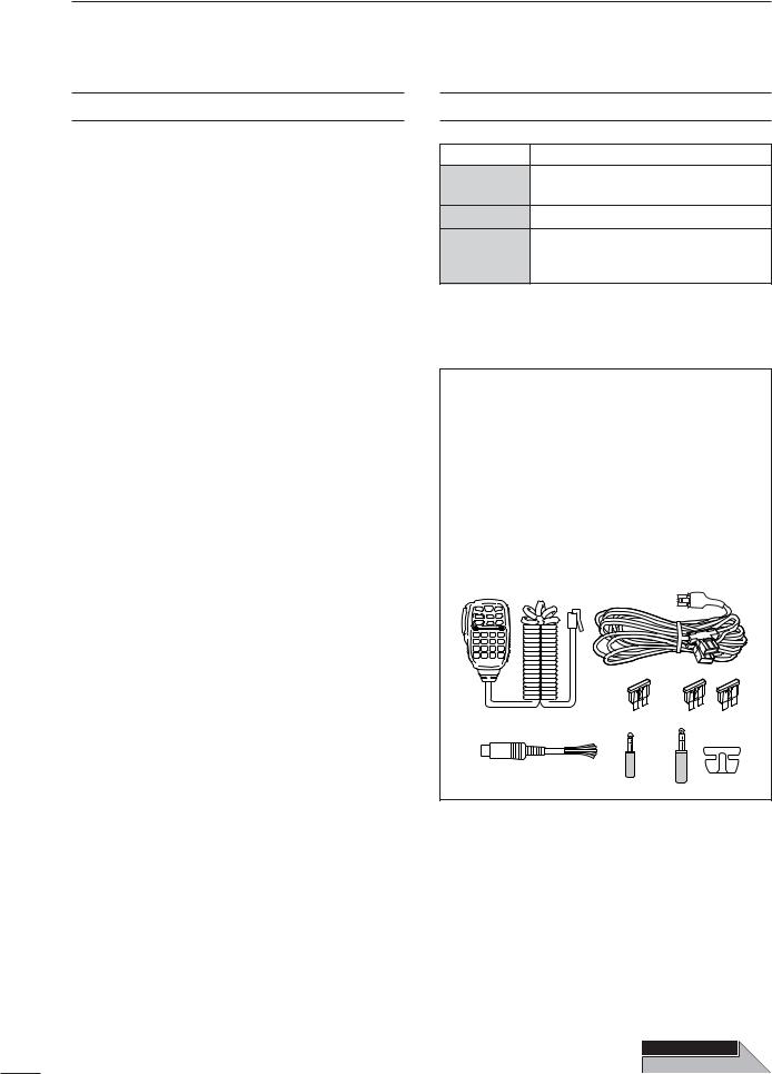
The transceiver comes with the following accessories.
|
|
Qty. |
q Hand microphone (HM-151) ........................... |
1 |
|
w DC power cable (OPC-1457) .......................... |
1 |
|
e Spare fuse (ATC 5 A) ...................................... |
|
1 |
r Spare fuse (ATC 30 A) .................................... |
|
2 |
t ACC cable ........................................................ |
|
1 |
y 3.5 (d) mm plug ................................................ |
|
1 |
u 6.5 (d) mm Electronic keyer plug...................... |
1 |
|
i Microphone hanger........................................... |
|
1 |
q |
w |
|
|
e |
r |
|
t |
y |
u |
i |
Spurious may be received near the following frequencies. These are made in the internal circuit and does not indicate a transceiver malfunction:
52.76497 MHz,
443.03535 MHz
Icom, Icom Inc. and the 
 logo are registered trademarks of Icom Incorporated (Japan) in the United States, the United Kingdom, Germany, France, Spain, Russia and/or other countries.
OPEN
THIS PAGE
i-1

ILLUSTRATIONS
Front panel
|
|
|
|
|
!6 |
@4 |
@3 |
@2 |
@1 |
@0 !9 !8 |
!7 |
q |
|
|
|
|
|
w |
|
|
|
|
|
e |
|
|
|
|
!5 |
|
|
|
|
|
t |
y u i |
o |
!0 !1 !2 |
!4 |
|
|
|
|
!3 |
r |
|
|
|
|
HM-151
z x
c v
b
|
|
|
|
|
|
|
⁄3 |
|
SPCH |
|
TUNER |
|
XFC |
⁄2 |
|||
|
/LOCK |
/CALL |
|
|
⁄1 |
|||
|
|
|
|
|
|
|
||
|
|
|
|
V/M |
|
MW |
⁄0 |
|
|
|
|
|
|
|
|||
|
|
|
|
F-1 |
|
F-2 |
. |
|
|
|
|
|
|
|
|
||
1.8 |
|
3.5 |
|
7 |
|
|
, Mic element |
|
1 |
2 |
3 |
MODE |
m |
||||
|
|
|
||||||
|
|
|
|
|||||
10 |
4 |
14 |
5 |
18 |
6 |
FIL |
n |
|
|
|
|
||||||
|
|
|
|
|||||
21 7 |
24 8 |
28 9 |
GENE |
|
50 |
. |
144 |
430 |
F-INP |
|
0 |
CE |
ENT |
|
The front panel and HM-151’s panel descriptions are descrived between pages 1 to 4, and on page 9, respectively (see the Chapter 1 (Panel description) for more details).
i-2

■Front panel
qAF GAIN CONTROL [AF] (inner control; p. 33)
wRF GAIN CONTROL/SQUELCH CONTROL [RF/SQL] (outer control; p. 35)
ePOWER KEY [PWR] (p. 25)
rFRONT PANEL LATCH (p. 16)
tPASSBAND TUNING/M-ch/RIT CONTROLS [PBT/M-ch/RIT] (pgs. 75, 79, 88, 102, 106)
yTWIN PBT (M-ch/RIT) INDICATOR
(pgs. 75, 79, 88, 102, 106)
uMENU/GROUP KEYS [MENU/GRP] (p. 153)
iTUNER/CALL KEY [TUNER/CALL]
(pgs. 102, 116)
oMULTI-FUNCTION KEYS [F1]/[F2]/[F3]/[F4]
(pgs. 5–8, 153)
!0MANUAL NOTCH KEY [MNF/ADJ] (p. 83)
!1AUTO NOTCH/VOICE RECORDER KEY [ANF/• REC] (pgs. 82, 95)
!2SPCH/LOCK KEY [SPCH/LOCK] (pgs. 34, 37)
!3MICROPHONE CONNECTOR (p. 10)
!4UP/DOWN (BAND) KEYS [Y(BAND)]/[Z(BAND)]
!5MAIN DIAL TENSION LATCH
!6HEADPHONE JACK [PHONES] (p. 18)
!7MAIN DIAL [DIAL]
!8RECEIVE/TRANSMIT INDICATORS [RX]/[TX]
!9TUNING STEP KEY [TS] (pgs. 30–32)
@0NOISE BLANKER KEY [NB/ADJ] (p. 80)
@1NOISE REDUCTION KEY [NR/LEV] (p. 81)
@2FUNCTION DISPLAY (p. 13)
@3PRE AMP/ATTENUATOR KEY [P.AMP/ATT]
(p. 74)
@4MODE KEY [MODE] (p. 34)
■Microphone (HM-151)
zSPCH/LOCK KEY [SPCH/LOCK] (p. 34, 37) xPTT SWITCH [PTT] (p. 37)
cUP/DOWN SWITCHES [Y]/[Z] vTRANSMIT INDICATOR
bKEYPAD (pgs. 28, 29)
nFILTER SELECTION [FIL] (p. 77)
mMODE KEY [MODE] (p. 34)
,POWER INDICATOR
.PROGRAMMABLE FUNCTION KEYS [F-1]/[F-2]
⁄0MEMORY WRITE [MW] (pgs. 103, 104)
⁄1VFO/MEMORY SELECTION [V/M]
(pgs. 27, 102, 109)
⁄2TRANSMIT FREQUENCY CHECK [XFC]
(pgs. 65, 91)
⁄3TUNER/CALL KEY [TUNER/CALL]
(pgs. 102, 116)
i-3

PRECAUTIONS
R WARNING RF EXPOSURE! This device emits Radio Frequency (RF) energy. Extreme caution should be observed when operating this device. If you have any questions regarding RF exposure and safety standards please refer to the Federal Communications Commission Office of Engineering and Technology’s report on Evaluating Compliance with FCC Guidelines for Human Radio Frequency Electromagnetic Fields (OET Bulletin 65).
RWARNING HIGH VOLTAGE! NEVER attach an antenna or internal antenna connector during transmission. This may result in an electrical shock or burn.
R NEVER apply AC to the [DC13.8V] socket on the transceiver rear panel. This could cause a fire or damage the transceiver.
R NEVER apply more than 16 V DC, such as a 24 V battery, to the [DC13.8V] jack on the transceiver rear panel. This could cause a fire or damage the transceiver. RNEVER let metal, wire or other objects touch any internal part or connectors on the rear panel of the transceiver. This may result in an electric shock.
R NEVER connect or use the HM-151 (microphone) with other transceiver. This could cause damage to the
transceiver. The HM-151 is designed for use with the IC7000 ONLY
NEVER expose the transceiver to rain, snow or any liquids.
AVOID using or placing the transceiver in areas with temperatures below –10°C (+14°F) or above +60°C (+140°F). Be aware that temperatures on a vehicle’s dashboard can exceed +80°C (+176°F), resulting in permanent damage to the transceiver if left there for extended periods.
AVOID placing the transceiver in excessively dusty environments or in direct sunlight.
AVOID placing the transceiver against walls or putting anything on top of the transceiver. This will obstruct heat dissipation.
Place unit in a secure place to avoid inadvertent use by children.
During mobile operation, NEVER place the transceiver where air bag deployment may be obstructed.
During mobile operation, DO NOT place the transceiver where hot or cold air blows directly onto it.
During mobile operation, DO NOT operate the transceiver without running the vehicle’s engine. When the transceiver’s power is ON and your vehicle’s engine is OFF, the vehicle’s battery will soon become exhausted.
Make sure the transceiver power is OFF before starting the vehicle. This will avoid possible damage to the transceiver by ignition voltage spikes.
During maritime mobile operation, keep the transceiver and microphone as far away as possible from the magnetic navigation compass to prevent erroneous indications.
BE CAREFUL! The rear panel will become hot when operating the transceiver continuously for long periods.
BE CAREFUL! If a linear amplifier is connected, set the transceiver’s RF output power to less than the linear amplifier’s maximum input level, otherwise, the linear amplifier will be damaged.
Use Icom microphones only (supplied or optional). Other manufacturer’s microphones have different pin assignments, and connection to the IC-7000 may damage the transceiver.
Beat signals may be heard on some frequencies. These will occur as a result of circuit construction.
For U.S.A. only
Caution: Changes or modifications to this transceiver, not expressly approved by Icom Inc., could void your authority to operate this transceiver under FCC regulations.
ii

TABLE OF CONTENTS
IMPORTANT …………………………………………i-1 FOREWORD ………………………………………… i-1 EXPLICIT DEFINITIONS …………………………… i-1 SUPPLIED ACCESSORIES …………………………i-1 ILLUSTRATIONS ……………………………………i-2
■Front panel ……………………………………… i-3
■Microphone (HM-151) ………………………… i-3
PRECAUTIONS ………………………………………ii
TABLE OF CONTENTS …………………………… iii
1PANEL DESCRIPTION ………………… 1–14
■Front panel ………………………………………… 1
■Multi-function keys ……………………………… 5 DMenu M-1 functions …………………………… 5 DMenu M-2 functions …………………………… 5 DMenu M-3 functions …………………………… 5 DMenu S-1 functions …………………………… 7 DMenu S-2 functions …………………………… 7 DMenu S-3 functions …………………………… 8 DMenu G-1 (Scope) functions ………………… 8
■Microphone (HM-151) …………………………… 9 DMicrophone connector ……………………… 10
■Rear panel ……………………………………… 11 DDATA socket …………………………………… 12 DACC socket …………………………………… 12
■Function display ………………………………… 13
2INSTALLATION AND CONNECTIONS … 15–24
■Unpacking ……………………………………… 15
■Selecting a location……………………………… 15
■Grounding………………………………………… 15
■Antennaconnection……………………………… 15
■Installation ……………………………………… 16 DSingle body mounting ………………………… 16 DStand …………………………………………… 16 DFront panel separation ……………………… 16 DFront panel mounting ………………………… 16
■Required connections…………………………… 17
■Advanced connections ………………………… 18
■Power supply connections……………………… 19
■Connecting a DC power supply ……………… 19
■Battery connections …………………………… 19
■External antenna tuners………………………… 20
■Linear amplifier connections …………………… 21
■Connections for CW …………………………… 22
■Connections for RTTY (FSK) ………………… 23 DWhen connecting to [ACC] socket ………… 23 DWhen connecting to [MIC] connector ……… 23
■Connections for packet ………………………… 24 DWhen connecting to [DATA] socket ………… 24 DWhen connecting to [ACC] socket ………… 24 DWhen connecting to [MIC] connector ……… 24
3 BASIC OPERATION ……………………25–38
■When first applying power (CPU resetting)…… 25 DMenu resetting (M-1) ………………………… 25
■Initial settings …………………………………… 25
■VFO description ………………………………… 26
DDifferences between VFO and
memory mode ………………………………… 26
■VFO operation …………………………………… 27 DSelecting VFO A/VFO B ……………………… 27 DVFO equalization……………………………… 27
■Selecting VFO/memory mode ………………… 27
■Selecting an operating band …………………… 28 DUsing the band stacking registers…………… 28
■Frequency setting ……………………………… 29 DTuning with the main dial …………………… 29 DDirect frequency entry
with the microphone’s keypad ……………… 29 DProgrammable tuning step…………………… 30 DSelecting “kHz” step ………………………… 30 DSelecting 1 Hz or 10 Hz step
(SSB/CW/RTTY only) ………………………… 31 D1 MHz quick tuning step
(FM/WFM/AM only) …………………………… 31 D1⁄4 tuning function (CW/RTTY only) ………… 32 DAuto tuning step function …………………… 33 DBand edge warning beep …………………… 33
■Volume setting…………………………………… 33
■Operating mode selection ……………………… 34
■Voice synthesizer function……………………… 34
■Squelch and receive (RF) sensitivity ………… 35
■Meter function …………………………………… 36 DMulti-function meter…………………………… 36
■Lock functions …………………………………… 37 DDial lock function ……………………………… 37 DMicrophone lock function …………………… 37
■Basic transmit operation ……………………… 37 DTransmitting …………………………………… 37 DSetting output power ………………………… 38 DSetting microphone gain……………………… 38
4 RECEIVE AND TRANSMIT …………… 39–71
■Operating SSB…………………………………… 39 DConvenient functions for receive …………… 39 DConvenient functions for transmit …………… 40 DAbout 5 MHz band operation
(USA version only) …………………………… 40
■Operating CW …………………………………… 41 DConvenient functions for receive …………… 42 DConvenient functions for transmit …………… 42 DCW reverse mode …………………………… 43 DCW side tone function………………………… 43 DCW pitch control ……………………………… 44 DElectronic CW keyer ………………………… 45 DMemory keyer send menu …………………… 46 DEditing a keyer memory ……………………… 47 DContest number set mode …………………… 48
1 Number Style ……………………………… 48
2 Count UP Trigger …………………………… 48
3 Present Number …………………………… 48 DKeyer set mode ……………………………… 49 1 Keyer Repeat Time ………………………… 49 2 Dot/Dash Ratio……………………………… 49 3 Rise Time …………………………………… 50
iii

4 Paddle Polarity ……………………………… 50
5 Keyer Type ………………………………… 50
6 MIC U/D Keyer (HM-103) ………………… 50 DPaddle operation
from [MIC] connector ………………………… 50
■Operating RTTY (FSK) ………………………… 51 DConvenient functions for receive …………… 52 DRTTY reverse mode ………………………… 53 DTwin peak filter………………………………… 53 DFunctions for the RTTY decoder indication… 54 DSetting the decoder threshold level ………… 54 DRTTY decode set mode ……………………… 55
1 RTTY Decode USOS ……………………… 55
2 RTTY Decode New Line Code …………… 55 DPre-setting for using RTTY terminal or TNC 56
■Operating AM …………………………………… 57 DConvenient functions for receive …………… 57 DConvenient functions for transmit …………… 58
■Operating FM …………………………………… 59 DConvenient functions for receive …………… 59 DConvenient functions for transmit …………… 59 DTone squelch operation ……………………… 60 DTone scan operation ………………………… 61 DDTCS operation ……………………………… 62
■Repeater operation……………………………… 63 DOne-touch repeater function ………………… 63 DRepeater tone frequency …………………… 64 DTransmit frequency monitor check ………… 65 DAuto repeater function ……………………… 65 DStoring a non standard repeater …………… 66
■1750 Hz tone burst ……………………………… 67
■DTMF memory encoder ………………………… 67 DDTMF send menu …………………………… 67 DProgramming a DTMF code ………………… 68 DDTMF speed…………………………………… 68
■TV channel operation …………………………… 69 DConvenient functions for receive …………… 69 DSkip channel setting ………………………… 70 DChannel frequency adjustment ……………… 71
5 FUNCTIONS FOR RECEIVE……………72–84
■Simple band scope ……………………………… 72 DFix mode ……………………………………… 72 DCenter mode…………………………………… 73 DScope set mode ……………………………… 73 1 Max Hold …………………………………… 74 2 Scope Size ………………………………… 74 3 FAST Sweep………………………………… 74 4 FAST Sweep Sound ……………………… 74
■Preamp and attenuator ………………………… 74
■RIT function ……………………………………… 75
■AGC function …………………………………… 76 DAGC time constant selection ………………… 76 DSetting the AGC time constant ……………… 76
■IF filter selection ………………………………… 77 DIF filter selection ……………………………… 77 DFilter passband width setting
(SSB/CW/RTTY/AM only) …………………… 78
TABLE OF CONTENTS
DIF filter shape (SSB/CW only) ……………… 78
■Twin PBT operation …………………………… 79
■Noise blanker …………………………………… 80 DNoise blanker set mode ……………………… 80 1 NB Level …………………………………… 80 2 NB Width …………………………………… 80
■Noise reduction ………………………………… 81 DNoise reduction set mode …………………… 81
NR Level …………………………………… 81
■Notch function …………………………………… 82 DAuto notch function …………………………… 82 DManual notch function………………………… 83 DManual notch filter set mode ………………… 83
■Voice squelch control function ………………… 84
■Meter peak hold function ……………………… 84
6 FUNCTIONS FOR TRANSMIT …………85–94
■VOX function …………………………………… 85 DAdjusting the VOX function ………………… 85 DVOX set mode ………………………………… 86 1 VOX Gain …………………………………… 86 2 Anti-VOX …………………………………… 86 3 VOX Delay ………………………………… 86
■Transmit filter width setting (SSB only) ……… 86
■Break-in function ………………………………… 87 DSemi break-in operation ……………………… 87 DFull break-in operation ……………………… 87
■∂TX function …………………………………… 88
■Monitor function ………………………………… 89
■Speech compressor …………………………… 89 DCompression level setting …………………… 90
COMP Level ……………………………… 90
■Split frequency operation ……………………… 91
■Quick split function ……………………………… 92 DSplit offset frequency setting ………………… 93 DQuick split setting …………………………… 93
■Measuring SWR…………………………………… 94 DSpot measurement …………………………… 94 DPlot measurement …………………………… 94
7VOICE RECORDER FUNCTIONS ……95–101
■Digital voice recorder …………………………… 95
■Recording a received audio ……………………… 95 DBasic recording ……………………………… 95 DOne-touch voice recording…………………… 96
■Playing the recorded contents …………………… 96
■Erasing the recorded contents…………………… 97
■Recording a message for transmit ……………… 98 DRecording ……………………………………… 98 DConfirming/Erasing the recorded message… 98
■Programming a memory name for transmit …… 99
■Sending a recorded message ………………… 100 DTransmit level setting ……………………… 100
■Voice set mode…………………………………… 101 DVoice set mode ……………………………… 101 1 Auto Monitor ……………………………… 101 2 MIC Memo ………………………………… 101
1
2
3
4
5
6
7
8
9
10
11
12
13
14
15
16
17
18
19
20
iv

TABLE OF CONTENTS
8MEMORY OPERATION ………………102–112
■Memory channels ……………………………… 102
■Memory channel selection …………………… 102
■Memory programming ………………………… 103 DProgramming in VFO mode………………… 103 DProgramming in memory mode …………… 104
■Memory channel list …………………………… 105 DSelecting a memory channel
using the memory channel list……………… 105 DSetting a memory channel
as a select memory ………………………… 106 DSelecting a memory bank ………………… 106 DMemory names ……………………………… 107
■Memory clearing ……………………………… 108 DMemory clearing
using the memory channel list……………… 108
■Frequency transferring………………………… 109 DTransferring in VFO mode ………………… 109 DTransferring in memory mode ……………… 110
■Memo pads……………………………………… 111 DWriting frequencies and operating modes
into memo pads ……………………………… 111 DCalling up a frequency from a memo pad … 112
9 SCAN OPERATION ………………… 113–115
■Scan types ……………………………………… 113
■Preparation……………………………………… 113
■Programmed scan operation ………………… 114
■Memory scan operation ……………………… 114
■Select memory scan operation ……………… 115
■Priority watch …………………………………… 115
10 ANTENNA TUNER OPERATION … 116–117
■Optional AT-180 AUTOMATIC ANTENNA TUNER
operation………………………………………… 116 DTuner operation ……………………………… 116 DManual tuning………………………………… 116
■Optional AH-4 AUTOMATIC ANTENNA TUNER
operation………………………………………… 117 DAH-4 operation ……………………………… 117
11 PACKET OPERATION …………………… 118
■Packet operation ……………………………… 118 DData socket…………………………………… 118 DAdjusting the data speed …………………… 118 DAdjusting the transmit signal output
from the TNC ………………………………… 118
12 CLOCK AND TIMERS ……………… 119–121
■Time set mode ………………………………… 119 DSetting the current year …………………… 120 DSetting the current date …………………… 120 DSetting the current time …………………… 120 DClock2 function activity……………………… 121 DClock2 offset setting ………………………… 121 DAuto power OFF activity …………………… 121
13 SET MODE ………………………… 122–138
■Set mode description ………………………… 122
■Quick set mode ………………………………… 123
RF Power (all modes) ……………………… 123
MIC Gain (SSB/AM/FM modes)…………… 123
SSB TBW (WIDE) L (SSB mode) ………… 123
SSB TBW (WIDE) H (SSB mode) ………… 124
SSB TBW (MID) L (SSB mode) …………… 124
SSB TBW (MID) H (SSB mode) |
………… 124 |
SSB TBW (NAR) L (SSB mode) |
………… 124 |
SSB TBW (NAR) H (SSB mode) ………… 124
Key Speed (CW mode) …………………… 124
CW Pitch (CW mode) ……………………… 124
Side Tone Level (CW mode) ……………… 125
Side Tone Level Limit (CW mode)………… 125
Twin Peak Filter (RTTY mode) …………… 125
RTTY Mark Frequency (RTTY mode) …… 125
RTTY Shift Width (RTTY mode) ………… 125
RTTY Keying Polarity (RTTY mode) ……… 125
■Display set mode ……………………………… 126 1 Contrast (LCD)……………………………… 126 2 Bright (LCD) ………………………………… 126 3 LCD Unit Bright …………………………… 126 4 LCD Flicker ………………………………… 126 5 Backlight (Switches) ……………………… 126 6 Display Type………………………………… 126 7 Display Font Type ………………………… 127
8 Display Font Size ………………………… 127
9 Meter Peak Hold …………………………… 127
10 Filter Popup (PBT) ………………………… 127
11 Filter Popup (FIL)…………………………… 127
12 1 Hz Mode Popup ………………………… 127
13 Scope CENTER/FIX Popup ……………… 127
14 TV Popup (CH Up/Down) ………………… 128
15 TV Popup (P.AMP/ATT) …………………… 128
16 Voice TX Name Display …………………… 128
17 Keyer Memory Display …………………… 128
18 DTMF Memory Display …………………… 128
19 External Display …………………………… 128
20 Opening Message ………………………… 128
21 My Call ……………………………………… 129
22 Power ON Check…………………………… 129
■Miscellaneous (others) set mode …………… 130 1 Monitor ……………………………………… 130 2 Monitor Level ……………………………… 130 3 Beep (Confirmation) ……………………… 130 4 Beep (Band edge) ………………………… 130 5 Beep Level ………………………………… 130 6 Beep Level Limit …………………………… 130
7 RF/SQL Control …………………………… 131
8 Quick SPLIT ………………………………… 131
9 SPLIT Offset………………………………… 131
10 SPLIT LOCK………………………………… 131
11 DUP Offset HF ……………………………… 131
12 DUP Offset 50M …………………………… 131
13 DUP Offset 144M ………………………… 131
14 DUP Offset 430M ………………………… 131
15 One Touch Repeater ……………………… 132
v

16 Auto Repeater ……………………………… 132
17 Tuner (Auto Start) ………………………… 132
18 Tuner (PTT start) …………………………… 133
19 [TUNER] Switch …………………………… 133
20 VSEND Select ……………………………… 133
21 SPEECH level ……………………………… 133
22 SPEECH Language ……………………… 133
23 SPEECH Speed …………………………… 133
24 SPEECH S-Level ………………………… 134
25 SPEECH [MODE] Switch ………………… 134
26 Memopad Numbers ……………………… 134
27 SCAN Speed ……………………………… 134
28 SCAN Resume …………………………… 134
29 MAIN DIAL Auto TS ……………………… 134
30 HM-151 [F-1] ……………………………… 135
31 HM-151 [F-2] ……………………………… 135
32 MIC Up/Down Speed ……………………… 135
33 Quick RIT/∂TX Clear ……………………… 135
34 SSB/CW Synchronous Tuning …………… 135
35 CW Normal Side …………………………… 136
36 VOICE 1st Menu ………………………… 136
37 KEYER 1st Menu ………………………… 136
38 DTMF 1st Menu …………………………… 136
39 Mode Select (SSB) ………………………… 136
40 Mode Select (CW) ………………………… 136
41 Mode Select (RTTY) ……………………… 136
42 Mode Select (AM) ………………………… 137
43 Mode Select (FM) ………………………… 137
44 Mode Select (WFM) ……………………… 137
45 External Keypad (VOICE) ………………… 137
46 External Keypad (KEYER)………………… 137
47 Front Keypad Type ………………………… 138
48 CI-V Baud Rate …………………………… 138
49 CI-V Address ……………………………… 138
50 CI-V Transceive …………………………… 138
51 REF Adjust ………………………………… 138
14 MAINTENANCE ………………………… 139
■Fuse replacement……………………………… 139
■Memory backup………………………………… 139
■Cleaning ………………………………………… 139
15 TROUBLESHOOTING …………… 140–141
16OPTIONAL UNITS SETTING ……… 142–143
■MB-106 CARRYING HANDLE …………………… 142
■AT-180 internal switch description …………… 143
17CONTROL COMMAND …………… 144–148
■Remote jack (CI-V) information ……………… 144 DCI-V connection example …………………… 144 DData format …………………………………… 144 DCommand table ……………………………… 144 DTo send/read memory contents …………… 148 DBand stacking register ……………………… 148 DCodes for memory keyer contents ………… 148 DCharacter’s code for my call ……………… 149
TABLE OF CONTENTS
DCodes for memory name contents ………… 149 |
1 |
|
DSplit/Duplex frequency setting……………… 149 |
||
DRepeater tone/tone squelch frequency |
|
|
2 |
||
setting ………………………………………… 149 |
||
DDTCS code and polarity setting …………… 149 |
|
|
3 |
||
18 SPECIFICATIONS …………………………150 |
||
4 |
||
■General ………………………………………… 150 |
■Transmitter……………………………………… 150
■Receiver ………………………………………… 150 |
5 |
|
|
||
19 OPTIONS …………………………… 151–152 |
|
|
|
||
6 |
||
20 MENU GUIDE ………………………153–154 |
||
|
||
7 |
||
21 ABOUT CE ………………………… 155–156 |
||
|
||
|
8 |
|
|
|
|
|
9 |
|
|
|
|
|
10 |
|
|
|
|
|
11 |
|
|
|
|
|
12 |
|
|
|
|
|
13 |
|
|
|
|
|
14 |
|
|
|
|
|
15 |
|
|
|
|
|
16 |
|
|
|
|
|
17 |
|
|
|
|
|
18 |
|
|
|
|
|
19 |
|
|
|
|
|
20 |
|
|
|
vi
1PANEL DESCRIPTION
■Front panel
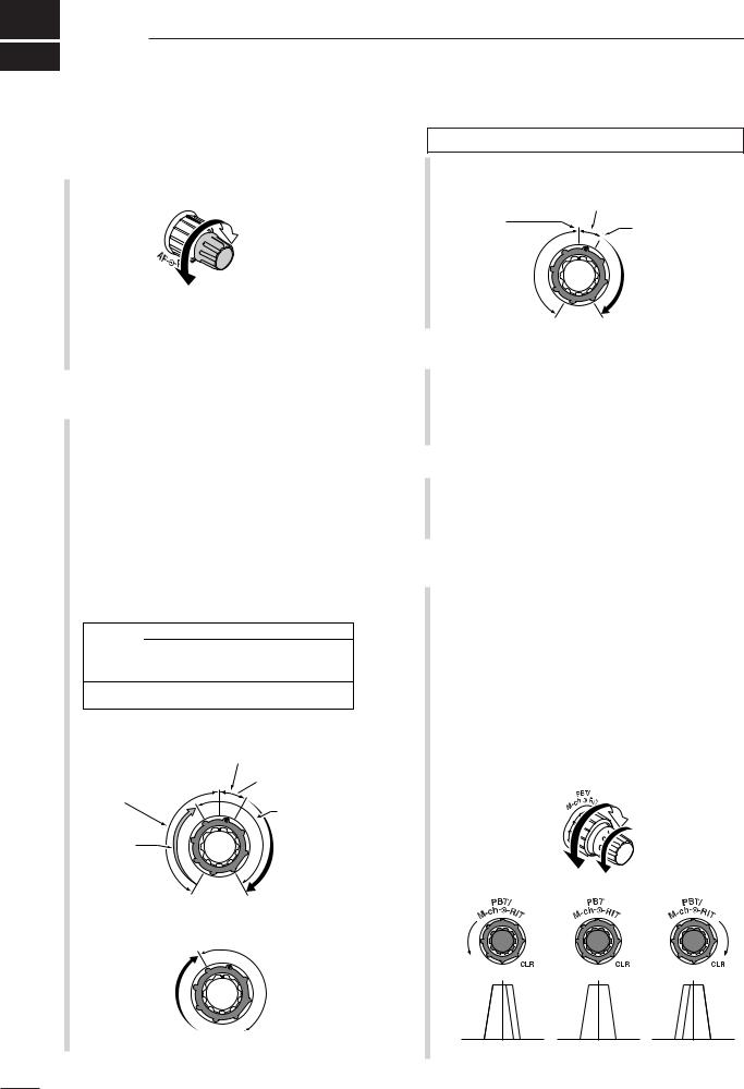
qAF GAIN CONTROL [AF(SET)] (inner control; p. 33)
Rotate to vary the audio output level from the speaker or headphones.
Audio output increases
Audio outut decreases
Push momentarily to enter the set mode menu.
•Push again to exit the set mode menu.
Push and hold for 1 sec. to toggle between the frequency display mode or TV mode.
wRF GAIN CONTROL/SQUELCH CONTROL [RF/SQL] (outer control; p. 35)
Adjusts the RF gain and squelch threshold level. The squelch, when closed, mutes the speaker or headphones when no signal is received, reducing noise.
•The squelch is particularly effective for FM and WFM modes. It is also available in other modes.
•12 to 1 o’clock position is recommended for any setting of the [RF/SQL] control.
•The control can be set to ‘Auto’ (RF gain control in SSB, CW and RTTY; squelch control in AM, FM and WFM) or squelch control (RF gain is fixed at maximum) in the miscellaneous (others) set mode as follows. (p. 131)
MODE |
SET MODE SELECTION |
|||
Auto |
SQL |
RF + SQL |
||
|
||||
SSB, CW |
RF GAIN |
SQL |
RF + SQL |
|
RTTY |
||||
|
|
|
||
AM, FM |
SQL |
SQL |
RF + SQL |
|
WFM |
||||
|
|
|
||
•When functioning as RF gain/squelch control
|
Noise squelch (WFM/FM modes) |
Squelch is |
Recommended level |
|
|
open. |
Maximum |
|
|
|
RF gain |
RF gain |
|
adjustable |
S-meter shows |
range |
squelch level |
•When functioning as RF gain control
(Squelch is fixed open; SSB, CW, RTTY only)
Adjustable range
Minimum RF gain  Maximum RF gain
See the illustration of the Front panel on page i-2.
•When functioning as squelch control
(RF gain is fixed at maximum.)
Noise squelch |
Noise squelch (FM/WFM modes) |
||
|
|
||
threshold |
|
S-meter squelch |
|
(FM/WFM modes) |
|||
threshold |
|||
|
|
||
Squelch is |
|
S-meter |
|
|
squelch |
||
open. |
|
||
|
|
||
Lowest threshold |
Highest threshold |
||
ePOWER KEY [PWR] (p. 25)
While transceiver’s power is OFF, push to turn the power ON.
•Turn the DC power supply ON in advance.
While transceiver’s power is ON, push and hold for 1 sec. to turn the power OFF.
rFRONT PANEL LATCH (p. 16)
Pull away from the transceiver (towards yourself when looking at the front of the transceiver) to detach the front panel from the main body of the transceiver.
tPASSBAND TUNING/M-ch/RIT CONTROLS [PBT/M-ch/RIT]
Push inner control to toggle the twin Passband Tuning (PBT) or memory channel/RIT function ON and OFF.
While Twin PBT is selected (p. 79):
●Adjusts the receiver’s DSP filter passband width.
•Passband width and shift frequency are displayed on the LCD.
•The default variable range is half of the IF filter passband width. 25 Hz step is available.
●Push and hold inner control for 1 sec. to return the PBT to default settings.
PBT1
 PBT2
PBT2
– |
+ |
High cut |
Center |
Low cut |
1
What is the PBT control?
PBT electronically narrows the IF passband width to reject interference. This transceiver uses DSP to implement PBT.
While M-ch/RIT is selected:
●Rotate the inner control to select a memory channel number (p. 102).
●Push inner control for 1 sec. to turn the RIT/∂TX mode ON (pgs. 75, 88).
•Push [Z(MENU/GRP)] to exit the RIT/∂TX mode.
●While the RIT/∂TX mode is OFF:
Rotates outer control to select a memory bank (p. 106).
●While the RIT/∂TX is ON:
Rotate outer control to shift the receive or transmit frequency (pgs. 75, 88).
•“ ” or “
 ” indicators appear when the RIT or ∂TX function is activate, respectively.
•The shift frequency range is ± 9.999 kHz in 1 Hz steps (or ±9.99 kHz in 10 Hz steps).
|
|
RIT |
|
|
|
M-ch |
|
|
M-ch |
|
RIT |
Channel |
Channel |
Frequency |
Frequency |
decreases |
increases |
decreases |
increases |
•When the RIT or ∂TX function is ON, push and hold [F-1 RIT] or [F-2 ∂TX] for 1 sec. to add or subtract the frequency shift to the display frequency.
What is the RIT function?
RIT (Receiver Incremental Tuning) shifts the receive frequency without shifting the transmit frequency.
This is useful for fine tuning for stations calling you off frequency or when you prefer to listen to slightly differentsounding voice characteristics, etc.
What is the ∂TX function?
The ∂TX shifts the transmit frequency without shifting the receive frequency. This is useful for simple split frequency operation in CW, etc.
PANEL DESCRIPTION |
1 |
|
yTWIN PBT (M-ch/RIT) INDICATOR |
|
|
|
1 |
|
(pgs. 75, 79, 88, 102) |
|
Indicates the status of [PBT/M-ch/RIT] (t) activates as the Twin PBT function or memory channel/RIT control.
•Indicator is green when the Twin PBT is selected. •Indicator is off when the M-ch/RIT is selected. •Indicator is orange when the RIT or ∂TX function is activate.
uMENU/GROUP KEYS [MENU/GRP] (p. 153)
Push either key one or more times to select menus within a menu group (M, S or G (Graphic)).
Push and hold for 1 sec. to select one of the three menu groups: M-1 to M-3, S-1 to S-3 and G-1 (Scope) to G-3 (SWR meter).
iTUNER/CALL KEY [TUNER/CALL]
During HF/50 MHz operation (p. 116):
●Push momentarily to toggle the automatic antenna tuner function ON and OFF.
•An optional antenna tuner must be connected. •“ ” indicator appears when the tuner is ON.
●Push and hold for 2 sec. to manually tune the antenna.
•An optional antenna tuner must be connected. •“ ” indicator appears when the tuner is ON.
During 144/430 MHz operation (p. 102):
Push momentarily to select the call channel (or return to the previous channel/frequency when the call channel is already selected).
•“C1” is the 144 MHz call channel and “C2” is the 430 MHz call channel.
oMULTI-FUNCTION KEYS [F-1]/[F-2]/[F-3]/[F-4]
Push to select the function indicated in the LCD display above these keys. (pgs. 5–8, 153)
•Functions vary depending on the active menu.
Functions appear
See the illustration of the Front panel on page i-2.
2
1PANEL DESCRIPTION
!0MANUAL NOTCH KEY [MNF/ADJ] (p. 83)
Push momentarily to turn the manual notch function ON and OFF in SSB, CW and AM modes.
•“ ” appears on the display when the function is activated.
Push and hold for 1 sec. to enter the manual notch filter set mode.
What is the notch function?
The notch function is a narrow DSP filter that removes interfering tones from CW or AM signals while preserving the desired signal's frequency response.
!1AUTO NOTCH/VOICE RECORDER KEY [ANF/• REC]
Push momentarily to turn the auto notch function (ANF) ON and OFF in SSB, AM, FM modes. (p. 82)
•“ ” appears on the display when the function is activated.
Push and hold for 1 sec. to record the received signal’s audio. (p. 95)
!2SPCH/LOCK KEY [SPCH/LOCK]
Push momentarily to have the frequency, etc. announced by the speech synthesizer. (p. 34)
•The parameters to be announced can be selected in the miscellaneous (others) set mode. (p. 134)
Push and hold for 1 sec. to toggle the dial lock function ON and OFF. (p. 37)
•The dial lock function electronically locks the main dial.
•“  ” appears while the dial lock function is activate.
!3MICROPHONE CONNECTOR (p. 10) Modular-type microphone connector—Accepts the supplied microphone (HM-151).
•The optional OPC-589 can be used to connect an 8-pin microphone such as the SM-20, if desired.
•A microphone connector is also available on the rear panel. DO NOT connect 2 microphones simultaneously.
!4UP/DOWN (BAND) KEYS [Y(BAND)]/[Z(BAND)]
Push momentarily to select a frequency band or TV channel.
Push and hold [Y(BAND)] for 1 sec. to toggle the simple band scope display ON and OFF.
Push and hold [Z(BAND)] for 1 sec. to toggle the multi-function meter display ON and OFF.
!5MAIN DIAL TENSION LATCH
Selects the main dial drag.
•Three positions are available. Upper setting turns on clicks as the dial is turned..
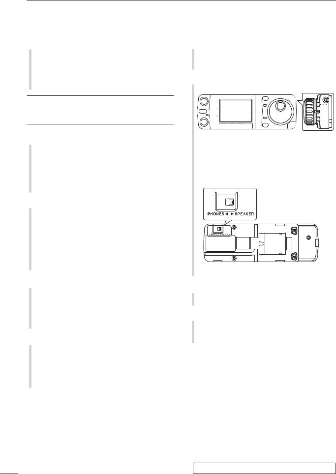
!6HEADPHONE JACK [PHONES] (p. 18) Accepts headphones with 8–16 impedance.
•When headphones are connected, no receive audio comes from the speaker.
•When the PHONES/SPEAKER switch on the back of the front panel is set to the [SPEAKER] position, an external
speaker can be used instead of headphones. This is convenient for mobile or outdoor operation.
Back of the front panel
!7MAIN DIAL [DIAL]
Changes the displayed frequency and selects values for selected set mode items, etc.
!8RECEIVE/TRANSMIT INDICATORS [RX]/[TX]
[RX]: Lights green in receive mode and when squelch is open.
[TX]: Lights red while transmitting.
See the illustration of the Front panel on page i-2.
3
!9TUNING STEP KEY [TS] (pgs. 30–32)
While in SSB/CW/RTTY modes, push momentarily to turn the programmable tuning step ON and OFF. While in AM/FM/WFM modes, push momentarily to toggle the programmable tuning step and 1 MHz quick tuning step.
•While the programmable tuning step indicator is displayed, the frequency can be changed in programmed kHz steps.
Programmable tuning step indicator
•0.01 (AM/FM/WFM mode only), 0.1, 1, 5, 9, 10, 12.5, 20, 25 and 100 kHz tuning steps are available.
•A MHz quick tuning step is only available in AM, FM and WFM modes.
While programmable tuning steps are OFF, turns the 1 Hz step ON and OFF when pushed and held for 1 sec.
•1 and 10 Hz steps are only available in SSB, CW and RTTY modes.
•1 Hz indication appears, and the frequency can be changed in 1 Hz steps.
While the programmable tuning step is ON, enters the tuning step selection mode when pushed and held for 1 sec.
@0NOISE BLANKER KEY [NB/ADJ] (p. 80)
Push momentarily to turn the noise blanker ON and OFF. The noise blanker reduces pulse-type noise such as that generated by automobile ignition systems. This function does not work on nonpulse noise or in WFM mode.
•“ ” appears when the noise blanker is ON.
Push and hold for 1 sec. to enter the noise blanker set mode.
@1NOISE REDUCTION KEY [NR/LEV] (p. 81)
Push momentarily to turn DSP noise reduction ON and OFF.
•“ ” appears on the display when the function is activated.
Push and hold for 1 sec. to enter the DSP noise reduction level.
|
|
PANEL DESCRIPTION |
1 |
|
@2FUNCTION DISPLAY |
|
|
||
|
1 |
|||
|
|
Shows the operating frequency, function key menus, |
||
|
|
|||
|
|
simple band scope display, selected memory chan- |
|
|
|
|
nel, receiving TV channel, etc. See p. 13 for details. |
|
|
@3PRE AMP/ATTENUATOR KEY [P.AMP/ATT]
(p. 74)
Push momentarily to turn the preamp ON or OFF.
•“ ” indicator appears when the preamp is activated.
Push and hold for 1 sec. to turn the 12 dB attenuator ON; push momentarily to turn the attenuator OFF.
•“ ” indicator appears when the attenuator is activated.
What is the preamp?
The preamp amplifies signals in the receiver front end (input) circuit to improve the S/N ratio and sensitivity. Turn ON ‘P.AMP’ when receiving weak signals.
What is the attenuator?
The attenuator prevents a strong undesired signal near the desired frequency or near your location, such as from a broadcast station, from causing distortion or spurious signals.
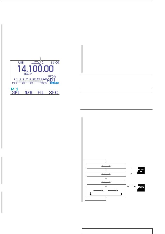
@4MODE KEY [MODE] (p. 34)
Push momentarily to cycle through the operating modes:
USB/LSB CW/CW-R RTTY/RTTY-R AM/FM/WFM
Push and hold for 1 sec. to toggle the following operating modes:
USB LSB CW CW-R
RTTY RTTY-R |
|
|
AM FM |
WFM |
AM, etc |
OPERATING MODE SELECTION |
|
|
USB |
LSB |
Push |
|
||
CW |
CW-R |
momentarily |
|
|
|
RTTY |
RTTY-R |
Push and hold |
AM |
FM |
WFM |
|
|
for 1 sec. |
See the illustration of the Front panel on page i-2.
4
1PANEL DESCRIPTION
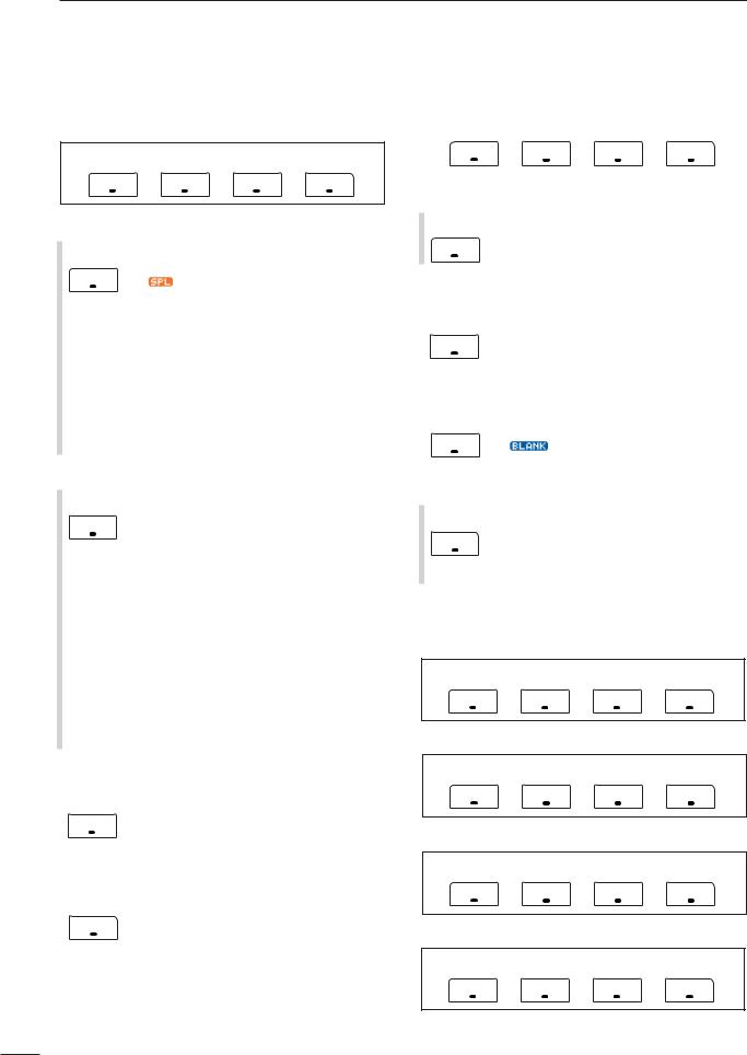
■Multi-function keys
DMenu M-1 functions
SPL |
A/B |
FIL |
XFC |
F-1 |
F-2 |
F-3 |
F-4 |
SPLIT OPERATION
SPL Push momentarily to toggle the split function ON and OFF. (p. 91)
F-1 |
•“ |
” and transmit frequency appear when |
the split function is ON.
Push and hold for 1 sec. to turn the quick split function ON. (p. 92)
•The offset frequency must be programmed in advance using the miscellaneous (others) set mode. (p. 131)
•The offset frequency is shifted from the displayed frequency.
•The quick split function can be turned OFF in the miscellaneous (others) set mode. (p. 131)
VFO A/B SELECTION
A/B |
Push momentarily to exchange the trans- |
mit VFO and receive VFO contents. (p. |
|
F-2 |
27) |
|
Push momentarily to toggle the transmis- |
|
sion VFO and reception VFO during split |
|
operation. (p. 91) |
|
Push momentarily to toggle the transmit |
|
and receive frequencies (and modes) of |
|
memory channels when the split function |
|
is turned ON. |
|
Push and hold for 1 sec. to equalize the |
|
frequency and operating mode of the two |
|
VFO’s. |
|
•The lower indicated frequency and operating |
|
mode are equalized to the upper (indicated) |
|
VFO frequency and operating mode. |
FILTER SELECTION (p. 77)
|
FIL |
Push momentarily to select one of three |
|
F-3 |
IF filter settings. |
|
Push and hold for 1 sec. to enter the filter |
|
|
|
set mode. |
TRANSMIT FREQUENCY CHECK (pgs. 65, 91) |
||
|
XFC |
Monitors the transmit frequency when |
|
||
|
F-4 |
pushed and held. |
|
•While pushing this key, the transmit fre- |
|
|
|
quency can be changed with [DIAL]. |
|
|
|
D Menu M-2 functions
MEM |
MW |
MCL |
V/M |
F-1 |
F-2 |
F-3 |
F-4 |
|
|
|
|
MEMORY MENU (p. 105) |
|
|
|
MEM |
Push momentarily to indicate the memory |
||
frequency and modes. |
|
||
F-1 •Memory list indication is available.
MEMORY WRITE (pgs. 103, 104)
|
MW |
Push and hold for 1 sec. to store the se- |
|
|
lected readout frequency and operating |
||
|
F-2 |
||
|
mode into the displayed memory channel. |
||
|
|
||
MEMORY CLEAR (p. 108) |
|||
|
MCL |
Push and hold for 1 sec. to clear the se- |
|
|
|||
|
|
lected memory channel contents. |
|
|
F-3 |
•“ |
” appears. |
|
|
|
|
VFO/MEMORY SELECTION
Push momentarily to toggle VFO and V/M memory modes. (pgs. 27, 102)
F-4 Push and hold for 1 sec. to transfer the selected memory channel to the currently displayed VFO. (p. 109)
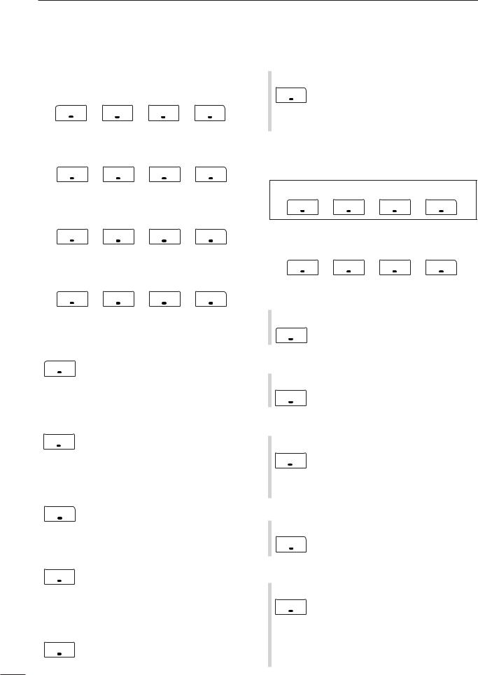
D Menu M-3 functions
DURING SSB OPERATION:
VOX |
COM |
AGC |
TBW |
F-1 |
F-2 |
F-3 |
F-4 |
DURING CW OPERATION:
BRK |
1/4 |
AGC |
|
F-1 |
F-2 |
F-3 |
F-4 |
DURING RTTY OPERATION:
1/4 AGC
F-1 |
F-2 |
F-3 |
F-4 |
DURING AM OPERATION:
VOX AGC
F-1 |
F-2 |
F-3 |
F-4 |
5

DURING FM/WFM OPERATIONS:
VOX |
DUP |
TON |
9600 |
|
F-1 |
F-2 |
F-3 |
F-4 |
|
|
|
|
||
VOX FUNCTION (p. 85) |
|
|
||
VOX |
Push momentarily to toggle the VOX func- |
|||
tion ON and OFF. |
|
|||
F-1 |
|
•“ ” appears when the VOX function is |
||
ON.
Push and hold for 1 sec. to enter the VOX set mode.
•The VOX gain, ANTI-VOX, VOX delay and VOX gain can be set in VOX set mode.
What is the VOX function?
The VOX function (voice operated transmission) activates the transmitter when you speak into the microphone; then, automatically returns to receive when you stop speaking.
SPEECH COMPRESSOR (p. 89)
COM Push momentarily to toggle the speech compressor ON and OFF.
F-2 |
•“ |
” appears when the speech compres- |
sor is ON.
Push and hold for 1 sec. to enter the compression level set mode.
•Speech compression can be adjusted in compression level set mode.
AGC (p. 76)
AGC Push to change the time constant of the AGC circuit.
F-3 •“ ,” “
,” “ ” or “
 ” appears when the fast time constant, middle time constant or slow time constant is selected, respectively.
Push and hold for 1 sec. to enter the AGC set mode.
•“ ” (OFF) can be selected.
TBW (p. 86)
TBW |
Push momentarily to indicate the selected |
|
TX filter width. |
||
F-4 |
•The popup indicator appears. |
|
|
Push and hold for 1 sec. to toggle the TX |
|
|
filter width between narrow, middle or |
|
|
wide. |
|
|
•The following filters are specified as the de- |
|
|
fault. Each filter width can be set in the quick |
|
|
set mode. (pgs. 123, 124) |
|
|
WIDE |
: 100 Hz to 2900 Hz |
|
MID |
: 300 Hz to 2700 Hz |
|
NAR |
: 500 Hz to 2500 Hz |
|
|
PANEL DESCRIPTION |
1 |
|
||
BREAK-IN FUNCTION (p. 87) |
|
|
||||
|
1 |
|||||
BRK Push momentarily to select semi-break-in, |
||||||
|
||||||
F-1 |
full break-in (QSK) and break-in OFF. |
|
|
|||
•“ |
” or “ |
” appears when selecting |
|
|||
semi break-in or full break-in, respectively. •An external switch, such as a foot switch, must be connected to the ACC socket (pin 3, pin 7 or RTTY SEND—see p. 23) if break-in is turned OFF.
Push and hold for 1 sec. to enter the break-in delay time set mode.
What is the break-in function?
Full break-in (QSK) activates the receiver between transmitted dots and dashes. This is useful when operating in nets, or during DX pile-ups and during contests, when “fast responses” are common.
1/4 FUNCTION
1/4 |
Push to toggle the 1/4-speed tuning func- |
F-2 |
tion ON and OFF in CW and RTTY |
modes. |
•When the 1⁄4 function is ON, “ ” appears and fine tuning can be used.
DUPLEX FUNCTION (p. 63)
DUP Push to select the duplex transmit offset direction or turn the function OFF.
F-2 Push and hold for 1 sec. to turn the onetouch repeater function ON/OFF.
FM TONE OPERATION
TON Push momentarily to set the subaudible |
|
F-3 |
tone encoder for repeater use, tone |
squelch function, DTCS and OFF. |
|
•“ ” appears when the repeater tone function is ON. (p. 63)
•“ ” appears when the tone squelch function is ON. (p. 60)
•“ ” appears when the DTCS squelch function is ON. (p. 62)
Push and hold for 1 sec. to enter the tone frequency or DTCS code set mode. (pgs. 60, 62)
•Tone scan function is also available. (p. 61)
Push and hold to transmit a 1750 Hz tone when pushing and holding [PTT]. (p. 67)
9600 MODE
9600 |
Push to turn the 9600 bps data transmis- |
F-4 |
sion mode ON and OFF. (p. 118) |
|
6
1PANEL DESCRIPTION
DMenu S-1 functions
DURING SSB/AM OPERATION:
|
VO |
|
MET |
VSC |
|
|
F-1 |
F-2 |
F-3 |
F-4 |
|
|
|
|
|
|
|
DURING CW OPERATION: |
|
|
|
||
|
|
|
|
|
|
|
VO |
KEY |
MET |
VSC |
|
|
F-1 |
F-2 |
F-3 |
F-4 |
|
|
|
|
|
||
DURING RTTY OPERATION: |
|
|
|||
|
|
|
|
|
|
|
VO |
DEC |
MET |
VSC |
|
|
F-1 |
F-2 |
F-3 |
F-4 |
|
|
|
|
|
||
DURING FM/WFM OPERATIONS: |
|
|
|||
|
|
|
|
|
|
|
VO |
DTM |
MET |
VSC |
|
|
F-1 |
F-2 |
F-3 |
F-4 |
|
|
|
|
|
|
|
VO (p. 95) |
|
|
|
|
|
|
VO |
Push to enter the voice recorder mode. |
|||
|
|||||
|
•The voice TX/RX menu or voice root menu |
||||
|
|
||||
|
F-1 |
appears depending on the “VOICE 1st |
|||
|
|
Menu” setting in the miscellaneous (others) |
|||
|
|
set mode. (p. 136) |
|
|
|
METER SELECTION (p. 36) |
|
|
|||
|
MET |
Push to select the type of metering dis- |
|||
|
|||||
|
played (during transmit) on the display. |
||||
|
F-3 |
•Power, SWR, ALC or COMP metering can be |
|||
|
|
selected. |
|
|
|
|
|
•Only an S-meter is available during receive. |
|||
VOICE SQUELCH CONTROL (p. 84) |
|
|
|||
|
VSC |
Push to toggle the voice squelch control |
|||
|
|||||
|
F-4 |
function ON and OFF. |
|
|
|
|
|
|
|
|
|
|
|
|
|
||
KEYER OPERATION (p. 45) |
|
|
|||
|
KEY |
Push to enter the memory keyer mode. |
|||
|
|||||
|
F-2 |
•The keyer send menu or keyer root menu ap- |
|||
|
pears depending on the |
“KEYER 1st |
|||
|
|
Menu” setting in the miscellaneous (others) |
|||
|
|
set mode.(p. 136) |
|
|
|
RTTY DECODER FUNCTION (p. 54) |
|
|
|||
|
DEC |
Push to toggle the RTTY decoder display |
|||
|
|||||
|
F-2 |
ON and OFF. |
|
|
|
|
•RTTY decoder screen appears. |
||||
|
|
|
|
|
|
DTMF OPERATION
DTM |
Push to enter DTMF memory mode. |
F-4 |
(p. 67) |
•The DTMF send menu or DTMF root menu |
|
|
appears depending on the “DTMF 1st |
|
Menu” setting in the miscellaneous (others) |
|
set mode. (p. 136) |
D Menu S-2 functions
DURING VFO MODE:
SCN |
PRI |
V/M |
VSC |
F-1 |
F-2 |
F-3 |
F-4 |
DURING MEMORY MODE:
SCN |
SEL |
V/M |
VSC |
F-1 |
F-2 |
F-3 |
F-4 |
|
|
|
|
SCAN (pgs. 113–115)
SCN Push momentarily to start or stop the
scan function.
F-1
PRIORITY WATCH (p. 115)
PRI Push to start or stop priority watch.
F-2
VFO/MEMORY SELECTION
V/M Push momentarily to toggle VFO and memory modes. (pgs. 27, 102)
F-3 Push and hold for 1 sec. to transfer the frequency and operating mode in the selected memory channel to the currently displayed VFO. (p. 109)
VOICE SQUELCH CONTROL (p. 84)
VSC |
Push to toggle the voice squelch control |
F-4 |
function ON and OFF. |
|
SELECT SCAN
SEL Push momentarily to toggle the select |
|
F-2 |
scan settings ON and OFF for the se- |
lected memory channel. (pgs. 106, 115) |
|
Push and hold for 2 sec. to clear all select scan setting. (p. 115)
While scanning, push to toggle the se-
lected memory scan ON and OFF. (p. 115)
7

D Menu S-3 functions
MW |
MPW |
MPR |
|
F-1 |
F-2 |
F-3 |
F-4 |
|
|
|
|
MEMORY WRITE (pgs. 103, 104)
Push and hold for 1 sec. to store the dis- MW played VFO frequency and operating F-1 mode into the selected memory channel.
MEMO PAD WRITE (p. 111)
|
MPW |
Push to store the displayed VFO fre- |
|
quency and operating mode into a memo |
|
|
F-2 |
pad. |
|
|
|
MEMO PAD READ (p. 112) |
||
|
MPR |
Push to call up a memo pad. |
|
||
|
F-3 |
|
|
|
|
What is the memo pad function?
The memo pad function stores the frequency and operating mode for easy recall. The memo pads are separate from the usual memory channels. The default number of memo pads is 5, however, this can be increased to 10 in the miscellaneous (others) set mode, if desired. (p. 134)
PANEL DESCRIPTION |
1 |
D Menu G-1 (Scope) functions |
|
|
|
||
|
|
1 |
|||
|
|
|
|
|
|
SPN |
HLD |
FIX |
SPD |
|
|
|
|
||||
F-1 |
F-2 |
F-3 |
F-4 |
|
|
|
|
|
|
|
|
SWEEP STEPS (pgs. 72, 73)
SPN Push momentarily to change the sweep step size.
F-1 |
•Available steps are ±10, 25, 50, 100 and 250 |
|
kHz. |
Push and hold for 1 sec. to change the sweep steps to ±10 kHz.
PEAK HOLD (pgs. 72, 73)
HLD Push to freeze the current simple band scope display.
F-2 |
•“H” indicator appears while the function is in |
use.
Push and hold for 1 sec. to clear the peak levels.
•Peak levels are displayed in the background on the simple band scope display. The peak hold function can be disabled in the scope set mode. (p. 73)
FIX/CENTER SELECTION (pgs. 72, 73)
FIX Push to toggle the simple band scope fix mode and center mode.
F-3 •Fix mode:
Rotating [DIAL] leaves the marker centered.
•Center mode:
Rotating [DIAL] moves the edge frequencies.
While fix mode operation, push and hold for 1 sec. to set the displayed frequency to that of the marker.
SWEEP SPEED
SPD Push momentarily to change the sweep
speed between Fast and Slow. (pgs. 72,
F-4 73)
Push and hold for 1 sec. to enter the scope set mode. (p. 73)
8

1PANEL DESCRIPTION
■Microphone (HM-151)
zSPCH/LOCK KEY [SPCH/LOCK]
Push momentarily to have the frequency, etc. announced by the speech synthesizer. (p. 34)
•The parameters to be announced can be selected in the miscellaneous (others) set mode. (p. 134)
Push and hold for 1 sec. to toggle the microphone lock function ON and OFF. (p. 37)
xPTT SWITCH [PTT] (p. 37)
Push and hold to transmit; release to receive.
cUP/DOWN SWITCHES [Y]/[Z]
Change the operating frequency.
•Push and hold to change the frequency repeatedly. •Tuning step size is 50 Hz if no TS indicator is displayed.
vTRANSMIT INDICATOR
Lights red while transmitting.
bKEYPAD
Pushing a key selects the operating band.
•[(GENE)•] selects the general coverage band.
Pushing the same key 2 or 3 times calls up other stacked frequencies in the band. (p. 28)
•Icom’s triple band stacking register memorizes 3 frequencies in each band.
After pushing [(F-INP)ENT], enter a numeric frequency, followed by pressing [(F-INP)ENT]
again. (p. 29)
•e.g. to enter 14.195 MHz, push [(F-INP)ENT] [1] [4]
[•][1] [9] [5] [(F-INP)ENT].
nFILTER SELECTION [FIL] (p. 77)
Push momentarily to select one of three IF filter settings.
Push and hold for 1 sec. to enter the filter set mode.
mMODE KEY [MODE] (p. 34)
Push momentarily to cycle through the operating modes:
USB/LSB CW/CW-R RTTY/RTTY-R AM/FM/WFM
Push and hold for 1 sec. to toggle the following operating modes:
USB LSB
CW |
CW-R |
RTTY RTTY-R |
|
AM |
FM WFM AM, etc |
,POWER INDICATOR
Lights green while transceiver power is ON.
See the illustration of the HM-151 on page i-2.
.PROGRAMMABLE FUNCTION KEYS [F-1]/[F-2]
Program and perform a selected function.
•The functions can be assigned in the miscellaneous (others) set mode (p. 135). The default settings for [F-1] and [F-2] are “MPW” and “MPR,” respectively.
Default settings
[F-1] (MPW): Push to store the selected readout frequency and operating mode into a memo pad.
[F-2] (MPR): Push to call up a memo pad.
⁄0MEMORY WRITE [MW] (pgs. 103, 104)
Push and hold for 1 sec. to store the displayed VFO frequency and operating mode into the displayed memory channel.
⁄1VFO/MEMORY SELECTION [V/M]
Push momentarily to toggle VFO and memory modes. (pgs. 27, 102)
Push and hold for 1 sec. to transfer the selected memory channel to the currently displayed VFO. (p. 109)
⁄2TRANSMIT FREQUENCY CHECK [XFC]
(pgs. 65, 91)
Monitors the transmit frequency when pushed and held.
•While pushing this key, the transmit frequency can be changed with [DIAL].
⁄3TUNER/CALL KEY [TUNER/CALL]
During HF/50 MHz operation (p. 116):
●Push momentarily to toggle the automatic antenna tuner function ON and OFF.
•An optional antenna tuner must be connected. •“ ” indicator appears when the tuner is ON.
●Push and hold for 2 sec. to manually tune the antenna.
•An optional antenna tuner must be connected. •“ ” indicator appears when the tuner is ON.
During 144/430 MHz operation (p. 103):
Push momentarily to select the call channel (or return to the previous channel/frequency when the call channel is already selected).
•“C1” is the 144 MHz call channel and “C2” is the 430 MHz call channel.
9
PANEL DESCRIPTION |
1 |
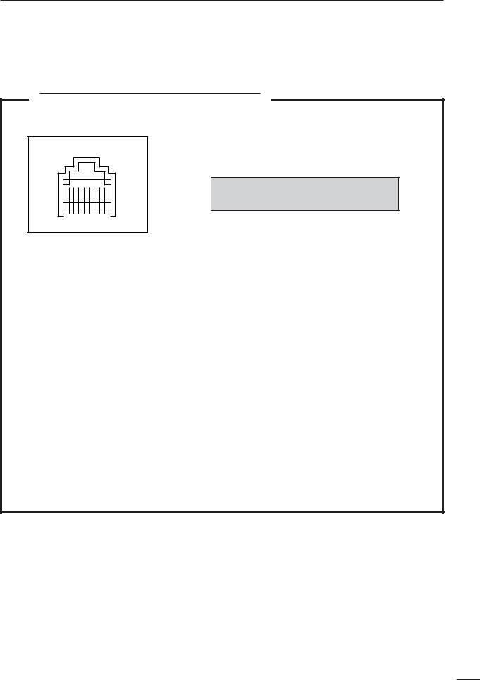
D Microphone connector |
1 |
MICROPHONE CONNECTOR INFORMATION
Rear panel view
87654321
HM-151
q +8 V DC output
w Frequency up/down e M8V SW
r PTT
t GND (Microphone ground) y Microphone input
u GND
i DATA IN
HM-103
q +8 V DC output
w Frequency up/down e M8V SW
r PTT
t GND (Microphone ground) y Microphone input
u GND
i Squelch switch
CAUTION:DO NOT short pin 1 to ground as this can damage the internal 8 V regulator.
• When HM-151 is connected
PIN NO. |
FUNCTION |
DESCRIPTION |
|
1 |
+8 V DC output |
Max. 10 mA |
|
|
|
|
|
2 |
Frequency up |
Ground |
|
|
|
||
Frequency down |
Ground through 470 |
||
|
|||
3 |
HM-151 connection |
Goes to ground to connect |
|
|
|
|
|
8 |
HM-151 data |
Control signal input |
|
|
|
|
|
|
|
|
|
• When HM-103 is connected |
|
||
|
|
|
|
PIN NO. |
FUNCTION |
DESCRIPTION |
|
1 |
+8 V DC output |
Max. 10 mA |
|
|
|
|
|
2 |
Frequency up |
Ground |
|
|
|
||
Frequency down |
Ground through 470 |
||
|
|||
3 |
HM-151 connection |
Open to pin 8 as SQL |
|
|
|
|
|
8 |
Squelch open |
“LOW” level |
|
|
|
||
Squelch closed |
“HIGH” level |
||
|
|||
|
|
|
|
|
|
|
|
10
1PANEL DESCRIPTION
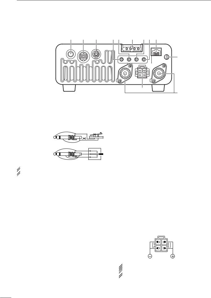
■Rear panel
q |
w |
e r t |
y u i o |
KEY |
ACC |
DATA |
MIC |
|
|||
|
|
|
GND |
|
|
|
!0 |
|
|
ANT2 |
ANT1 |
|
|
|
DC 13.8V |
!2
!1
qELECTRONIC KEYER JACK [KEY] (p. 22) Accepts a paddle to activate the internal electronic keyer.
•Selection between the internal electronic keyer and straight key operation can be made in the keyer set mode. (p. 50)
( )
When connecting a straight key
|
(dot) |
|
When connecting |
(com) |
|
(dash) |
||
a paddle |
||
|
 If you use an external electronic keyer, make sure
  the output voltage of the keyer is less than 0.4 V
  when keying the transmitter.
wACCESSORY SOCKET [ACC] (p. 12)
Enables connection to external equipment such as a TNC for data communications, a linear amplifier or an automatic antenna selector/tuner, etc.
•See page at right for socket wiring information.
eDATA SOCKET [DATA] (p. 12)
6-pin mini-DIN socket to connect a TNC (Terminal Node Controller), etc. for packet operation.
•See page at right for socket wiring information.
rVIDEO OUT JACK [VOUT] (p. 18) Outputs a video signal.
tCI-V REMOTE CONTROL JACK [REMOTE]
(p. 144)
Designed for use with a personal computer for remote control of the transceiver functions.
Used for transceiver operation with another Icom CI-V transceiver or receiver.
yTUNER CONTROL SOCKET [TUNER] (p. 20) Accepts the control cable from an optional AH-4
HF/50 MHz AUTOMATIC ANTENNA TUNER.
u RTTY JACK [RTTY] (p. 23)
Connects an external terminal unit for RTTY (FSK) operation.
•The keying polarity, mark/shift frequencies and etc. can be selected in quick set mode (p. 125).
iEXTERNAL SPEAKER JACK [EXT SP] (p. 18) Accepts a 4–8 speaker.
oMICROPHONE CONNECTOR [MIC] (p. 17) Accepts the supplied microphone (connected in parallel with the front panel’s [MIC] connector).
•See p. 2 for microphone notes.
•See p. 10 for microphone connector information.
!0GROUND TERMINAL [GND] (p. 15)
Connect this terminal to a station or vehicle ground to prevent electrical shocks, TVI, BCI and other problems.
!1ANTENNA CONNECTOR [ANT1], [ANT2] (p. 17) Accepts a 50 antenna with a PL-259 connector.
•[ANT1] is for connection to an HF/50 MHz antenna. •[ANT2] is for connection to an 144/430 MHz antenna. •ANT1 is used below and ANT2 above 60 MHz.
!2DC POWER SOCKET [DC13.8V] (p. 19)
Accepts 13.8 V DC through the supplied DC power cable.
Rear panel view
 NOTE: DO NOT use a cigarette lighter socket as a
power source when operating in a vehicle. The plug
 may cause voltage drops and ignition noise may be
  superimposed onto transmit or receive audio.
11
PANEL DESCRIPTION |
1 |
D DATA socket |
|
|
|
1 |
|||
DATA |
PIN No. |
NAME |
DESCRIPTION |
|
|
||
|
|
1 |
DATA IN |
Input terminal for data transmit. (1200 bps: AFSK/9600 bps: G3RUH, GMSK) |
|
||
|
|
|
|
|
|
||
|
|
2 |
GND |
Common ground for DATA IN, DATA OUT and AF OUT. |
|||
|
|
|
|
|
|
||
1 |
2 |
3 |
PTT P |
PTT terminal for packet operation. Connect to ground to activate the transmitter. |
|||
When grounded, microphone input (pin 6) of [MIC] connector will be disconnected. |
|||||||
3 |
4 |
|
|
||||
|
|
|
|
|
|||
5 |
6 |
4 |
DATA OUT |
Data out terminal for 9600 bps operation only. |
|||
|
|
|
|
|
|
||
Rear panel view |
5 |
AF OUT |
Data out terminal for 1200 bps operation only. |
||||
|
|
|
|
|
|||
|
|
Squelch out terminal. Becomes ground level when the transceiver receives a signal |
|||||
|
|
|
|
||||
|
|
|
|
which opens the squelch. |
|||
6SQL •To avoid interfering transmissions, connect squelch to the TNC to inhibit transmission
when squelch is open.
•Keep RF gain at a normal level, otherwise a “SQL”signal will not be output.
D ACC socket
|
ACC |
|
PIN No. |
NAME |
DESCRIPTION |
SPECIFICATIONS |
|||
|
|
|
|
|
|
|
|
|
|
|
|
|
|
1 |
8 V |
Regulated 8 V output. |
Output voltage |
: 8 V ±0.3 V |
|
|
|
|
|
Output current |
: Less than 10 mA |
||||
|
|
|
|
|
|
|
|||
|
|
|
|
|
|
|
|
|
|
|
|
|
|
2 |
GND |
Connects to ground. |
——— |
|
|
|
|
|
|
|
|
|
|
|
|
|
|
|
|
|
|
Input/output pin. (HF/50 MHz only) |
Ground level |
: –0.5 V to 0.8 V |
|
|
|
|
|
3 |
HSEND |
Goes to ground when transmitting. |
Output current |
: Less than 20 mA |
|
|
|
|
|
|
|
Grounded when transmits. |
Input current (Tx) |
: Less than 200 mA |
|
|
|
|
|
|
|
|
|
|
|
|
13 |
|
|
4 |
BDT |
Data line for the optional AT-180. |
——— |
|
|
|
|
|
|
|
|
|
|
||
9 |
10 |
11 |
12 |
5 |
BAND |
Band voltage output. |
Output voltage |
: 0 to 8.0 V |
|
5 |
6 |
7 |
8 |
||||||
1 |
2 |
3 |
4 |
|
|
(Varies with amateur band) |
|
|
|
|
|
|
|
6 |
ALC |
ALC voltage input. |
Control voltage |
: –4 V to 0 V |
|
Rear panel view |
Input impedance |
: More than 10 k |
|||||||
|
|
|
|||||||
q brown |
i gray |
|
|
Input/output pin. (144/430 MHz only) |
Ground level |
: –0.5 V to 0.8 V |
|||
7 |
VSEND |
Goes to ground when transmitting. |
Output current |
: Less than 20 mA |
|||||
w red |
|
o white |
|||||||
|
|
|
Grounded when transmits. |
Input current (Tx) |
: Less than 200 mA |
||||
e orange !0black |
|
|
|||||||
r yellow |
!1pink |
|
|
|
|
|
|||
8 |
13.8 V |
13.8 V output when power is ON. |
Output current |
: Max. 1 A |
|||||
t green |
!2light |
||||||||
|
|
|
|
|
|||||
y blue |
|
blue |
9 |
TKEY |
Key line for the optional AT-180. |
——— |
|
||
|
|
|
|||||||
u purple |
!3light |
|
|
|
|
|
|||
|
|
|
green |
|
|
|
“High” level |
: More than 2.4 V |
|
|
|
|
|
10 |
FSKK |
Controls RTTY keying |
“Low” level |
: Less than 0.6 V |
|
|
|
|
|
|
|
|
Output current |
: Less than 2 mA |
|
|
|
|
|
|
|
|
|
|
|
|
|
|
|
11 |
MOD |
Modulator input. |
Input impedance |
: 10 k |
|
|
|
|
|
Input level |
: Approx. 100 mV rms |
||||
|
|
|
|
|
|
|
|||
|
|
|
|
|
|
|
|
|
|
|
|
|
|
|
|
AF detector output. |
Output impedance |
: 4.7 k |
|
|
|
|
|
12 |
AF |
Fixed level, regardless of [AF] |
|||
|
|
|
|
Output level |
: 100–300 mV rms |
||||
|
|
|
|
|
|
position indefault settings. |
|||
|
|
|
|
|
|
|
|
||
|
|
|
|
|
|
|
|
|
|
|
|
|
|
13 |
SQLS |
Squelch output. |
SQL open |
: Less than 0.3 V/5 mA |
|
|
|
|
|
|
|
Grounded when squelch opens. |
SQL closed |
: More than 6.0 V/100 µA |
|
Color refers to the cable strands of the supplied cable.
12
1PANEL DESCRIPTION
• When connecting the ACC conversion cable (OPC-599)
|
13 |
|
Connect to ACC socket |
ACC 1 |
2 |
|
|
|
|
|
|
5 |
|||
9 |
10 |
11 |
12 |
4 |
|||
5 |
6 |
7 |
8 |
1 |
8 |
3 |
|
1 |
2 |
3 |
4 |
6 |
7 |
||
|
|||||||
|
|
|
|
q FSKK |
t AF |
||
|
|
|
|
w GND |
|
y SQLS |
|
|
|
|
|
e HSEND |
u 13.8 V |
||
|
|
|
|
r MOD |
|
i ALC |
|
ACC 2
2 |
5 |
4 |
|
1 |
3 |
6 |
7 |
q 8 V |
t ALC |
w GND |
y VSEND |
e HSEND |
u 13.8 V |
r BAND |
|
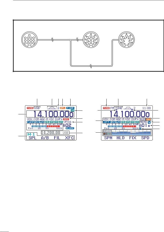
■Function display
!4 !3 !2!1 !0
o
q
i
u
w

 y
y  t
t
r
e
qFREQUENCY READOUT
Shows the operating frequency.
wMETER READOUTS
Shows received signal strength while receiving.
Shows either transmit power meter (Po), SWR, ALC or compression level meter (COM) while transmitting.
eMULTI-FUNCTION KEY GUIDE
Indicates the function of the multi-function keys. These alphanumeric readouts show a variety of in-
formation such as current functions of the “F” keys
[F-1] to [F-4].
rSPLIT FREQUENCY READOUT
Shows the transmit frequency during split operation.
tBLANK MEMORY INDICATOR
Appears when the displayed memory channel is not programmed (blank channel).
•This indicator appears both in VFO and memory modes.
@4 |
@3 |
@2 |
!5a |
|
!5b |
!6 |
@1 |
|
@0 |
||
|
||
|
!9 |
|
|
!8 |
|
!7 |
|
yMEMORY CHANNEL READOUT
Shows the selected memory channel or scan edge channel.
•Memory bank indicator (A to E) appears to the left of memory channel.
•This indicator appears both in VFO and memory modes.
uVFO/MEMORY INDICATORS
VFO A or B appears when VFO mode is selected; MEMO appears when memory mode is selected.
iVOICE RECODER INDICATORS
REC appears when the digital voice recoder function is activated.
oLOCK INDICATOR
Appears when the dial lock function is activated.
!0DIRECT FREQUENCY ENTRY INDICATOR (p. 29) Appears when the transceiver is ready for direct frequency entry.
•This indicator appears when [(F-INP)ENT] key on the HM-151 is pushed.
13

!1SPLIT INDICATOR
Appears during split opeation.
!2IF FILTER INDICATOR (p. 77) Shows the selected IF filter number.
!3PASSBAND WIDTH INDICATOR (p. 77, 79) Graphically displays the passband width for twin PBT operation and center frequency for IF shift operation.
!4MODE INDICATORS
Shows the selected operating mode.
• “-R” appears when CW reverse or RTTY reverse mode is selected.
!5PROGRAMMABLE/1 MHz TUNING STEP
INDICATORS
!5a appears when the 1 MHz quick tuning step is selected.
!5b appears when the programmable tuning step is selected.
!6FUNCTION INDICATORS
“ ” appears when the VOX function is activated.
“ ” appears when full break-in operation is selected and “
 ” appears when semi break-in operation is selected.
“ ” appears when the speech compressor is activated.
“ ,” “
,” “ ,” “
,” “ ” or “
  ” (OFF) appears when the fast time constant, middle time constant, slow time constant or AGC OFF is selected, respectively.
“ ” appears when the VSC (Voice Squelch Control) function is activated in phone (SSB, AM, FM, WFM) modes.
“ ” appears for negative offset and “
 ” appears for positive offset during duplex operation.
“ ” appears when the 9600 mode is activated for packet operation.
“ |
” appears when the preamp is ON, |
“ |
” appears when the 12 dB attenuator is |
|
ON. |
“ ” or “
 ” appears when the RIT or ∂TX function is activated.
“ ” appears when the noise blanker is activated.
“ ” appears when DSP noise reduction is activated.
“ ” appears when the manual notch function is activated.
“ ” appears when the automatic notch function is activated.
PANEL DESCRIPTION |
1 |
|
!7MULTI-FUNCTION SCREEN |
|
|
|
1 |
|
Shows the screens for the multi-function meter, sim- |
||
ple band scope, SWR meter, memory channel, voice recorder, memory keyer, DTMF memory encoder, RTTY decoder, IF filter selection or popup indication, etc.
!8PRIORITY WATCH INDICATOR
Appears while priority scan is activated.
!9SELECT MEMORY CHANNEL INDICATOR
Appears when select scan is enabled for the selected memory channel.
@01/4 FUNCTION INDICATOR
Appears when the 1⁄4-speed tuning function is activated in CW and RTTY modes.
@1EXTERNAL KEYPAD INDICATOR
Shows the memory keyer or voice memory channel number. This indication appears when “External Keypad (VOICE)” or “External Keypad (KEYER)” in the miscellaneous (others) set mode
(p. 137) is set to ON, and which one is activated.
<Example>
•“ ” appears when the memory keyer “M2” is transmitted.
•“ ” appears when the voice memory “T1” is transmitted.
@2CLOCK READOUT
Shows the current time.
•UTC time or local time can be selected.
@3TONE INDICATOR
Appears during FM tone operation.
•“ ,”“
,”“ ” or “
 ” appears when the repeater tone, tone squelch, DTCS squelch are activated, respectively.
@4TUNER INDICATOR
Appears when the optional automatic antenna tuner is activated.
•This indicator blinks while the tuner is tuning..
14
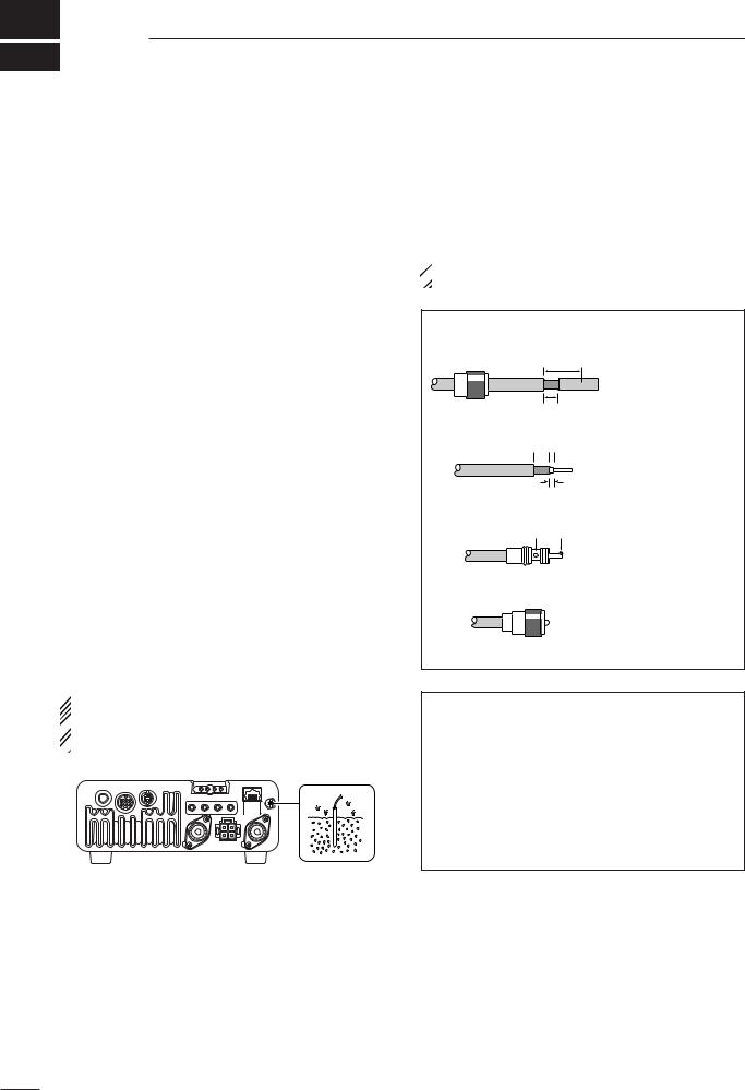
2INSTALLATION AND CONNECTIONS
■ Unpacking
After unpacking, immediately report any damage to the delivering carrier or dealer. Keep the shipping cartons.
For a description and a diagram of accessory equipment included with the IC-7000, see ‘Supplied accessories’ on p. i-1 of this manual.
■ Selecting a location
Select a location for the transceiver that allows adequate air circulation, free from extreme heat, cold, or vibrations, and away from TV sets, TV antenna elements, radios and other electromagnetic sources.
The base of the transceiver has an adjustable stand for desktop use. Set the stand to one of two angles depending on your operating conditions. (see description on right hand page)
■ Grounding
To prevent electrical shock, television interference (TVI), broadcast interference (BCI) and other problems, ground the transceiver through the GROUND terminal on the rear panel.
For best results, connect a heavy gauge wire or strap to a long, buried copper rod. Make the distance between the [GND] terminal and ground as short as possible.
 R WARNING: NEVER connect the [GND] ter-
minal to a gas pipe or electric conduit, since the
 connection could cause an explosion or electric
  shock.
■ Antenna connection
For radio communications the antenna is of critical importance for output power and sensitivity. Use wellmatched 50-ohm antennas and coaxial feedline. An SWR (standing wave radio) of 1.5:1 or lower is recommended when transmitting.
 CAUTION: Protect your transceiver from lightning
  by using a lightning arrestor.
PL-259 CONNECTOR INSTALLATION EXAMPLE
q
Coupling ring
w
e
r
30 mm
10 mm (soft solder)
10 mm Soft 

 solder
1–2 mm
solder solder
Slide the coupling ring down. Strip the cable jacket and soft solder.
Strip the cable as shown at left. Soft solder the center conductor.
Slide the connector body on and solder it.
Screw the coupling ring onto the connector body.
ANTENNA SWR
Each antenna is tuned for a specified frequency range and SWR increases outside that range. When the SWR is higher than approx. 2.0 : 1, the transceiver’s power drops to protect the final transistors. In this case, an antenna tuner is used to match the transceiver and antenna. Low SWR allows full power for transmitting even when using the antenna tuner. The IC-7000 has an SWR meter to monitor the antenna SWR continuously.
15
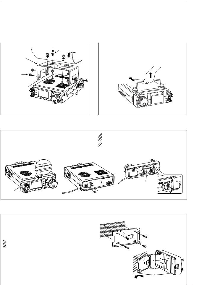
INSTALLATION AND CONNECTIONS |
2 |
■Installation
D Single body mounting
Spring washer
MB-62 |
Nut |
|
|
(optional) |
|
Supplied with |
|
the MB-62* |
|
Flat washer |
|
*CAUTION: Non-supplied screws (longer than 8 mm) may damage the internal units.
D Stand |
2 |
To raise the stand:
With the transceiver upside down, pull the stand towards the rear panel and then upwards, as illustrated below.
then up
Pull back
D Front panel separation
qWhile pulling the front panel latch towards you, slide the front panel to the left (fig. 1).
wAttach the optional OPC-1443 to the main body and tighten the supplied screw as in fig. 2.
eAttach the other end of the OPC-1443 to the detached front panel as in fig. 3.
 CAUTION: NEVER detach/attach the front panel
when connecting the DC power supply (or battery).
 Be sure to disconnect the DC power cable from the
  [13.8 V] socket on the transceiver rear panel.
fig. 1 |
fig. 2 |
fig. 3 |
|
|
To remove |
|
|
Separation cable |
|
|
(OPC-1443) |
Latch |
|
Separation cable |
|
|
(OPC-1443) |
D Front panel mounting
qAttach the MB-105 to a flat surface using the four |
fig. 1 |
|
supplied screws (fig. 1). |
||
|
||
wFix the detached front panel to the MB-105 as il- |
|
|
lustrated in fig. 2. |
|
|
BE CAREFUL to mount the MB-105 so that the |
|
|
front panel attaches with the correct side up. |
fig. 2 |
|
|
16
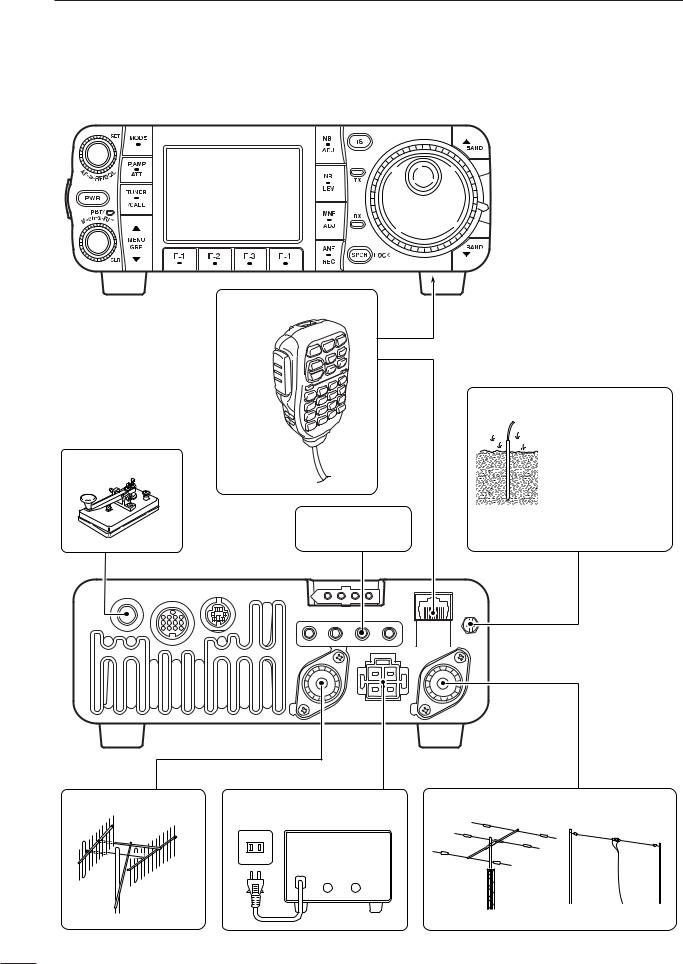
2INSTALLATION AND CONNECTIONS
■Required connections
MICROPHONE (p. 10)
STRAIGHT KEY
HM-151
RTTY TERMINAL
UNIT (p. 23)
GROUND (p. 15)
Use the heaviest gauge wire or strap available and make the connection as short as possible.
Grounding prevents electrical shocks, TVI and other problems.
KEY |
ACC |
DATA |
MIC |
|
GND
ANT2 |
ANT1 |
DC 13.8V
2 m/70 cm ANTENNA |
DC POWER SUPPLY (p.19) |
HF/50 MHz ANTENNA |
|
AC outlet A DC power supply |
|
13.8 V; at least 25 A
Red Black
+ _
17

INSTALLATION AND CONNECTIONS |
2 |
■Advanced connections
2
|
|
|
HEADPHONES |
|
OPC-589 (p. 152) |
|
|
DATA SOCKET (p. 12) |
|
|
|
6-pin mini DIN socket to |
|
|
|
connect to a TNC, etc. for |
|
|
|
packet operation. |
|
|
or |
|
|
|
SPEAKER |
VIDEO OUT |
|
|
|
to [VOUT] jack |
|
|
|
|
SM-20 |
|
|
Vout GND |
|
|
|
3.5(d) mm |
|
|
|
|
|
|
Selectable with the |
|
|
|
[PHONE/SPEAKER] |
|
DESKTOP (p. 151) |
|
switch on the back of |
ACC SOCKET (p. 12) |
MICROPHONE |
|
the front panel. |
KEY ACC |
DATA |
MIC |
EXTERNAL |
|
|||
|
|
GND |
SPEAKER (p. 151) |
|
ANT2 |
ANT1 |
|
|
DC 13.8V |
|
SP-7/SP-10 |
REMOTE (p. 144) |
AH-4 (p. 20) |
AH-2b |
Used for computer control and transceive |
|
|
operation. |
|
|
18
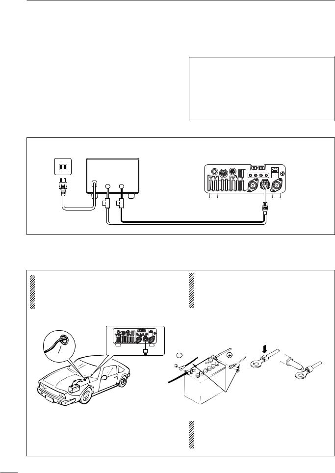
2INSTALLATION AND CONNECTIONS
■ Power supply connections
Use the DC power supply with a 25 A capacity when operating the transceiver with AC power. Refer to the diagrams below.
■Connecting a DC power supply
CAUTION: Before connecting the DC power cable, check the following important items. Make
sure:
•The [POWER] switch is OFF.
•Output voltage of the power source is 12–15 V. •DC power cable polarity is correct.
Red |
: positive + terminal |
Black |
: negative _ terminal |
AC outlet |
A DC power supply |
|
Transceiver |
|
|
|
|
|
|
|
13.8 V; at least 25 A |
|
|
|
|
Red |
Black |
|
|
|
+ |
_ |
|
|
|
|
|
|
DC power |
|
|
30 A fuses |
Supplied |
socket |
AC cable |
|
|
|
|
|
|
DC power cable |
|
|
■Battery connections
•RWARNING NEVER connect to a battery |
|
•DO NOT use the cigarette lighter socket for power |
||
without supplying a DC fuse, otherwise a fire |
|
connections. (See p. 11 for details) |
||
hazard occurs. |
|
•Attach a rubber grommet when passing the DC |
||
•NEVER connect the transceiver directly to a 24V |
|
power cable through a metal plate to prevent a |
||
battery. |
|
short circuit. |
|
|
CONNECTING A VEHICLE BATTERY |
|
|
|
Note: Use terminals for |
|
|
|
|
|
|
|
|
|
the cable connections. |
|
|
|
|
Crimp |
Grommet |
black |
|
red |
Solder |
|
|
|
|
|
|
|
12 V |
|
|
|
|
battery |
Supplied |
|
|
|
|
|
|
|
|
|
DC power cable |
|
|
|
IMPORTANT! |
|
|
|
|
Detailed installation notes for Icom mobile trans- |
||
|
|
ceivers to be fitted into vehicles are available. Con- |
||
|
|
tact your Icom dealer or distributor. |
||
19
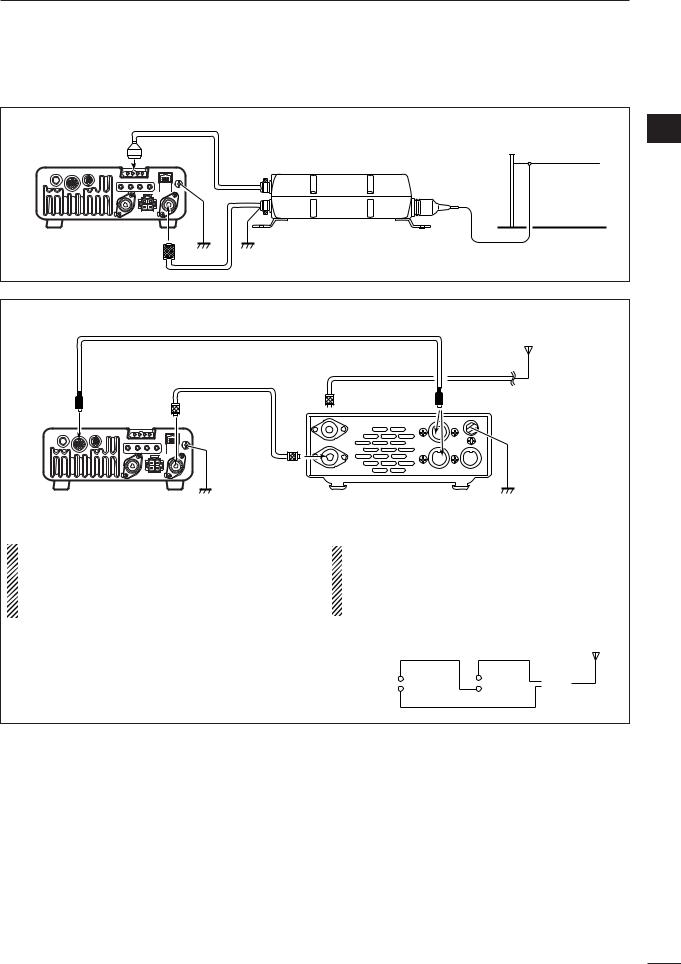
INSTALLATION AND CONNECTIONS |
2 |
■External antenna tuners
CONNECTING THE AH-4 |
|
2 |
|
|
|
||
IC-7000 |
|
Long wire or optional AH-2b |
|
|
AH-4 |
||
|
|
||
ANT1 |
|
|
|
Coaxial cable |
Ground |
Ground |
|
(from the AH-4) |
|||
|
|
CONNECTING THE AT-180
|
ACC cable supplied with the AT-180 |
|
|||
|
|
|
|
|
HF |
|
Coaxial cable supplied |
|
|
|
to 6 m |
|
with the AT-180 |
|
|
|
antenna |
[ACC] |
[ANT1] |
[ANT] |
|
AT-180 [ACC] |
Either of the two |
|
external connectors |
||||
IC-7000
Ground [TRANSCEIVER] Ground
•Turn the IC-7000’s power OFF when connecting |
•Do not connect [ANT2] to the AT-180. When using |
||||||
the AT-180, otherwise, the CPU may malfunction |
an HF to 2m/70cm dual or wide-band antenna, |
||||||
and the AT-180 may not function properly. |
use a duplexer between the AT-180 and antenna |
||||||
•The OPC-742 is required when using both the AT- |
since 2 m/70 cm signals do not pass through the |
||||||
180 and a 2m/70cm linear amplifier. |
AT-180. |
|
|
|
|
||
|
|
|
|
|
HF to 2 m/70 cm |
||
|
Transceiver |
AT-180 |
|
antenna |
|||
|
|
|
|
||||
|
[ANT 1] |
|
|
|
Duplexer |
||
|
|
|
|
|
|
|
|
|
[ANT 2] |
|
|
|
|
|
|
|
|
|
|
|
|
|
|
|
|
|
|
|
|
|
|
20
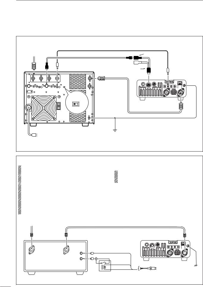
2INSTALLATION AND CONNECTIONS
■ Linear amplifier connections |
Use the [ANT1] connector when connecting an HF/50 |
|
MHz linear amplifier. |
CONNECTING THE IC-PW1/EURO |
|
|
|
|
|
|||
To an |
|
Remote control cable (supplied with the IC-PW1/EURO) |
|
|
||||
|
|
|
|
|
|
|
|
|
antenna |
ACC-1 |
ACC cable (supplied with the IC-PW1/EURO) |
7-pin side |
|
|
|||
ANT |
|
REMOTE |
OPC-599 conversion cable |
|
|
|||
|
|
|
|
|
|
ACC |
REMOTE |
|
|
|
|
|
INPUT1 |
|
|
GND |
|
|
|
EXCITER |
|
|
Transceiver |
ANT1 |
||
|
|
1 |
1&2 |
|
|
Coaxial cable |
|
|
|
|
|
|
|
|
|
|
|
|
|
|
|
|
|
(supplied with the IC-PW1/EURO) |
|
|
|
|
|
|
GND |
|
|
|
|
|
|
IC-PW1/EURO |
|
Ground |
|
|
|
|
AC outlet |
|
|
) |
|
|
|
||
|
Non-European versions: 100–120/220–240 V |
|
|
|
||||
(European version |
: 230 V |
|
|
|
|
|||
CONNECTING A NON-ICOM LINEAR AMPLIFIER |
|
|
|
|
R WARNING: |
|
|
|
|
•Set the transceiver output power and linear ampli- |
•The IC-7000 SEND relay is rated at 16 V and a |
|||
fier ALC output level referring to the linear ampli- |
0.5 A DC. If these levels are exceeded, a larger |
|||
fier instruction manual. Be sure the linear ampli- |
external relay must be used. |
|
||
fier keying circuit control voltage is compatible |
|
|
|
|
with the IC-7000, before connecting to HSEND |
|
|
|
|
line (ACC cable). |
|
|
|
|
•The ALC input level must be in the range 0 V to |
|
|
|
|
–4 V, and the transceiver does not accept positive |
|
|
|
|
voltage. Non-matched ALC and RF power settings |
|
|
|
|
could cause a fire or damage the linear amplifier. |
|
|
|
|
To an |
50 1 coaxial cable |
|
|
|
|
|
|
|
|
antenna |
|
|
|
|
|
|
|
Transceiver |
ANT1 |
|
|
|
|
|
|
|
|
|
GND |
RF OUT |
RF IN |
ALC (Blue) |
|
|
|
ALC |
|
|
|
|
|
|
|
|
|
KEY |
HSEND |
ACC |
|
|
Relay |
(Orange) |
Ground |
|
|
|
|
|
|
|
|
13.8V (Gray) |
ACC cable |
|
21
 Loading...