


INSTRUCTION MANUAL
HF/VHF/UHF ALL MODE TRANSCEIVER
i706MK™G
This device complies with Part 15 of the FCC rules. Operation is subject to the following two conditions: (1) This device may not cause harmful interference, and (2) this device must accept any interference received, including interference that may cause undesired operation.

IMPORTANT
Read this instruction manual carefully before attempting to operate the transceiver.
Save this instruction manual. This instruction manual contains important safety and operating instructions for the IC-706MKIIG.
PRECAUTIONS
RWARNING HIGH VOLTAGE! NEVER attach an antenna or internal antenna connector during transmission. This may result in an electrical shock or burn.
RNEVER apply AC to the [DC13.8V] socket on the transceiver rear panel. This could cause a fire or ruin the transceiver.
RNEVER apply more than 16 V DC, such as a 24 V battery, to the [DC13.8V] socket on the transceiver rear panel. This could cause a fire or ruin the transceiver.
RNEVER let metal, wire or other objects touch any internal part or connectors on the rear panel of the transceiver. This will cause electric shock.
RNEVER expose the transceiver to rain, snow or any liquids.
NEVER allow children to play with the transceiver.
AVOID using or placing the transceiver in areas with temperatures below –10°C (+14°F) or above +60°C (+140°F). Be aware that temperatures on a vehicle’s dashboard can exceed 80°C, resulting in permanent damage to the transceiver’s front panel if left there for extended periods.
AVOID placing the transceiver in excessively dusty environments or in direct sunlight.
AVOID placing the transceiver against walls or putting anything on top of the transceiver. This will obstruct heat dissipation.
During mobile operation, DO NOT operate the transceiver without running the vehicle’s engine. When transceiver power is ON and your vehicle’s engine is OFF, the vehicle’s battery will soon become exhausted.
Make sure the transceiver power is OFF before starting the vehicle. This will avoid possible damage to the transceiver by ignition voltage spikes.
During maritime mobile operation, keep the transceiver and microphone as far away as possible from the magnetic navigation compass to prevent erroneous indications.
BE CAREFUL! The heatsink will become hot when operating the transceiver continuously for long periods.
BE CAREFUL! If a linear amplifier is connected, set the transceiver’s RF output power to less than the linear amplifier’s maximum input level, otherwise, the linear amplifier will be damaged.
Use Icom microphones only (supplied or optional). Other manufacturer’s microphones have different pin assignments and connection to the IC-706MKIIG may damage the transceiver.
Beat signals may be heard on some frequencies. These will occur as a result of circuit construction.
For U.S.A. only
Caution: Changes or modifications to this transceiver, not expressly approved by Icom Inc., could void your authority to operate this transceiver under FCC regulations.
EXPLICIT DEFINITIONS
The explicit definitions described below apply to this instruction manual.
WORD |
DEFINITION |
|
RWARNING |
Personal injury, fire hazard or electric |
|
shock may occur. |
||
|
|
|
CAUTION |
Equipment damage may occur. |
|
NOTE |
If disregarded, inconvenience only. No risk |
|
of personal injury, fire or electric shock. |
||
|
||
|
|
i

TABLE OF CONTENTS
IMPORTANT ............................................................. |
i |
PRECAUTIONS ........................................................ |
i |
EXPLICIT DEFINITIONS .......................................... |
i |
TABLE OF CONTENTS ............................................ |
ii |
UNPACKING ............................................................. |
ii |
1 PANEL DESCRIPTION ..................................... |
1–8 |
■Front panel ............................................................... |
1 |
■Function switches ..................................................... |
3 |
■Rear and side panels ............................................... |
5 |
■Function display ....................................................... |
7 |
■Microphone (HM-103) ............................................... |
8 |
2 INSTALLATION AND CONNECTIONS .......... |
9–14 |
■Unpacking ................................................................. |
9 |
■Grounding ................................................................. |
9 |
■Antenna .................................................................... |
9 |
■Installation ................................................................ |
10 |
■Required connections ............................................... |
11 |
■Advanced connections ............................................. |
12 |
■Power supply connections ........................................ |
13 |
■External antenna tuners and linear amplifier ............ |
14 |
3 FREQUENCY SETTING ................................ |
15–19 |
■When first applying power (CPU resetting) .............. |
15 |
■Initial settings ............................................................ |
15 |
■VFO description ........................................................ |
16 |
■Frequency setting ..................................................... |
17 |
■Mode selection ......................................................... |
19 |
4 RECEIVE AND TRANSMIT .......................... |
20–38 |
■Functions for receive ................................................ |
20 |
■Functions for transmit ............................................... |
25 |
■Split frequency operation .......................................... |
29 |
■Tone squelch operation ............................................ |
31 |
■Tone scan operation ................................................. |
31 |
■One-touch repeater .................................................. |
32 |
■Auto repeater function .............................................. |
32 |
■Functions for CW ...................................................... |
33 |
■Functions for RTTY .................................................. |
35 |
■Packet operation ...................................................... |
37 |
■SWR ......................................................................... |
38 |
5 MEMORY AND SCAN OPERATION ............ |
39–44 |
■Memory channels ..................................................... |
39 |
■Memory channel selection ........................................ |
39 |
■Memory clearing ....................................................... |
39 |
■Memory/call programming ........................................ |
40 |
■Frequency transferring ............................................. |
41 |
■Memory names ......................................................... |
41 |
■Memo pads ............................................................... |
42 |
■Scan types ................................................................ |
43 |
■Preparation .............................................................. |
43 |
■Programmed scan operation .................................... |
44 |
■Memory scan operation ............................................ |
44 |
■Select memory scan operation ................................. |
44 |
■Priority watch ............................................................ |
44 |
6 REMOTE JACK (CI-V) INFORMATION ........ |
45–46 |
7 SET MODE .................................................... |
47–55 |
■General ..................................................................... |
47 |
■Quick set mode items ............................................... |
48 |
■Initial set mode items ............................................... |
50 |
8 MAINTENANCE ................................................... |
56 |
■Fuse replacement ..................................................... |
56 |
■Memory backup ........................................................ |
56 |
■Cleaning ................................................................... |
56 |
9 TROUBLESHOOTING .................................. |
57–58 |
10 OPTIONAL INSTALLATIONS/SETTINGS .. |
59–62 |
■Opening the transceiver case ................................... |
59 |
■UT-102 VOICE SYNTHESIZER UNIT ............................... |
59 |
■CR-282 HIGH-STABILITY CRYSTAL UNIT ........................ |
60 |
■IF filters ..................................................................... |
60 |
■UT-106 DSP RECEIVER UNIT ....................................... |
61 |
■MB-72 CARRYING HANDLE .......................................... |
61 |
■AT-180 internal switch description ............................ |
62 |
11 INTERNAL VIEWS ............................................. |
63 |
12 OPTIONS .................................................... |
64– 65 |
13 SPECIFICATIONS ............................................. |
66 |
14 MENU GUIDE .............................................. |
67–68 |
UNPACKING |
|
|
|
|
|
|
|
|
|
Accessories included with the IC-706MKIIG: |
|
|
|
|
|
|
Qty. |
|
|
|
|
qDC power cable* .................................................... |
1 |
|
|
|
|
wHand microphone (HM-103)................................... |
1 |
|
|
|
|
eSpare fuse (30 A) ................................................... |
2 |
q |
|
|
|
|
|
|
|
|
|
rSpare fuse (4 A) ..................................................... |
1 |
|
|
|
|
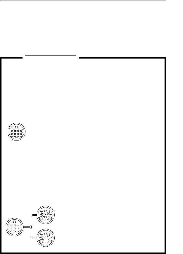
tRTTY key plug........................................................ |
1 |
w |
|
|
t y |
yElectronic keyer plug .............................................. |
1 |
|
|
|
|
uACC cable .............................................................. |
1 |
|
|
|
|
iFerrite bead** ......................................................... |
1 |
|
|
|
|
*OPC-639 for Europe versions (differs from the diagram at |
|
e |
r |
u |
i |
left), OPC-025D for other versions. |
|
|
|
|
|
**Not supplied with some versions. |
|
ii
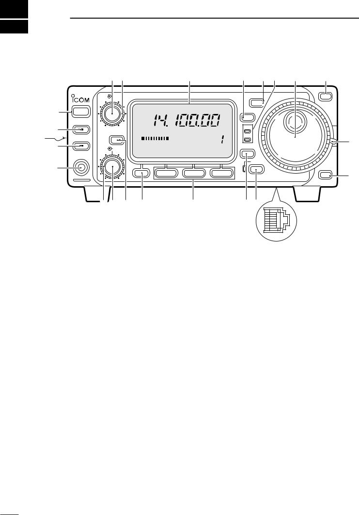
1 PANEL DESCRIPTION
■Front panel
|
w e |
|
r |
t |
y u |
i |
o |
AF |
RF/SQL |
HF/VHF/UHF TRANSCEIVER |
i706MK™G |
|
MODE |
|
Y |
BAND
q |
POWER |
USB |
TS |
|
|||
|
|
||
|
P.AMP/ATT |
|
|
@2 |
|
|
|
|
|
RX |
|
|
S1 3 5 7 |
9 20 40 |
60dB |
VFO A |
|
|
|
@1 |
TUNER/CALL RIT/ |
TX |
|
||||
|
|
|
|
|
|||
|
|
|
CH |
|
!0 |
||
@0 |
SUB |
PO |
5 |
10 |
DISPLAY |
||
M-CH SHIFT |
M1 SPL A/B A=B |
|
|||||
|
PHONES |
|
|
|
|
|
|
|
|
|
|
|
|
LOCK |
|
!9 |
|
|
|
|
|
BAND |
|
|
|
|
F-1 |
F-2 |
F-3 |
Z |
o |
|
|
|
|
|
|
||
|
!8!7 !6 |
!5 |
|
!4 |
!3!2 |
|
|
!1
q POWER SWITCH [POWER] (p. 15)
Turns power ON and OFF.
•Push momentarily to turn power ON.
•Push for 2 sec. to turn power OFF.
w AF GAIN CONTROL [AF] (inner control; p. 15) Rotate clockwise to increase the audio output from the speaker; rotate counterclockwise to decrease the audio output from the speaker.
eRF GAIN CONTROL/SQUELCH CONTROL [RF/SQL] (outer control; p. 22)
Adjusts the squelch threshold level (to mute noise when receiving no signal) in all modes.
This control can be used for RF gain control to adjust receiver gain manually.
•RF gain selection can be set in initial set mode (p. 50).
•RF gain is usable in SSB/CW/RTTY modes only.
r FUNCTION DISPLAY
Shows the operating frequency, dot matrix indications, selected memory channel, etc. See p. 7 for details.
t TUNING STEP SWITCH [TS] (pgs. 17, 18)
Push momentarily to cycle between 1 Hz/10 Hz, programmable and 1 MHz tuning steps.
•1 and 10 Hz steps are only available in SSB, CW and RTTY modes; 1 MHz steps are only available in FM, WFM and AM modes.
Push for 2 sec. to toggle between 1 and 10 Hz steps, or; when the programmable tuning steps is indicated, push for 2 sec. to enter programmable tuning step mode.
y MODE SWITCH [MODE] (p. 19)
Push momentarily to cycle through the operating modes:
USB/LSB CW/CWå RTTY/åRTTY
FM/WFM/AM
Push and hold for 2 sec. to toggle between the following operating modes:
USB LSB CW CWå RTTY åRTTY
FM WFM AM FM, etc.
u RECEIVE/TRANSMIT INDICATORS [RX]/[TX]
[RX] lights green while receiving (and squelch opens); [TX] lights red while transmitting.
i MAIN DIAL
Changes the displayed frequency, selects initial set mode items, etc.
o UP/DOWN (BAND) SWITCHES [Y/Z(BAND)]
Push to select a band.
•Can also be used to advance quick set mode items, initial set mode items, etc.
Push and hold to scroll through the bands continuously.
!0MAIN DIAL TENSION LATCH
Selects the main dial tension.
• 2 positions are available.
!1MICROPHONE CONNECTOR (p. 8)
Modular-type microphone connector—connects the supplied microphone (HM-103).
•The optional OPC-589 can be used to connect an 8-pin microphone such as the SM-8 or SM-20, if desired.
•A microphone connector is also available on the rear
1

panel. DO NOT connect 2 microphones simultaneously.
!2LOCK SWITCH [LOCK]
Push momentarily to turn the dial lock function ON and OFF.
•The dial lock function electronically locks the main dial.
When the optional UT-102 VOICE SYNTHESIZER UNIT is installed (p. 52), push for 2 sec. to have the frequency, etc. announced.
•UT-102 operation can be adjusted in initial set mode (pgs. 53, 54).
LOCK
Lights while the lock function is activated.
!3DISPLAY SWITCH [DISP] (p. 68)
Push momentarily to select one of the three menu sets: M1 to M4, S1 to S4 and G1 to G4.
Push for 2 sec. to select quick set mode.
!4FUNCTION SWITCHES [F1]/[F2]/[F3] (pgs. 3, 4, 68) Push to select the function indicated in the dot matrix display above these switches.
• Functions vary depending on the menu set selected.
!5MENU SWITCH [MENU] (p. 68)
Push this switch one or more times to select menus within a menu set (M, S or G), or push to advance through the quick set mode and initial set mode displays.
Push and hold to jump between two different function menu sets.
!6RIT/SUB DIAL SWITCH [RIT/SUB] (p. 20)
Push to toggle the RIT or SUB DIAL function ON and OFF—initial set mode is used to select the desired action*.
•Lights green when the SUB DIAL function is ON; lights red when the RIT function is ON.
•Use the [M-CH] control to vary the RIT frequency or SUB DIAL frequency (see above).
When the RIT function is ON, push for 2 sec. to add or subtract the shifted frequency to the oper-
ating frequency.
RIT
SUB
Lights red while the RIT function is activated; green while the SUB DIAL function is activated.
*Even if RIT is selected in initial set mode, RIT cannot be selected when operating AM, FM or WFM modes.
!7SHIFT CONTROL [SHIFT] (outer control; p. 20) Shifts the center frequency of the receiver’s IF passband.
•Rotate the control clockwise to shift the center frequency higher, or rotate the control counterclockwise to shift the center frequency lower.
•When the graphic menu display (G2) is selected, the IF passband is graphically displayed and changes in accordance with the [SHIFT] control (see p. 20).
PANEL DESCRIPTION 1
!8M-CH CONTROL [M-CH] (inner control)
When the RIT or SUBDIAL functions are OFF, rotate to select a memory channel number (p. 35).
Shifts the receive frequency while the RIT function is ON in SSB, CW and RTTY modes (see below and p. 20).
•RIT variable range is ± 9.99 kHz
Changes the operating frequency in the selected tuning steps while the SUB DIAL function is ON (p. 18).
!9HEADPHONE JACK [PHONES] (p. 12) Accepts headphones with 4–16 Ω impedance.
•When headphones are connected, no receive audio comes from the speaker.
•When the PHONES/SPEAKER switch on the back of the front panel is set to the [SPEAKER] position, an external speaker can be connected. This is convenient for mobile or outdoor operation.
@0TUNER/CALL SWITCH [TUNER/CALL]
(pgs. 26, 27)
During HF/50 MHz operation, push this switch momentarily to toggle the automatic antenna tuner function ON/OFF.
•An optional antenna tuner must be connected.
During HF/50 MHz operation, push this switch for 2 sec. to manually tune the antenna.
•An optional antenna tuner must be connected.
During 144/430 MHz operation, push this switch momentarily to select the call channel (or the previous channel/frequency when the call channel is already selected). (p. 39)
•“C1” is the 144 MHz call channel and “C2” is the 430 MHz call channel.
TUNER/CALL
Lights while the automatic tuning function is activated.
@1FRONT PANEL LATCH (p. 10)
Pull away from the transceiver (towards yourself when looking at the front of the transceiver) to detach the front panel from the main body of the transceiver.
@2PREAMP/ATTENUATOR SWITCH [P.AMP/ATT]
(p. 21)
Push momentarily to turn the preamp ON or OFF.
Push and hold to turn the 20 dB attenuator ON; push momentarily to turn the attenuator OFF.
•Lights green when the preamp is ON; lights red when the 20 dB attenuator is ON.
P.AMP/ATT
Lights green while the preamp is activated; lights red while the attenuator is activated.
2
1 PANEL DESCRIPTION
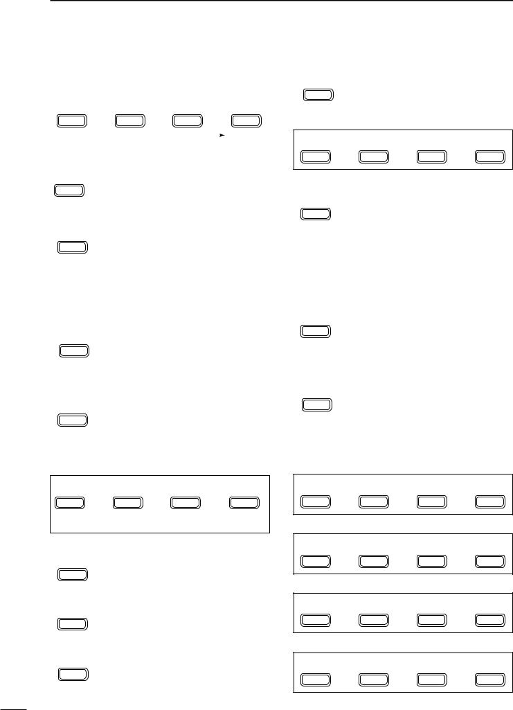
■Function switches
DM1 FUNCTIONS
M1 |
SPL |
A/B |
A=B |
|
MENU |
F-1 |
F-2 |
F-3 |
|
|
|
|
|
XFC |
|
|
|
|
|
|
|
|
|
|
|
|
|
||
SPLIT OPERATION (p. 29) |
|
|
||
SPL |
Toggles the split function ON and OFF. |
|||
• “ä”appears when the split function is ON. |
||||
F-1 |
• The function of [F-3] changes to XFC when the |
|||
|
split function is ON. |
|
|
|
VFO A/B SELECTION (p. 16) |
|
|||
A/B |
Toggles between VFO A and VFO B in |
|||
VFO mode. |
|
|
||
F-2 |
Toggles between transmission VFO and |
|||
|
reception VFO during split operation. |
|||
Toggles between the transmit and receive frequencies (and modes) of memory channels when the split function is turned ON.
VFO EQUALIZATION (p. 16)
Equalizes the frequency and operating A=B mode of the two VFO’s.
F-3 • The rear (undisplayed) frequency and operating mode are equalized to the front (displayed) VFO frequency and operating mode.
TRANSMIT FREQUENCY CHECK (p. 29)
Appears when the split function is turned XFC ON—monitors the transmit frequency
F-3 when pushed and held.
•While pushed, the transmit frequency can be changed with the main dial.
DM2 FUNCTIONS
M2 MW MÜV V/M
MENU |
F-1 |
F-2 |
F-3 |
MCL(in memory mode)
MEMORY WRITE (p. 40)
Stores the displayed frequency and oper- MW ating mode into the displayed memory F-1 channel.
MEMORY TRANSFER (p. 41)
Transfers the frequency and operating MÜV mode in the selected memory channel to a
F-2 VFO.
VFO/MEMORY (p. 39)
V/M modes.Toggles between VFO and memory
F-3
MEMORY CLEAR (p. 39)
Clears the selected memory channel’s MCL contents.
F-2 • “}” appears.
DM3 FUNCTIONS
M3 FIL NB MET
MENU |
F-1 |
F-2 |
F-3 |
NARROW FILTER (p. 23)
Toggles the narrow filter (or wide filter— FIL push for 2 sec.) ON and OFF.
F-1 • “ã”appears when the narrow filter is ON; “ç” appears when the wide filter is ON.
•An optional narrow filter and presetting in initial set mode (p. 51) is necessary to use the following:
CW/RTTY narrow: FL-100, FL-101 or FL-232 SSB narrow: FL-223
SSB wide: FL-103
NOISE BLANKER (p. 21)
NB |
Turns the noise blanker ON and OFF. |
• The noise blanker does not function in FM and |
|
F-2 |
WFM modes; the “AM Noise blanker” item in |
|
initial set mode must be set to ON for the noise |
|
blanker to work in AM mode (p. 53). |
METER SELECTION (p. 25)
Selects the type of meter displayed (during MET transmit) in the function display.
F-3 • Power, ALC or SWR metering can be selected.
• Only an S-meter is available for receive.
DM4 FUNCTIONS
DURING SSB/AM OPERATION:
M4 VOX COM AGC
MENU |
F-1 |
F-2 |
F-3 |
DURING CW OPERATION:
M4 |
i/4 |
BRK |
AGC |
MENU |
F-1 |
F-2 |
F-3 |
DURING RTTY OPERATION: |
|
||
M4 |
1/4 |
|
AGC |
MENU |
F-1 |
F-2 |
F-3 |
DURING FM OPERATION: |
|
|
|
M4 |
VOX |
TSQ |
TON |
MENU |
F-1 |
F-2 |
F-3 |
3
VOX FUNCTION (p. 26)
VOX Toggles the VOX function ON and OFF.
• The [VOX GAIN] and [ANTI VOX] are avail- F-1 able on the side panel.
• VOX delay can be set in quick set mode (p. 48).
SPEECH COMPRESSOR (p. 26)
COM OFF.Toggles the speech compressor ON and
F-2 |
• The [COMP GAIN] control is available on the |
|
side panel. |
AGC (p. 21)
AGC cuit.Changes the time constant of the AGC cir-
F-3
BREAK-IN (p. 33)
BRK Selects semi break-in, full break-in (QSK) and break-in OFF
F-2 • “BK” or “F-BK” appears when selecting semi break-in or full break-in, respectively.
•An external switch, such as a foot switch, is necessary to connect to the ACC socket (pin 3, pin 7 or RTTY SEND—see p. 35) to use no break-in operation.
1/4 FUNCTION (p. 36)
1/4 |
Toggles the 1/4 function ON and OFF. |
• When the 1⁄4 function is ON, a bar appears |
|
F-1 |
under the 1⁄4 indication and fine tuning can be |
|
used. |
TONE SQUELCH (p. 31) |
|
TSQ |
Toggles the tone squelch function ON and |
F-2 |
OFF (a tone squelch frequency must be |
selected in Quick Set mode). |
|
• “FM-TSQL” appears when the function is ON.
REPEATER TONE OPERATION (p. 30)
TON |
Toggles the subaudible tone encoder for |
repeater use ON and OFF. |
|
F-3 |
• “FM-T” appears when the function is ON. |
|
Transmits a 1750 Hz tone burst when |
|
pushed and held during transmission. |
|
• Tone frequencies or tone burst can be set in |
|
initial set mode (p. 49). |
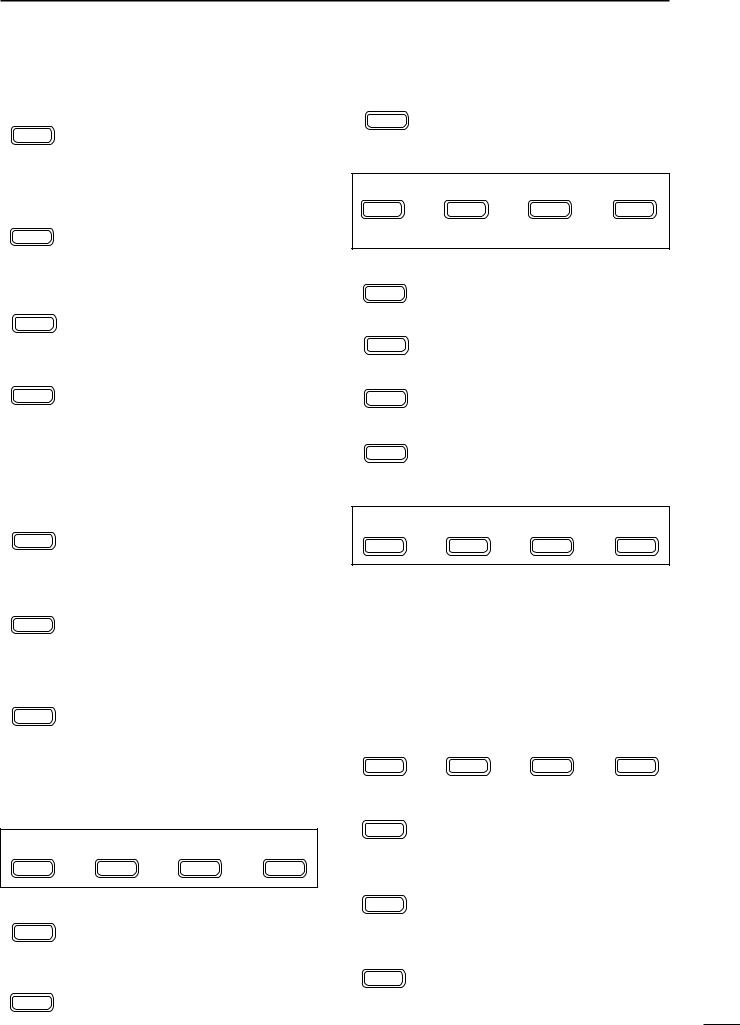
DS1 FUNCTIONS
S1 |
MW |
MPW |
MPR |
MENU |
F-1 |
F-2 |
F-3 |
MW |
MEMORY WRITE (p. 40) |
|
|
Stores the displayed frequency and oper- |
|||
F-1 |
ating mode into the displayed memory |
||
|
channel. |
|
|
MEMO PAD WRITE (p. 42)
MPW Stores the displayed frequency and oper- F-2 ating mode into a memo pad.
PANEL DESCRIPTION 1
MPR MEMO PAD READ (p. 42)
Calls up a memo pad.
F-3
DS2 FUNCTIONS
S2 SCN PRI V/M
MENU |
F-1 |
F-2 |
F-3 |
SEL(in memory mode)
SCN SCAN (p. 44)
Starts and stops the scan function.
F-1
PRI PRIORITY WATCH (p. 44)
Starts and stops priority watch.
F-2
|
SELECT SCAN (p. 44) |
SEL Toggles the select setting ON and OFF for |
|
F-2 |
the selected memory channel. |
V/M |
VFO/MEMORY (p. 44) |
Toggles between VFO and memory |
|
F-3 |
modes. |
DS3 FUNCTIONS
S3 7 50 144
MENU |
F-1 |
F-2 |
F-3 |
QUICK BAND CHANGE FUNCTION (p. 19)
This item provides access to the band stacking register. By default the 7, 50 and 144 MHz bands are displayed. Push [F-1] to [F-3] for 2 sec. to select a new band if desired.
•A mode is memorized along with the frequency for each band.
DS4 FUNCTIONS (may be optional for some ver.)
S4 |
ANF |
NR |
NRL |
MENU |
F-1 |
F-2 |
F-3 |
|
|
||
ANF |
AUTOMATIC NOTCH FILTER (p. 24) |
||
F-1 |
This function automatically attenuates beat |
||
tones, tuning signals, etc., even if they are |
|||
|
moving. |
|
|
NR |
NOISE REDUCTION (p. 24) |
|
|
This function reduces noise components |
|||
F-2 |
and picks out desired signals which are |
||
|
buried in the noise. |
|
|
NRL |
NOISE REDUCTION DISPLAY (p. 24) |
||
This displays the noise reduction level |
|||
F-3 |
when using the noise reduction function. |
||
4
1 PANEL DESCRIPTION
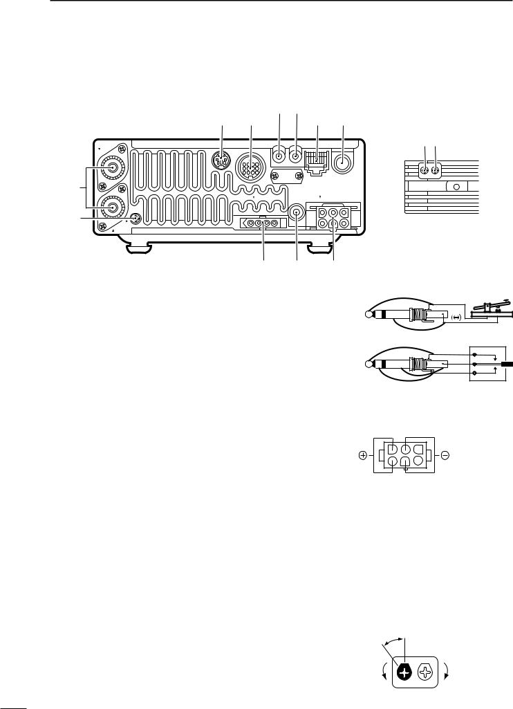
■Rear and side panels
t y
e r |
u i |
ANT 1
KEY
MIC
w
TUNER |
EXT SP |
DC 13.8V |
|
|
q
GND |
ANT 2 |
!1 !0 o
!2!3
COMP BEEP GAIN /SIDE T
q GROUND TERMINAL [GND] (p. 9)
Connect this terminal to a ground to prevent electrical shocks, TVI, BCI and other problems.
wANTENNA CONNECTORS [ANT 1], [ANT 2] (p. 11) Accept a 50 Ω antenna with an PL-259 type plug.
•[ANT 1] is for connection to an HF/50 MHz antenna.
•[ANT 2] is for connection to 144 MHz antenna.
•These connectors are switched above or below 60 MHz.
eDATA JACK [DATA] (p. 12)
6-pin min DIN jack to connect a TNC, etc. for packet operation.
rACCESSORY SOCKET [ACC] (p. 6)
Enables connection to external equipment such as a TNC for data communications, a linear amplifier or an automatic antenna selector/tuner, etc.
• See page at right for socket information.
tRTTY JACK [RTTY] (p. 35)
Connects an external terminal unit for RTTY (FSK) operation.
•The keying polarity and mark/shift frequencies can be selected in quick set mode (p. 48).
yCI-V REMOTE CONTROL JACK [REMOTE]
(p. 45)
Designed for use with a personal computer for remote operation of transceiver functions.
u MICROPHONE CONNECTOR [MIC] (p. 11) Accepts the supplied microphone (connected in parallel with the front panel’s [MIC] connector).
•See pgs. 1 and 2 for microphone notes.
•See p. 8 for microphone connector information.
iELECTRONIC KEYER JACK [KEY] (p. 33) Accepts a paddle to activate the internal electronic keyer.
• Selection between the internal electronic keyer and
5straight key operation can be made in quick set mode. (p. 49)
When connecting |
( ) |
|
|
||
a straight key |
|
|
When connecting |
(dot) |
|
(com) |
||
a paddle |
||
(dash) |
||
|
o DC POWER SOCKET [DC13.8V] (p. 13)
Accepts 13.8 V DC through the supplied DC power cable.
Rear panel view
!0EXTERNAL SPEAKER JACK [EXT SP] (p. 12) Accepts a 4–16 Ω speaker.
!1TUNER CONTROL SOCKET [TUNER] (p. 12) Accepts the control cable from an optional AH-3 HF
AUTOMATIC ANTENNA TUNER.
!2SPEECH COMPRESSION LEVEL CONTROL [COMP GAIN] (p. 26)
Adjusts the compression level.
•This control is available only when the speech compressor is ON.
Recommended level
Counterclockwise |
Clockwise |
decreases |
increases |
COMP |
BEEP |
GAIN |
/SIDE T |
PANEL DESCRIPTION 1
!3BEEP/SIDETONE CONTROL [BEEP/SIDETONE]
Adjusts the beep tone and CW side tone audio levels.
TECHNICAL INFORMATION
• ACC SOCKET
|
ACC |
|
PIN # |
NAME |
DESCRIPTION |
SPECIFICATIONS |
COLOR |
|||||
|
|
|
|
|
|
|
|
|
|
|
||
|
|
|
|
1 |
8 V |
Regulated 8 V output. |
Output voltage |
: 8 V ±0.3 V |
brown |
|||
|
|
|
|
Output current |
: Less than 10 mA |
|||||||
|
|
|
|
|
|
|
|
|||||
|
|
|
|
|
|
|
|
|
|
|
|
|
|
|
|
|
2 |
GND |
Connects to ground. |
|
|
|
|
red |
|
|
|
|
|
|
|
|
|
|||||
|
|
|
|
|
|
|
|
|
|
|
|
|
|
|
|
|
|
|
Input/output pin (HF/50 MHz). |
Ground level |
|
: –0.5 V to 0.8 V |
|
||
|
|
|
|
|
|
Goes to ground when transmitting. |
|
|
||||
|
|
|
|
3 |
HSEND |
Input current |
|
: Less than 20 mA |
orange |
|||
|
|
|
|
When grounded, transmits (connected to 8V |
|
|||||||
|
|
|
|
|
|
line thru 2.2 kΩ resistance/144 MHz operation). |
(HF/50 MHz bands) |
|
||||
|
|
|
|
|
|
|
|
|
|
|
||
|
|
|
|
|
|
|
|
|
|
|
|
|
|
|
|
|
4 |
BDT |
Data line for the optional AT-180. |
|
|
|
|
yellow |
|
|
|
|
|
|
|
|
|
|||||
|
|
|
|
|
|
|
|
|
|
|
|
|
|
|
|
|
5 |
BAND |
Band voltage output. |
Output voltage |
: 0 to 8.0 V |
green |
|||
|
|
|
|
(Varies with amateur band) |
||||||||
|
|
|
|
|
|
|
|
|
|
|
||
|
|
|
|
|
|
|
|
|
|
|
||
|
|
|
|
6 |
ALC |
ALC voltage input. |
Control voltage |
: –4 to 0 V |
blue |
|||
|
|
|
|
Input impedance |
: More than 10 kΩ |
|||||||
|
|
|
|
|
|
|
|
|||||
|
13 |
|
|
|
|
|
|
|
|
|
|
|
|
|
|
|
|
Input/output pin (144 MHz). |
|
|
|
|
|
||
9 |
10 |
11 |
12 |
|
|
Ground level |
|
: –0.5 V to 0.8 V |
|
|||
5 |
6 |
7 |
8 |
|
|
Goes to ground when transmitting. |
|
|
||||
7 |
VSEND |
Input current |
|
: Less than 20 mA |
purple |
|||||||
1 |
2 |
3 |
4 |
When grounded, transmits (connected to 8V |
|
|||||||
|
|
|
|
|
|
line thru 2.2 kΩ resistance/HF•50 MHz operation). |
(144 MHz band) |
|
||||
|
|
|
|
|
|
|
|
|
|
|
||
Rear panel |
|
|
|
|
|
|
|
|
||||
8 |
13.8 V |
13.8 V output when power is ON. |
Output current |
: Max. 1 A |
gray |
|||||||
|
view |
|
||||||||||
|
|
|
|
|
|
|
|
|
|
|||
|
|
|
|
|
|
|
|
|
|
|
|
|
|
|
|
|
9 |
TKEY |
Key line for the AT-180. |
|
|
|
|
white |
|
|
|
|
|
|
|
|
|
|||||
|
|
|
|
|
|
|
|
|
|
|
|
|
|
|
|
|
10 |
FSKK |
RTTY keying input. |
Ground level |
|
: –0.5 to 0.8 V |
black |
||
|
|
|
|
Connected in parallel to the [RTTY] jack. |
Input current |
|
: Less than 10 mA |
|||||
|
|
|
|
|
|
|
|
|||||
|
|
|
|
|
|
|
|
|
|
|
||
|
|
|
|
11 |
MOD |
Modulator input. |
Input impedance |
: 10 kΩ |
pink |
|||
|
|
|
|
Input level |
|
: Approx. 100 mV |
||||||
|
|
|
|
|
|
|
rms |
|
|
|
|
|
|
|
|
|
12 |
AF |
AF detector output. |
Output impedance |
: 4.7 kΩ |
light |
|||
|
|
|
|
Fixed, regardless of [AF] position. |
Output level |
|
: 100 to 350 mV rms |
blue |
||||
|
|
|
|
|
|
|
||||||
|
|
|
|
|
|
|
|
|
|
|
||
|
|
|
|
13 |
SQLS |
Squelch output. |
SQL open |
: Less than 0.3 V/5 mA |
light |
|||
|
|
|
|
Goes to ground when squelch opens. |
SQL closed |
: More than 6.0 V/100 µA |
green |
|||||
|
|
|
|
|
|
|||||||
|
|
|
|
|
|
|
|
|
|
|
|
|
• When connecting the ACC conversion cable (OPC-599)
2 |
5 |
FSKK |
AF |
|
4 |
GND |
SQLS |
||
1 |
3 |
|||
HSEND |
13.8 V |
|||
8 |
7 |
|||
6 |
MOD |
ALC |
||
13 |
|
|||
|
|
|
Color refers to the cable strands of the supplied cable.
9 |
10 |
11 |
12 |
ACC 1 |
|
|
|
5 |
6 |
7 |
8 |
|
|
||
|
|
|
|
||||
1 |
2 |
3 |
4 |
|
|
8 V |
ALC |
|
|
|
|
2 |
5 |
||
|
|
|
|
4 |
GND |
VSEND |
|
|
|
|
|
1 |
3 |
||
|
|
|
|
HSEND |
13.8 V |
||
|
|
|
|
6 |
7 |
||
|
|
|
|
BAND |
|
||
|
|
|
|
|
|
|
|
ACC 2
6
1 PANEL DESCRIPTION
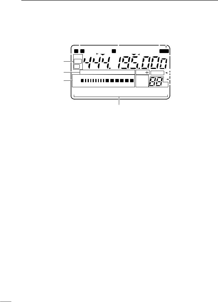
■Function display
q w ea r
|
|
|
|
|
|
|
|
|
|
|
|
|
|
|
|
|
|
|
|
|
|
|
|
|
|
|
|
|
|
|
|
|
|
|
|
|
|
|
|
|
|
|
|
|
|
|
|
|
|
|
|
|
|
|
|
|
|
|
|
eb |
|
|
N W LSB USB CW R RTTY AM WFM |
|
TSQL |
SPL |
|
|
|
|
|
|
|
||||||||||||||||
|
|
|
|
|
|
|
|
||||||||||||||||||||||
|
DSP |
|
|
|
|
|
|
|
|
|
|
|
|
|
|
|
|
|
|
|
|
|
|
|
|||||
|
|
|
|
|
|
|
|
|
|
|
|
|
|
|
|
|
|
|
|
|
|
|
|
||||||
|
|
|
|
|
|
|
|
|
|
|
|
|
|
|
|
|
|
|
|
|
|
|
|
|
|||||
!4 |
|
|
ANF |
|
|
|
|
|
|
|
|
|
|
|
|
|
|
|
|
|
|
|
t |
||||||
|
|
|
|
|
|
|
|
|
|
|
|
|
|
|
|
|
|
|
|
||||||||||
|
|
|
NR |
|
|
|
|
|
|
|
|
|
|
|
|
|
|
|
|
|
|
|
|
y |
|||||
!3 |
|
|
|
NB VOX F-BK COM FAGC DUP |
|
|
|
|
|
|
|
|
|
|
|||||||||||||||
|
|
|
|
|
|
|
|
|
|
|
|
|
|||||||||||||||||
|
|
|
|
|
|
|
|
|
|
|
|
|
|||||||||||||||||
|
|
|
|
|
|
|
|
|
|
|
|
|
|
|
|
||||||||||||||
|
|
|
|
BLANK |
|
|
i u |
||||||||||||||||||||||
|
|
|
|
|
|
|
|||||||||||||||||||||||
|
|
|
|
S1 |
3 5 |
7 |
9 20 |
40 |
60dB |
VFO A |
|
|
|
|
|
|
|
|
|
|
|
|
|
||||||
|
|
|
|
|
S |
|
|
|
|
|
|
o |
|||||||||||||||||
!2 |
|
ALC |
|
|
|
|
|
∞ |
|
VFO B |
|
|
|
|
|
|
|
|
|
||||||||||
|
|
|
|
|
|
|
|
|
|
|
|
|
|
|
|
||||||||||||||
|
|
|
|
|
|
|
|
|
|
|
|
|
|
|
|
|
|||||||||||||
|
SWR PO 1 |
1.5 |
2 |
|
3 5 |
|
10 |
MEMO |
|
|
|
CH |
|
|
|
|
|
!0 |
|
||||||||||
|
|
|
|
|
|
|
|
||||||||||||||||||||||
M1 SPL A/B A=B
q NARROW/WIDE FILTER INDICATORS
“ã” appears when selecting AM narrow or FM narrow modes.
When installing an optional narrow filter, narrow mode can be selected in CW, RTTY and SSB modes.
•When the SSB wide filter is installed, “ç” appears during wide mode selection.
w MODE INDICATORS
Show the operating mode.
ePROGRAMMABLE/1 MHz TUNING STEP
INDICATORS
a appears when the programmable tuning step is selected.
b appears when the 1 MHz tuning step is selected.
r SPLIT INDICATOR
Shows that the split frequency function is activated.
t FREQUENCY READOUT
Shows the operating frequency.
•“C” appears in place of the 1 Hz digit when the call channel is selected.
yDUPLEX INDICATORS
“DUP+” appears during plus duplex operation.
“DUP–” appears during minus duplex operation.
u BLANK INDICATOR
Shows that the displayed memory channel is not programmed.
•This indicator appears both in VFO and memory modes.
iVFO/MEMORY INDICATORS
VFO A or B appears when VFO mode is selected; MEMO appears when memory mode is selected.
o SELECT INDICATOR
Shows that the displayed memory channel is designated as a select memory channel.
!1
!0MEMORY CHANNEL NUMBER READOUT
Shows the selected memory channel number.
!1DOT MATRIX INDICATORS
These alphanumeric readouts show a variety of information such as current functions of the “F” keys [F1] to [F3], memory channel names, set mode items, etc. See p. 68 for an overview of these indicators.
!2METER READOUTS
Functions as an S-meter while receiving.
Functions as a power, ALC or SWR meter while transmitting.
Note: The SWR meter does not function in the 144 MHz band.
!3FUNCTION INDICATORS
“NB” appears when the noise blanker is activated.
“VOX” appears when the VOX function is selected.
“F-BK” appears when full break-in operation is selected and only “BK” appears when semi break-in operation is selected.
“COM” appears when the speech compressor is activated.
“FAGC” appears when the fast AGC function is selected.
!4DSP INDICATORS
Appear when the optional DSP unit is installed and activated.
7
PANEL DESCRIPTION 1
■Microphone (HM-103)
LOCK
DN UP
OFF ON
UP/DOWN SWITCHES [UP]/[DN] |
LOCK SWITCH [LOCK] |
Change the operating frequency. |
Locks the [UP]/[DN] switches. |
• Push and hold to change the frequency continuously. |
PTT SWITCH [PTT] |
• Tuning step is 50 Hz when no TS indicator appears. |
|
|
Push and hold to transmit; release to receive. |
 TECHNICAL INFORMATION
• MICROPHONE CONNECTOR
+8 V DC output |
Frequency up/down |
AF output |
PTT |
GND (microphone ground) |
Microphone input |
GND |
Squelch switch |
|
|
|
|
|
|
|
|
Rear panel view
1 2345678
PIN NO. |
FUNCTION |
DESCRIPTION |
||
1 |
+8 V DC output |
Max. 10 mA |
||
|
|
|
|
|
2 |
Frequency up |
Ground |
||
|
|
|
||
Frequency down |
Ground through 470 Ω |
|||
|
||||
|
|
|
|
|
8 |
Squelch open |
“LOW” level |
||
|
|
|
||
Squelch closed |
“HIGH” level |
|||
|
||||
|
|
|
|
|
|
|
|
||
|
|
Caution: DO NOT short pin 1 to ground as |
||
|
|
this can damage the internal 8 V regulator. |
||
|
|
|
|
|
• HM-103 SCHEMATIC DIAGRAM
MICROPHONE |
2k |
|
MICROPHONE PLUG |
||
|
|
|
|
MICROPHONE |
|
10 |
+ |
4700p |
CABLE |
|
|
|
|
|
|||
MIC |
|
|
0.33 + |
|
|
ELEMENT |
|
|
|
|
|
|
|
|
4700p |
|
1 2345678 |
|
|
|
|
|
|
|
|
2.2k |
|
|
|
|
|
|
|
DOWN |
UP |
PTT |
|
RECEIVE |
|
|
470 |
|
|
TRANSMIT |
|
|
|
8
2 INSTALLATION AND CONNECTIONS
■Unpacking
After unpacking, immediately report any damage to the delivering carrier or dealer. Keep the shipping cartons.
■Grounding
To prevent electrical shock, television interference (TVI), broadcast interference (BCI) and other problems, ground the transceiver through the GROUND terminal on the rear panel.
For best results, connect a heavy gauge wire or strap to a long earth-sunk copper rod. Make the distance between the GROUND terminal and ground as short as possible.
For a description and a diagram of accessory equipment included with the IC-706MKIIG, see UNPACKING on p. ii of this manual.
RWARNING: NEVER connect the [GND] terminal to a gas or electric pipe, since the connection could cause an explosion or electric shock.
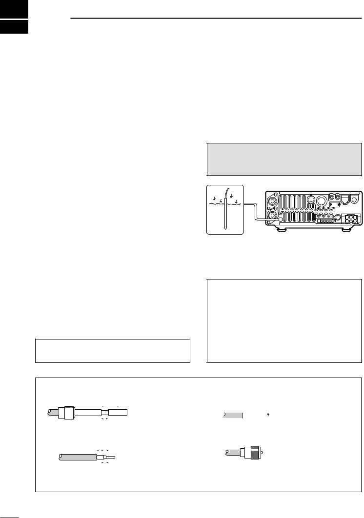
■Antenna
Select antenna(s), such as a well-matched 50 Ω antenna, and feedline. The transmission line should be a coaxial cable. 1.5 : 1 or better of Voltage Standing Wave Ratio (VSWR) is recommended for your required band. Of course, the transmission line should be a coaxial cable.
CAUTION: Protect your transceiver from lightning using a lightning arrestor.
ANTENNA SWR
Each antenna is tuned for a specified frequency range and SWR may be increased out-of-range. When the SWR is higher than approx. 2.0 : 1, the transceiver’s power drops to protect the final transistors. In this case, an optional antenna tuner is useful to match the transceiver and antenna. Low SWR allows full power for transmitting even when using the antenna tuner. The IC-706MKIIG has an SWR meter to monitor the antenna SWR continuously.
PL-259 CONNECTOR INSTALLATION EXAMPLE
|
|
30 mm |
|
|
||||||
|
|
|
|
|
|
|||||
|
|
|
|
|
|
|
|
|
|
|
|
|
|
|
|
|
|
|
|
|
|
|
|
|
|
|
|
|
|
|
|
|
|
|
|
|
|
|
|
|
|
||
|
|
|
|
|
|
|
|
|
|
|
Coupling ring |
10 mm (soft solder) |
|||||||||
|
10 mm |
Soft |
||||||||
|
|
|
|
|||||||
|
|
|
|
|
|
|
||||
|
|
|
|
|
|
|
solder |
|||
|
|
|
|
|
|
|
|
|
|
|
|
|
|
|
|
|
|
|
|
|
|
|
|
|
|
|
|
|
|
|
|
|
|
|
|
|
|
1–2 mm |
|||||
(10 mm ≈ 3⁄8 in)
Slide the coupling ring down. Strip the cable jacket and soft solder.
Strip the cable as shown at left. Soft solder the center conductor.
solder solder Slide the connector  body on and solder it.
Screw the coupling ring onto the connector body.
9
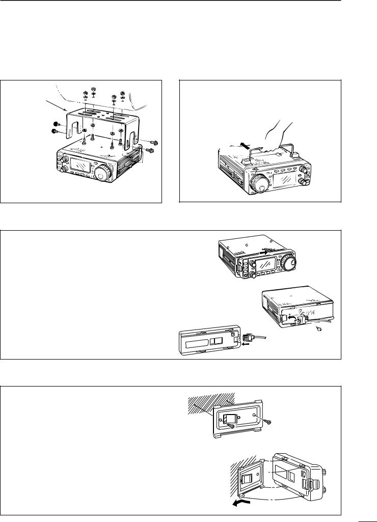
■Installation
DSingle body mounting
MB-62 (optional)
Supplied with 
 the MB-62*

*CAUTION: Non-supplied screws (longer than 8 mm) may damage the internal units.
INSTALLATION AND CONNECTIONS 2
DStand
To raise the stand:
With the transceiver upside down, pull the stand towards the rear panel and then upwards, as illustrated below.
then up
Pull back
DFront panel separation
While pulling the panel release button towards you, slide the front panel to the right (fig. 1).
Attach the optional OPC-581 to the main body and tighten the supplied screw as in fig. 2.
Attach the other end of the OPC-581 to the fig. 1 detached front panel as in fig. 3.
fig. 3
fig. 2
DFront panel mounting
Attach the MB-63 to a flat surface using the two supplied screws (fig. 1).
Fix the detached front panel to the MB-63 as illustrated in fig. 2.
Be careful of the orientation of the MB-63, otherwise, the front panel may become attached in the opposite direction.
fig. 1
fig. 2
10
2 INSTALLATION AND CONNECTIONS
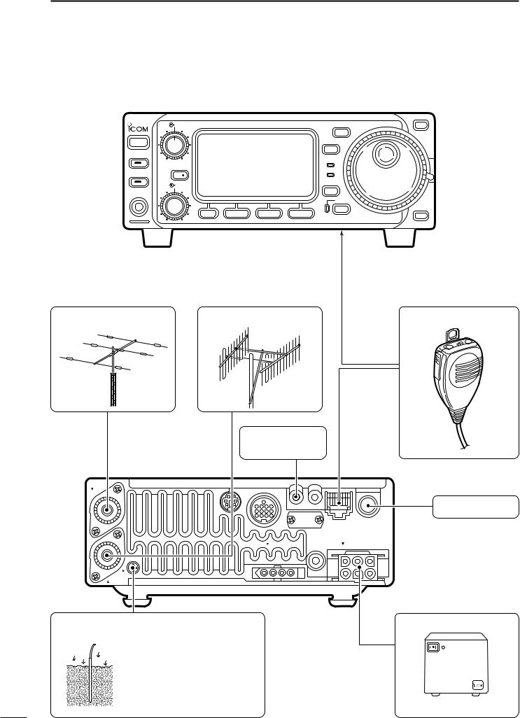
■Required connections
AF RF/SQL HF/VHF/UHF TRANSCEIVER i706MK™G |
MODE |
Y |
BAND
POWER |
TS |
P.AMP/ATT
RX
TX
TUNER/CALL RIT/
SUB
DISPLAY
M-CH SHIFT
PHONES
LOCK
BAND
MENU |
F-1 |
F-2 |
F-3 |
Z |
HF/50 MHz ANTENNA |
2 m ANTENNA |
MICROPHONE (p. 8) |
RTTY TERMINAL |
HM-103 |
|
UNIT (p. 35) |
||
|
ANT 1
CW KEY (p. 33)
KEY
MIC
TUNER |
EXT SP |
DC 13.8V |
GND |
ANT 2 |
GROUND (p. 9)
Use the heaviest gauge wire or strap available and make the connection as short as possible.
Grounding prevents electrical shocks, TVI and other problems.
PS-85
See p. 13 for details.
11

INSTALLATION AND CONNECTIONS 2
■Advanced connections
|
AF |
RF/SQL HF/VHF/UHF TRANSCEIVER i706MK™G |
MODE |
|
|
POWER |
|
TS |
|
|
|
|
||
|
P.AMP/ATT |
|
|
|
|
|
|
RX |
|
|
TUNER/CALL RIT/ |
|
TX |
|
HEADPHONES |
|
|
||
SUB |
|
DISPLAY |
||
M-CH |
SHIFT |
|||
|
|
PHONES
LOCK
MENU |
F-1 |
F-2 |
F-3 |
or
REMOTE (p. 45)
Used for computer control and transceive.
SPEAKER
Selectable with the [PHONE/SPEAKER] switch on the back of the front panel.
|
ACC SOCKET (p. 6) |
COAX ANTENNA |
DATA JACK (p. 37) |
SWITCH |
6-pin mini DIN jack to connect to a |
|
TNC, etc. for packet operation. |
|
ANT 1 |
Y
BAND
BAND
Z
OPC-589 (p. 65)
DESKTOP (p. 64)
MICROPHONE
When using a 50 MHz  antenna separately
since the AH-3 can only be used for the HF bands.
KEY
MIC
TUNER |
EXT SP |
DC 13.8V |
|
|
GND |
ANT 2 |
AH-3 (p. 14)
AH-2b |
EXTERNAL |
SPEAKER (p. 65)
SP-21
12
2 INSTALLATION AND CONNECTIONS
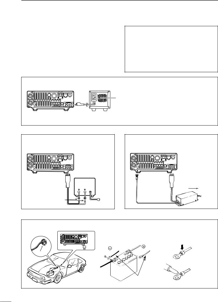
■Power supply connections
Use the optional PS-125 / PS-85 DC POWER SUPPLY when operating the IC-706MKIIG with AC power. Refer to the diagram below for connection.
CAUTION: Before connecting the DC power cable, check the following important items. Make sure:
•The [POWER] switch is OFF.
•Output voltage of the power source is 12–15 V when you use a non-Icom power supply.
•DC power cable polarity is correct.
Red |
: |
positive (+) terminal |
Black |
: |
negative (–) terminal |
CONNECTING THE PS-125 / PS-85 DC POWER SUPPLY
PS-125 / PS-85
DC power socket
DC power cable
Connect to an AC outlet using the supplied AC cable.
Note: When using the PS-125, the IC706MKIIG Europe version complies with EMC directives even if the OPC-639 is not used.
CONNECTING A NON-ICOM |
|
|
DC POWER SUPPLY |
|
|
Transceiver |
|
|
DC power |
|
|
socket |
13.8 V |
20 A |
|
||
Supplied |
Black Red |
|
DC power cable |
|
|
30 A fuses |
|
|
|
|
To AC outlet |
CONNECTING A NON-ICOM
DC POWER SUPPLY (For Europe versions)
Transceiver
[GND] 
639
CONNECTING A VEHICLE BATTERY
Note: Use terminals for NEVER connect to the cable connections.
a 24 V battery.
Crimp
red
black
Grommet
 Solder 12 V
battery
Supplied
DC power cable
13
INSTALLATION AND CONNECTIONS 2
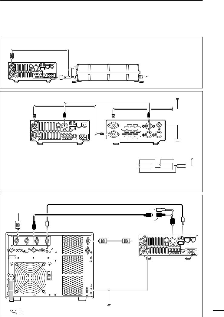
■External antenna tuners and linear amplifier
CONNECTING THE AH-4
|
Coaxial cable |
|
The AH-4 can be used for the HF bands and 50 |
|
|
|
MHz band only. |
|
|
ANT 1 |
(from the AH-4) |
|
AH-4 |
|
|
|
|
||
|
|
|
|
To the AH-2b or |
Transceiver |
|
|
an antenna element |
|
|
|
|
||
CONNECTING THE AT-180 |
ACC cable supplied with the AT-180 |
|
||
Coaxial cable supplied |
HF |
|||
|
|
to 6 m |
||
with the AT-180 |
|
|
|
|
|
|
|
antenna |
|
|
|
|
|
|
|
[ANT 1] |
[ACC] |
AT-180 [ACC] |
one of two |
|
connectors |
|||
IC-706 |
|
[TRANSCEIVER] |
Ground |
Note:
•Turn the IC-706MKIIG’s power OFF when connecting the AT180, otherwise, the CPU may malfunction and the AT-180 may not function properly.
•The OPC-742 is required when using both the AT-180 and a 2 m linear amplifier.
Do not connect [ANT 2] to the AT-180. When using an HF to 2 m wide antenna, use a duplexer between the AT-180 and antenna since 2 m signals do not pass through the AT-180.
HF to 2 m
antenna
Transceiver AT-180
[ANT 1] |
Duplexer |
|
|
[ANT 2] |
|
CONNECTING THE IC-PW1 |
|
|
|
|
||
To an |
Mini-plug cable |
OPC-599 conversion cable |
|
|
||
antenna |
|
|
||||
|
|
|
||||
|
|
ACC cable |
|
|
|
|
|
|
|
|
7-pin side |
|
|
ANT |
ACC-1 |
REMOTE |
|
|
ACC |
REMOTE |
|
|
|
INPUT-1 |
ANT1 |
||
|
|
|
|
|
||
|
|
|
Coaxial cable |
|
|
|
|
|
|
|
GND |
Transceiver |
|
|
|
|
GND |
|
|
|
|
|
IC-PW1 |
|
|
|
|
|
AC outlet (220–240 V) |
|
|
|
14 |
|
|
|
|
|
|
|
|
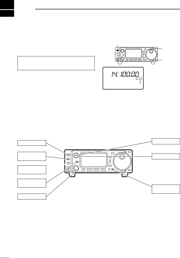
3 FREQUENCY SETTING
■When first applying power (CPU resetting)
Before first applying power, make sure all connections required for your system are complete by referring to section 2. Then, reset the transceiver using the following procedure.
Note: Resetting clears all programmed contents in memory channels and returns all initial set mode and quick set mode contents to their default values.
[POWER]
USB
Make sure the transceiver power is OFF. |
|
|
|
|
|
While pushing [Y] and [Z], push [POWER] to turn |
S1 3 5 7 |
9 20 40 |
60dB |
VFO A |
BLANK |
power ON. |
|
||||
PO |
5 |
10 |
|
CH |
|
• The internal CPU is reset. |
|
||||
M1 SPL A/B A=B |
|||||
•The transceiver displays as shown at right when resetting is complete.
DM1 display selection
If you can’t figure out how to return to the M1 display:
While pushing [MENU], turn power ON.
[Y]
[Z]
The transceiver displays its initial frequency and mode.
■Initial settings
After resetting the transceiver, set controls and switch- |
CCW: counterclockwise |
es as shown in the diagram below. |
|
[POWER]: OFF
[P.AMP/ATT]: OFF (indicator lights out)
[TUNER/CALL]: OFF  (indicator lights out)
[RIT/SUB]: OFF (indicator lights out)
[SHIFT]: Center
Turn power ON, then check the display. If any of the following indicators appear, turn them OFF as follows:
•Tuning step indicators, Z, (SSB, CW or RTTY): Push [TS].
•MHz tuning step indicator, Z, (FM, WFM or AM): Push [TS].
•1 Hz frequency readout (SSB, CW or RTTY): Push and hold [TS].
•Memory mode indicator, MEMO:
Use [(F-3)V/M] in the M2 display (p. 68).
• Split indicator, ä:
Use [(F-1)SPL] in the M1 display (p. 68).
[AF]: Max. CCW
[RF/SQL]: Max. CCW
[LOCK]: OFF (indicator light out)
15
■VFO description
VFO is an abbreviation of Variable Frequency Oscillator, and traditionally refers to an oscillator. The IC-706MKIIG’s VFO can store a frequency and an operating mode.
You can call up a desired frequency to a VFO with the memo pad-read switch (p. 42) or with the memory transfer switch (p. 42). You can also change the frequency with the main dial and select an operating mode with the [MODE] switch or call up previously accessed frequency and modes with the band stacking register (p. 19).
The IC-706MKIIG has two VFOs, specially suited for split frequency operation. The VFOs are called VFO A and VFO B. You can use the desired VFO to call up a
FREQUENCY SETTING 3
frequency and operating mode for operation.
VFO |
Select |
MODE |
|
SWITCH |
|||
|
|
||
|
USB |
|
|
|
|
Change |
|
|
|
VFO A |
|
CH |
DIAL |
|
M1 SPL A/B A=B |
|||
|
Transfer |
Transfer |
|
Transfer |
|
||
MEMORY |
BAND |
||
MEMO PAD |
|||
CHANNEL |
21.295 MHz |
||
28.025 MHz |
7.001 MHz |
||
|
|||
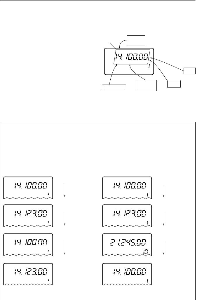
• The differences between VFO and memory mode
VFO MODE
Each VFO shows a frequency and operating mode. If the frequency or operating mode is changed, the VFO automatically memorizes the new frequency or operating mode.
When the VFO is selected from another VFO or memory mode, the last-used frequency and operating mode for that VFO appear.
[EXAMPLE]
USB |
VFO is selected. |
VFO A
 CH
CH
USB |
The frequency is changed. |
|
VFO A
 CH
CH
USB |
Memory mode is selected. |
MEMO  CH
CH
USB |
VFO is selected again. |
VFO A
 CH
CH
MEMORY MODE (pgs. 39–42)
Each memory channel shows a frequency and operating mode like a VFO. Even if the frequency or mode is changed, the memory channel does not memorize the new frequency or memory mode.
When a memory channel is selected from another memory channel or VFO mode, the memorized frequency and operating mode appear.
[EXAMPLE]
USB |
Memory channel 1 is |
|
selected. |
MEMO |
CH |
USB |
The frequency is changed. |
|
|
MEMO |
CH |
USB |
Another memory channel |
|
is selected. |
MEMO |
CH |
USB |
Memory channel 1 is |
|
selected again. |
MEMO |
CH |
Changed frequency (14.123 MHz) appears.
Changed frequency (14.123 MHz) does not appear and memorised frequency (14.100 MHz) appears instead.
16
3 FREQUENCY SETTING
■Frequency setting
• Band selection
All HF ham bands, the 50 MHz band, the 144 MHz band and a general coverage receiver band are included in the IC-706MKIIG.
Push [(Y)BAND]/[(Z)BAND] to select the desired band.
•Pushing [(Y)BAND]/[(Z)BAND] continuously scrolls through the available bands.
Note: The band stacking register can also be used to select bands. Refer to p. 19.
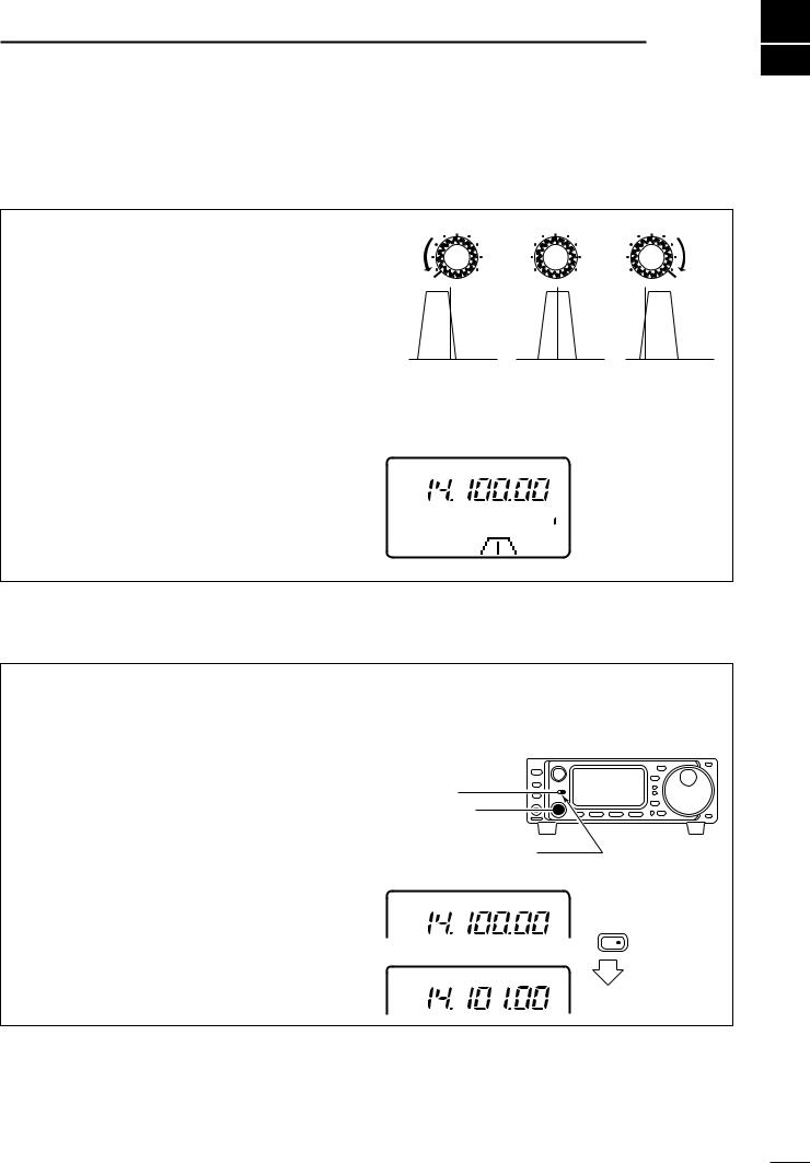
• Programmable tuning steps
Programmable tuning steps are available to suit your operating requirements.
These tuning steps are:
•Independently selectable for each mode
•Selectable from 0.01 (FM/WFM/AM only), 0.1, 1, 5, 9, 10, 12.5, 15, 20 and 100 kHz
Push [TS] one or more times until the programmable tuning step indicator, “Z,” appears above the 1 kHz digit.
•Rotating the main dial changes the frequency according to the set tuning step.
Push [TS] for 2 sec. while the programmable tuning step indicator appears to enter the tuning step
selection mode.
•Rotate DIAL appears.
Rotate the main dial to set the desired tuning step.
•Change the mode and select tuning steps for other modes, if desired.
Push [TS] to exit the tuning step selection mode.
Rotate the main dial to change the frequency according to the set tuning step.
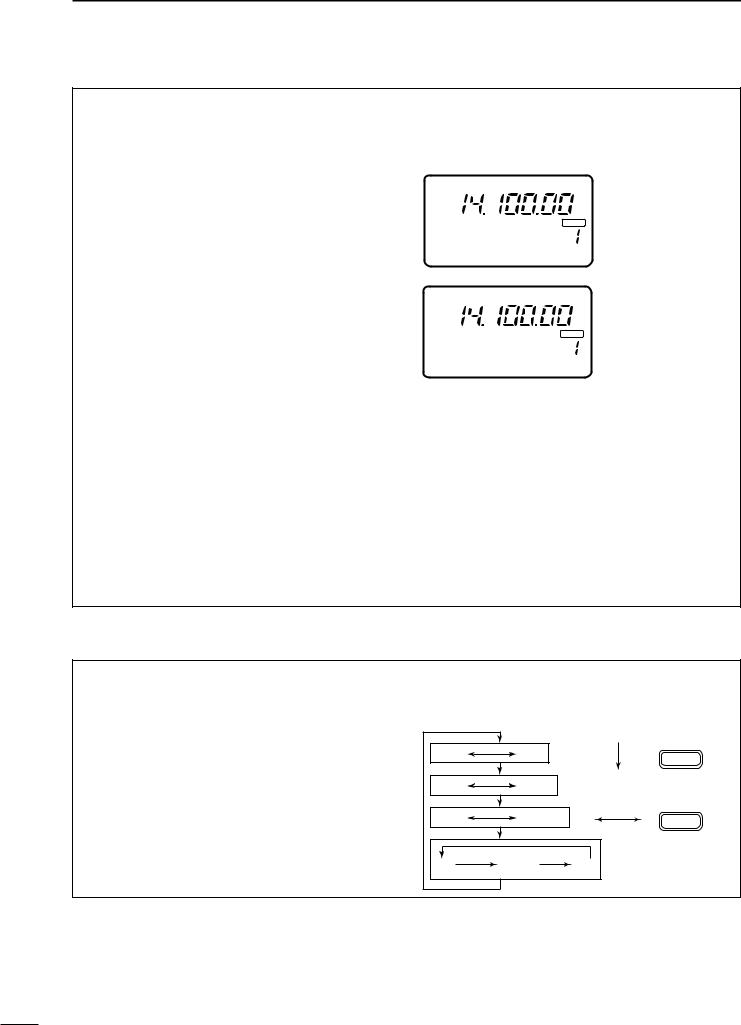
• 1 Hz and 10 Hz tuning steps
When neither the quick tuning step or programmable tuning step, “Z,” appear, rotating the main dial changes the frequency in increments of 1 or 10 Hz. These tuning steps are only available in SSB, CW and RTTY modes.
Select SSB, CW or RTTY mode if necessary.
Push [TS] for 2 sec. to toggle between the 1 and 10 Hz step settings.
•When the 1 Hz step is selected, the 1 Hz digit appears in the frequency indication; when the 10 Hz step is selected, the 1 Hz digit disappears from the frequency indication.
LSB |
FM |
Z
USB
|
Z |
USB |
USB |
|
USB
S1 3 5 7 9 |
20 40 |
60dB |
VFO A |
PO |
5 |
10 |
CH |
M1 SPL A/B A=B
USB
Programmable tuning step indicator
10 kHz tuning step is selected for USB operation.
RotateDIAL
USB |
|
Rotating the main dial |
|
changes the frequency |
|
|
|
|
|
|
in 10 Hz steps. |
|
|
VFO A |
Push |
TS |
for 2 sec. |
USB |
|
Rotating the main dial |
|
changes the frequency |
|
|
|
|
|
|
in 1 Hz steps. |
|
|
VFO A |
17
FREQUENCY SETTING 3
• 1 MHz quick tuning step
The quick tuning step function allows you to change the frequency in 1 MHz steps when rotating the main dial. This function is only available in FM, WFM and AM modes.
Select FM, WFM or AM mode if necessary.
Push [TS] momentarily to toggle between the 1 MHz tuning step and the programmable tuning step.
•“Z” appears above the 1 MHz indicator when the 1 MHz tuning step is selected.
•When the 1 MHz tuning step is selected, slow rotation of the main dial changes the frequency in 1 MHz steps and fast rotation of the main dial changes the frequency in 5 MHz steps.
Quick tuning step
indicator
FM
|
Rotating the main dial |
|
changes the frequen- |
FM |
cy in 1 MHz steps. |
[TS] SWITCH FLOW CHART |
|
|
|
|
SSB/CW/RTTY modes |
|
Any mode |
FM/WFM/AM modes |
|
|
|
Programmable step tuning |
|
|
10 Hz tuning |
|
(100 Hz –100 kHz) |
|
1 MHz tuning |
USB |
|
USB |
|
FM |
|
TS |
|
|
TS |
2 sec. |
momentarily |
TS |
2 sec. |
momentarily |
|
|
|
|
|
2 sec. |
|
momentarily |
|
|
|
|
|
|
|
USB |
|
USB |
|
|
1 Hz tuning |
|
|
|
|
|
|
Rotate DIAL |
|
|
|
|
Selectable for each mode. |
|
|
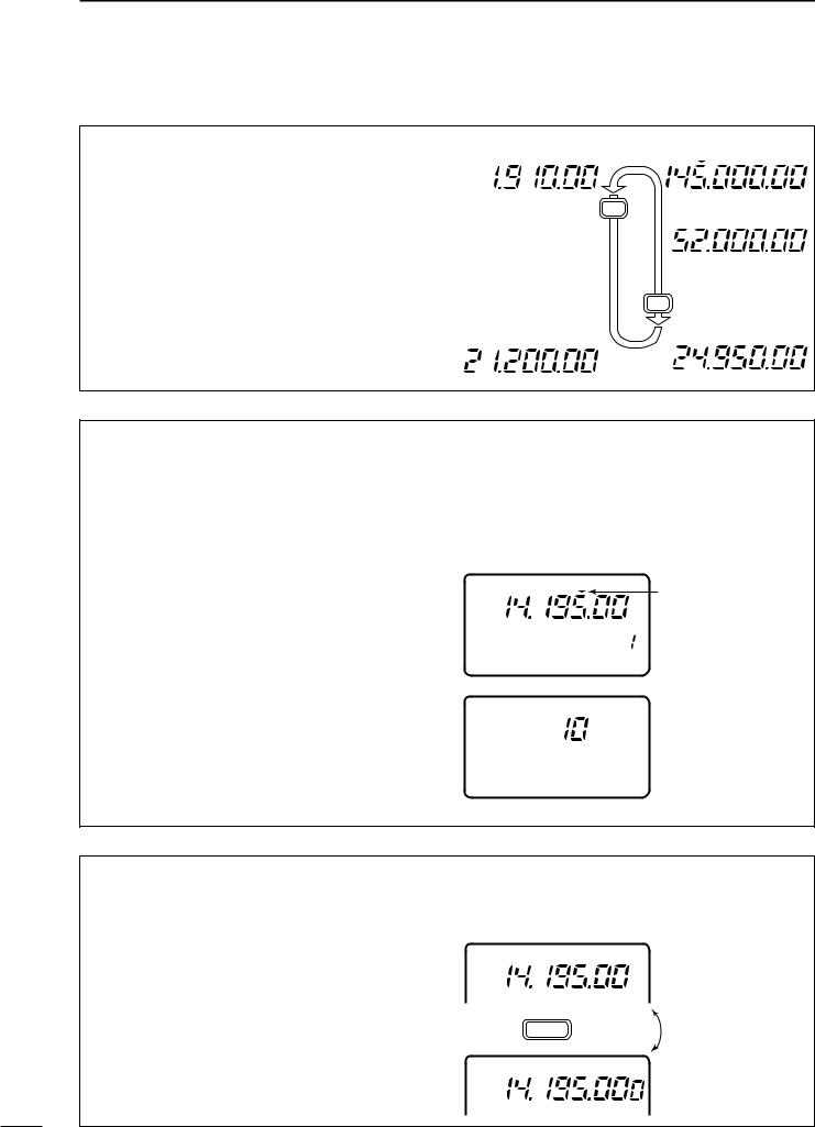
• Sub dial function
The sub dial function allows you to change the operating frequency using the [M-CH] control. This gives you more control in tuning since the [M-CH] knob is detented—each click changes the frequency according to the set tuning step. This function is always available in FM, WFM and AM modes. However, in SSB, CW and RTTY modes, the set mode item “Sub dial function,” must be set to “FrEq.”
Push [RIT/SUB] to turn the sub dial function ON.
•The [SUB] indicator lights green; if it lights red, the RIT function is activated—sub dial function must be set in initial set mode in this case.
Rotate [M-CH] to change the operating frequency according to the set tuning steps.
Push [RIT/SUB] again to turn the function OFF.
•The [SUB] indicator turns off.
[SUB] switch [M-CH] control
Indicator lights green while the sub dial function is activated.
RIT/ SUB
18
3 FREQUENCY SETTING
• Quick band change function
The quick band change function automatically stores the last frequency and mode used for each band in a band stacking register. This is convenient for contest operation, etc. The tables below show the quick band change default settings for each band.
Select S3.
•Push [DISPLAY] when M or G is displayed.
•Push [MENU] twice to select S3.
Push [F-1]–[F-3] to select a band stacking register.
•The default settings for [F-1]–[F-3] are 7, 144 and 430 MHz bands, respectively.
To change the settings for [F-1]–[F-3] from their defaults, push [F-1]–[F-3] for 1 sec. one or more times to until the desired band appears in the display above the corresponding switch.
•The last-used frequency and mode for the selected band are displayed.
BAND |
FREQUENCY |
MODE |
|
|
|
|
|
1.9 MHz |
1.91000 |
MHz** |
CW |
|
|
|
|
3.5 MHz |
3.56000 |
MHz |
LSB |
|
|
|
|
7 MHz |
7.06000 |
MHz |
LSB |
|
|
|
|
10 MHz |
10.13000 MHz |
CW |
|
|
|
|
|
14 MHz |
14.10000 |
MHz |
USB |
|
|
|
|
General* |
15.10000 |
MHz |
USB |
|
|
|
|
*General refers to the general coverage receiver (GEN in the display) and the range varies according to version.
** 1.83000 MHz for Italy version (#10,#20).
|
|
USB |
|
|
|
|
|
|
|
Display shows the |
||||
|
|
|
|
|
|
|
|
|
|
default bands for the |
||||
|
|
|
|
|
|
|
VFO A |
BLANK |
quick band change |
|||||
S1 3 |
5 |
7 9 |
20 |
40 |
60dB |
function. |
|
|||||||
|
|
|||||||||||||
|
|
|
|
|
|
|
|
|
|
|
||||
PO |
|
|
5 |
|
10 |
|
|
CH |
|
|
|
|
||
S3 |
|
7 |
|
144 |
430 |
|
|
|
|
|||||
|
|
USB |
|
|
|
|
|
|
|
Display shows [F-2] |
||||
|
|
|
|
|
|
|
|
|
|
has been changed from |
||||
|
|
|
|
|
|
|
VFO A |
BLANK |
its default of the 50 MHz |
|||||
S1 3 |
5 |
7 9 |
20 |
40 |
60dB |
band to the general |
||||||||
|
||||||||||||||
|
|
|
|
|
|
|
|
|
|
|||||
PO |
|
|
5 |
|
10 |
|
|
|
CH |
receiver band. |
|
|||
S3 |
|
7 |
|
GEN 144 |
|
|||||||||
|
|
|
|
|
|
|
|
|
|
|||||
|
BAND |
|
|
|
|
|
FREQUENCY |
|
MODE |
|||||
|
|
|
|
|
|
|
|
|
|
|
||||
18 MHz |
|
|
|
|
|
|
18.15000 |
MHz |
|
USB |
||||
|
|
|
|
|
|
|
|
|
|
|
||||
21 MHz |
|
|
|
|
|
|
21.30000 |
MHz |
|
USB |
||||
|
|
|
|
|
|
|
|
|
|
|
||||
24 MHz |
|
|
|
|
|
|
24.95000 |
MHz |
|
USB |
||||
|
|
|
|
|
|
|
|
|
|
|
||||
28 MHz |
|
|
|
|
|
|
28.60000 |
MHz |
|
USB |
||||
|
|
|
|
|
|
|
|
|
|
|
||||
50 MHz |
|
|
|
|
|
|
50.10000 |
MHz |
|
USB |
||||
|
|
|
|
|
|
|
|
|
|
|||||
144 MHz |
|
|
|
|
|
145.00000 |
MHz |
|
FM |
|||||
|
|
|
|
|
|
|
|
|
|
|||||
430 MHz |
|
|
|
|
|
433.00000 |
MHz |
|
FM |
|||||
|
|
|
|
|
|
|
|
|
|
|
|
|
|
|
■Mode selection
The following modes are available in the IC706MKIIG:
SSB (LSB/USB), CW, CW-å (CW reverse), FM, WFM (receive only), AM, RTTY and åRTTY (RTTY reverse).
To select the desired mode of operation push [MODE] one or more times, then push [MODE] for 2 sec., if necessary. See the diagram at right for the order of selection.
• The selected mode is indicated in the function display.
Note: If a desired mode cannot be selected, it may be hidden using Initial Set mode (p. 50).
OPERATING MODE SELECTION
USB |
LSB |
Push |
|
MODE |
|||
|
|
||
CW |
CWå |
momentarily |
|
|
RTTY |
åRTTY |
Push |
MODE |
||
|
|
for 2 sec. |
FM |
WFM |
AM |
19
RECEIVE AND TRANSMIT 4
■Functions for receive
DIF shift function
The IF shift function electronically changes the passband frequency of the IF (intermediate frequency) and cuts out higher or lower frequency components of the IF to reject interference. The function shifts the IF frequency up to ±1.2 kHz in 15 Hz steps in SSB/CW/RTTY modes and up to ±250 Hz in 3 Hz steps in CW-ã/RTTY-ã modes. The IF shift is not available in FM and AM modes.
Adjust the [SHIFT] control for a minimum interference signal level.
•The audio tone may be changed while the IF shift is in use.
Set the shift control to its center position when there is no interference.
• Graphic display
The IF shift is displayed graphically (for about 1 sec.) each time the shift control is rotated.
M-CH 
 SHIFT M-CH
 SHIFT M-CH
 SHIFT
SHIFT
Shifts low |
Center |
Shifts high |
USB
S1 3 5 7 9 20 40 60dB VFO A
 CH
CH
DRIT function
The RIT (Receive Incremental Tuning) function compensates for off-frequencies of communicating stations. The function shifts the receive frequency up to ±9.99 kHz in 10 Hz steps without moving the transmit frequency. The [SUB/RIT] switch in Initial Set Mode must be set to RIT mode in advance (p. 51).
Push [RIT].
•The [RIT] indicator lights red.
Rotate the [M-CH] control to cancel the off-fre- quencies.
•The transmit frequency is not shifted.
To cancel the RIT function, push [RIT] again.
•The [RIT] switch indicator goes out.
• Calculate function
The shift frequency of the RIT function can be added/subtracted to the displayed frequency.
While the RIT indicator is lit, push and hold [RIT] for 2 sec.
Note: The RIT function is not available in FM, WFM or AM modes regardless of the Initial Set mode setting (p. 51).
[RIT] switch [M-CH] control
Indicator lights red while
RIT function is activated.
USB
Push for 2 sec.
USB
20
 Loading...