


INSTRUCTION MANUAL
C50/C75
1-800-547-5740 • Fax: (503) 643-6322 www.ueitest.com • email: info@ueitest.com
Introduction
The C50 / C 75 enables HVAC professionals to accurately test and service all residential combustion appliances. The extra large backlit LCD displays two p a rameters at one time. Easily choose the desired combustion para m e t e r with the rotary selector. The optional printer allows you to print your readings to document your test results.
Features include
•Choose combustion parameter with a rotary selector
•Measure flue temperature and oxygen (C75: also carbon monoxide)
•Calculates carbon dioxide, gross & net efficiency, and excess air ( C 75: also carbon monoxide air free)
•Large backlit LCD, 2 line display
•Protected boot with an integral magnet
•1 ppm accuracy
•Infrared printer port
•User programmable header
•16 position memory
Safety Notes
Before using this meter, read all safety information carefully. In this manual the word "WARNING" is used to indicate conditions or actions that may pose physical hazards to the user. The word "CAUTION" is used to indicate conditions or actions that may damage this instrument.
 WARNING!
This analyzer extracts combustion gases that may be toxic in relatively low concentrations. These gases are exhausted from the back of the instrument. This instrument must only be used in well-ventilated locations. It must only be used by trained and competent persons after due consideration of all the potential hazards.
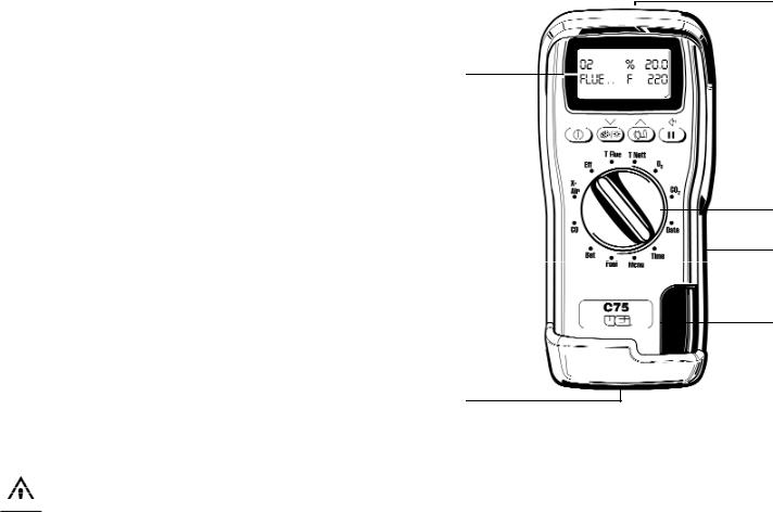
Controls and Indicators
1.Display
2.Infrared Printer Port
3. ON/OFF: Turns analyzer ON and OFF.
4. Print/Back-Light: Print data (Press and hold until
“PRINTING” appears) / Hold to toggle back-light ON or OFF.
5. Pump/Top Line: Turns pump ON and OFF / Hold to scroll through top line display (also selectable through menu).
6.| | Hold/Store: Freezes reading on display. Entire display flashes. Press and hold for 2 seconds to store data in memory.
7.Rotary Selector
8.Particle Filter
9.Water Trap
10.Analyzer Connections
2
1
 5 3
5 3 
 6 4
6 4 
7
8
9
10
Main Display Parameters
O 2 : |
Oxygen reading in percentage (%). |
T f : |
Temperature is measured by the flue gas probe in Centigrade |
|
or Fahrenheit. Will show ambient temperature after fresh air |
|
calibration and “- - - -” if the flue probe is disconnected. |
C O : |
Carbon Monoxide reading displayed in ppm (parts per |
|
million). “----” is displayed if there is a fault with the CO |
|
sensor or the instrument has not set to zero correctly, |
|
switch off instrument and try again. |
C O a : |
Carbon Monoxide air-free reading referenced to an oxygen |
|
level of 0%. Do not confuse this reading with the actual CO |
|
reading as detailed above. |
C O2: |
Carbon Dioxide calculation determined by the type of fuel. |
|
This only shows a reading when a combination test is being |
|
carried out. “- - - -” is displayed while in fresh air. |
∆T: |
Net temperature calculated by deducting the AMBIENT |
|
(or INL ET) temperature from the measured FL UE |
|
t e m p e rature. Displays in either Centigrade (˚C) or Fahrenheit |
|
(˚F) and will display “- - - -” if the flue probe is not connected. |
EFF (G): Combustion efficiency calculation displayed in percentage. Gross (G) or Net (N) can be set (see MENU). The calculation is determined by the fuel type and uses the calculation in British Standard BS845. The efficiency is displayed during a combustion test, “- - - -” is displayed while in fresh air.
XAIR%: Excess air calculated from the measured oxygen and type of fuel used. Displays reading during a combustion test. “- - - -” is displayed while in fresh air.
A MB : Boiler air INL ET t e m p e rature used to calculate the NET t e m p e ra t u r e
C50/C75-MAN |
P. 1 |
C O / C O 2 : The CO / CO2 ratio is the ratio of measured CO divided by calculated CO 2 .
It gives an indication of:
•H ow good a gas sample the instrument is reading
•H ow clean the boiler is running
For example: A new or clean domestic boiler will display a ratio of less than 0.004, a unit in need of cleaning 0.004 - 0.008 and a unit in need of major overhaul will show greater than 0.008.
This only shows a reading when a combustion test is being carried out. “- - - -” is displayed while in fresh air.
:Displays the approximate battery level as follows:
•Full battery level
•Battery at 75 %
•Battery at 50 %
•Battery at 25 %
When the display flashes this, it indicates the batteries are at less than 10% of charge and should be replaced, readings may be affected if the analyzer is used with low power batteries.
DATE : Date shown as day, month and year. The order can be changed using the menu function. Date is stored with a combustion test.
TIME : The time is shown in hours and minutes, these details are stored with each combustion test.
NOT E : When changing the batteries on the instrument the memory will store the date and time for up to one minute,
if outside this time it may be necessary to re-enter the details.
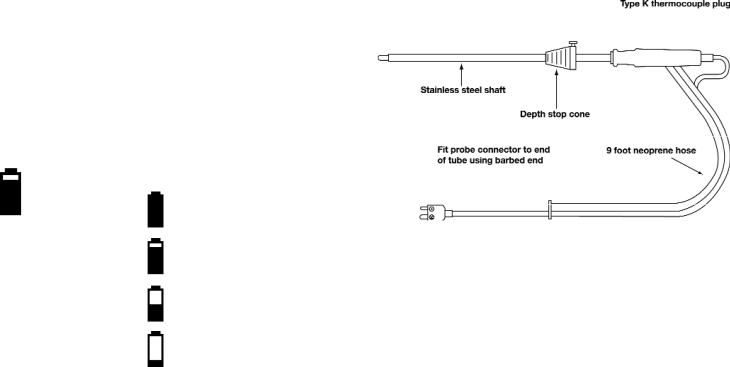
Probe Configuration
Operating Instructions
Before Use Each Time
•The particle filter is not dirty
•The water trap and probe line are empty of water
•All hose and thermocouple connections are properly made
•The flue gas probe is sampling ambient FRESH air
•The water trap is fitted correctly to the instrument
•The flue temperature plug is connected
•The inlet temperature probe is connected if required
Switch ON the instrument by pressing “  “.
“.
After switch-on, the analyzer will scroll through the following information while performing a zero countdown:
•Currently Set Date
•Currently Set Time
•Remaining Battery Level
•Fuel Selected
•Model and Analyzer Firmware Level
NOTE: The count begins at 59 seconds, and will display the parameter selected with the rotary knob when the sensors are detected as stable. If the analyzer will not auto-zero, the sensors are in need of replacement and the unit should be returned to the authorized service center.
C50/C75-MAN |
P. 2 |

Analyzer Connections
Flue (Tf) temperature |
Mains adapter socket |
Flue gas inlet |
socket |
|
|
Water trap drain plug
NOTE: Take care when inserting the temperature probes as the pins are polarized. Insert with the smaller pin (+) to the right. A view of the sockets is shown below.
Automatic Calibration
During this sequence the analyzer pumps fresh air into the Oxygen and CO (C75 only) sensors to allow them to be set to 20.9% and zero respectively. See “Setting Inlet Temperature) for information on options.
Changing the Display
The parameters on the first line display are selected from the following using the pump key (press and hold for display item to change). Certain items are available on the lower display by selecting with the rotary dial.
Display |
Item |
Note |
|
|
NAT GAS* |
Fuel selected |
Fuel indicator |
|
|
|
|
• |
NAT Gas |
Natural Gas |
|
|
• |
Propane |
|
|
|
• |
Butane |
|
|
|
• |
L Oil |
Light Oil |
|
|
• |
LPG |
Liquid Petroleum Gas |
R 0.0000 |
CO/CO2 ratio |
Measured CO divided by calculated CO2 |
||
P 0.00 |
Poison index |
CO/CO2 ratio x 100 |
||
AMB xx |
Ambient temperature |
Either instrument internal temperature or |
||
|
(used as inlet |
stored inlet temperature set during zero |
||
|
temperature for ∆T) |
countdown |
|
|
COa |
CO air free reading |
CO reading adjusted to 0% O2 (C75 only) |
||
O2 |
O2 Ref |
O2% reference value to calculate readings |
||
|
|
normalized to a set O2 level. |
||
hh:mm:ss* |
Time |
Currently set time |
|
|
MM/DD/YY* |
Date |
Currently set date |
|
|
CO2* |
Carbon Dioxide |
Calculated CO2 value |
||
O2* |
Oxygen |
Measured O2 value |
||
∆T* |
T Nett |
Difference between Flue Temp and Ambient |
||
|
|
(or inlet temperature) |
||
TF* |
T Flue |
Measured Flue Temperature |
||
η (G, N or C)* |
Efficiency |
Displays calculated efficiency when O2 |
||
|
|
values are less than 18%. Displayed as |
||
|
|
ηN, ηG or ηC as selected by the user. |
||
|
Losses (C50 only) |
Losses calculated from Oxygen and type of |
||
|
|
fuel. Displays reading during a combustion |
||
|
|
test. “----” is displayed while in fresh air. |
||
CO* |
Carbon Monoxide |
Displays Carbon monoxide values in PPM as |
||
|
(C75 only) |
CO. Display value in mg/m3 as COm. |
||
* |
Battery level |
|
|
|
|
|
|
|
|
λ* |
Excess Air |
|
|
|
*Available on the second line of the display.
Setting Inlet Temperature
During the automatic calibration sequence the burner INLET (Ti) temperature used in the NET temperature calculation is stored in the analyzer. There are two methods of storing the INLET temperature.
A.Without the flue probe connected temperature inside the analyzer is used (ambient temperature).
B.If the flue probe is connected the temperature of the probe tip is used. This can be useful when the temperature of the air entering the burner is different than the ambient temperature of the room.
NOTE: On ducted inlets, insert the probe tip into the inlet air during the zero countdown. The analyzer will then store this temperature as the ambient (inlet) for use in efficiency calculations. Do not sample flue gas during the zero countdown.
WARNING!
If the INLET temperature is set incorrectly, then errors will be made in the calculation of net temperature and efficiently.
Sampling the Flue Gas
Once the automatic calibration procedure has been completed and the specific fuel has been selected (see menu options) the probe can be inserted into the desired sampling point.
It is recommended that the sampling point be located at least two flue diameters downstream of any bend, as close to the source as possible, and that the probe tip is in the center of the flue. With balanced flues and other domestic units the probe should be positioned far enough into the flue so that no air can “back flush” into the probe.
The probe depth stop cone provided with the instrument allows the probe to be used in holes whose diameters range from 1/4 to 4/5 inch (6 mm to 21 mm).
The standard probe is rated at 1112˚F (600˚C).
TIP: To conserve battery power, switch off the pump when you are not taking a measurement. To turn pump ON or OFF press “  “.
“.
View data and rotate the dial to see flue changes as you make adjustments. Press “HOLD” first to freeze or store the readings before printing.
C50/C75-MAN |
P. 3 |
 Loading...