


ICRW12CEIV
ICC ICRW12CEIV, ICRW11TOIV, ICRW11JCWH, ICRW11CEWH, ICRWR13SWH User Manual
...
Raceway System
INSTALLATION INSTRUCTIONS
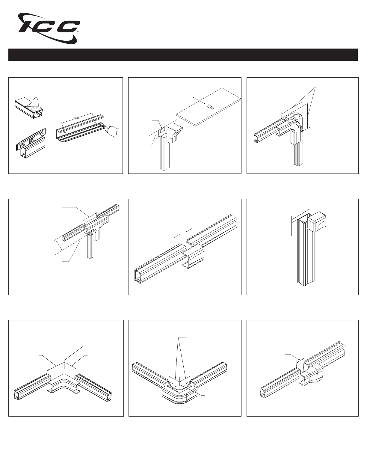
Figure 1: Secure raceway with included adhesive
backing or drill holes for screw mounting. Use a level
to align raceway.
Tee
Raceway Placement
With Base
5-1/2” min.
5-3/4” max.
Without Base
3” min.
5-3/4” max.
Ceiling entry
Max cut out:
ICRW11CExx - 3/4” diameter
ICRW12CExx - 1-3/8” diameter
ICRW13CExx - 1-3/4” diameter
Ceiling
1/2” min.
2-1/4” max.
Figure 2: Routes cable from ceiling into the raceway
Joint Cover
0” min.
1-1/4” max.
Flat Elbow
Raceway Placement
With Base
3-27/32” min.
4” max.
Without Base
2-1/2” min.
4” max.
Figure 3: 90˚ is used for right angle turns on the same
surface. Base is slotted for screw down mounting, if
necessary.
End Cap
Cap will
extend up to
3/16”
from raceway
Raceway Placement
With Base
3-25/32” min.
4” max.
Without Base
2-1/2” min.
4” max.
Figure 4: Used to branch raceway runs. Base is slotted
for screw down mounting, if necessary.
Inside Wall Corner
1-3/4” min.
2-1/2” max.
1-3/4” min.
2-1/2” max.
Figure 7: Used for right angle turns around internal corners
Figure 5: Used to cover joint where two sections of
raceway come together
Outside CornerInside Corner Cover
Raceway Placement
With Base Without Base
2” min. 1” min.
2-1/4” max. 2-1/4” max.
Outside Wall Corner
Figure 8: Used for right angle turns around external
corners. Base is slotted for screw down mounting
Figure 6: Used for closing the open end of raceway
Reducer
0” min.
2-1/4” max.
Figure 9: Used to transition from one size of raceway
to another
888-ASK-4ICC csr@icc.com icc.com
© Copyright 2011, ICC. ICC and ICC logo are registered trade name and trademark. All rights reserved. MSR-0334-RevC
 Loading...