


 Loading...
IBM TotalStorage 3581 Tape Autoloader |
|
Models L28/L38/L3H and F28/F38/F3H |
Setup, Operator, and Service Guide
GA32-0470-01
IBM TotalStorage 3581 Tape Autoloader |
|
Models L28/L38/L3H and F28/F38/F3H |
Setup, Operator, and Service Guide
GA32-0470-01

Note!
Before using this information and the product it supports, read the information in “Safety and Environmental Notices” on page xv and “Notices” on page 293.
To ensure that you have the latest publications, visit the web at http://www.ibm.com/storage/support/lto, select your product, and click ″Documentation″.
Second Edition (March 2005)
| This edition applies to the IBM TotalStorage Ultrium Tape Autoloader 3581 Models L28/L38/L3H and F28/F38/F3H Setup,
| Operator, and Service Guide and to all subsequent releases and modifications until otherwise indicated in new | editions.
| The IBM« TotalStorage Ultrium Tape Autoloader 3581 Models L28/L38/L3H and F28/F38/F3H offer a 3-year
| parts-only warranty and are supported by the Customer Replaceable Unit (CRU) process. For details about the CRU | process and customer responsibilities, see the warranty that is included in the back of this document.
© Copyright International Business Machines Corporation 2004, 2005. All rights reserved.
US Government Users Restricted Rights – Use, duplication or disclosure restricted by GSA ADP Schedule Contract with IBM Corp.

|
Read This First |
|
|
|
Accessing Online Technical Support |
|
For online Technical Support for your Autoloader, visit: |
|
http://www.ibm.com/storage/support/lto |
|
|
| |
Summary of Changes |
| |
This section summarizes changes to this publication. A vertical line in the left |
| |
margin indicates each change. |
| |
Second Edition (March 2005) |
| |
v Clarified the steps for determining the proper rack holes to use when installing |
| |
the autoloader in a rack. |
| |
v Modified the Operator Guide section by updating procedures, menus, and |
| |
artwork, as necessary, to reflect changes in the microcode. |
| |
v Changed the sequence of steps in the Configuration section in an effort to |
| |
streamline the configuration procedure. |
| |
v Expanded and restructured the Troubleshooting section. |
| |
v Added new service procedures to the Appendices. |
|
|
|
Registering for My Support |
| |
My Support registration provides email notification when new firmware levels |
| |
have been updated and are available for download and installation. To register for |
| |
My Support, visit the web at http://www.ibm.com/support/mySupport. |
|
|
|
Sending IBM Your Feedback |
|
Your feedback is important in helping IBM® provide accurate and useful |
|
information. If you have comments or suggestions for improving this publication, |
|
send your comments by: |
|
v E-mailing IBM: |
|
– Internet or IBMLink™ from US: starpubs@us.ibm.com |
|
– IBMLink from Canada: STARPUBS at TORIBM |
Include the following information in your e-mail:
–Exact publication title
–Form number (for example, GA32–1234–02) or part number (located on the back cover of the publication)
–Page numbers to which you are referring
v Using the Readers’ Comments form at the back of this publication
vMailing your comments to:
International Business Machines Corporation Information Development
Department GZW 9000 South Rita Road
Tucson, AZ 85744-0001 USA
© Copyright IBM Corp. 2004, 2005 |
iii |
iv IBM 3581 Autoloader Models L28/L38/L3H and F28/F38/F3H Setup, Operator, and Service Guide

Contents
|
Read This First . . . . . . . . . |
. |
. iii |
Server (Host) Attachment. . . . . . . . . |
. |
14 |
|
Accessing Online Technical Support . . . |
. . |
. iii |
Supported Servers (Hosts) and Operating |
|
|
| |
Summary of Changes . . . . . . . . |
. . |
. iii |
Systems . . . . . . . . . . . . . |
. |
14 |
| |
Second Edition (March 2005). . . . . |
. . |
. iii |
Supported Device Drivers . . . . . . . |
. |
15 |
|
Registering for My Support . . . . . . |
. . |
. iii |
TapeAlert Support . . . . . . . . . . . |
. |
15 |
|
Sending IBM Your Feedback . . . . . . |
. . |
. iii |
Specifications . . . . . . . . . . . . . |
. |
15 |
Figures . . . . . . . . . . . . . . . ix Tables . . . . . . . . . . . . . . . xiii Safety and Environmental Notices . . . xv
Danger Notice . . . . . . . . . . . |
. |
. xv |
Caution Notice . . . . . . . . . . . |
. |
. xv |
Laser Safety and Compliance . . . . . . . |
|
. xvi |
Class I Laser Product . . . . . . . . . |
|
. xvi |
Intended Use . . . . . . . . . . . . |
|
. xvi |
Safeguards . . . . . . . . . . . . . . xvi |
||
Precautions . . . . . . . . . . . . . . xvii |
||
Safety Inspection Procedure . . . . . . . |
|
. xvii |
| 3581 Library ac Grounding Inspection . . . . |
|
. xvii |
End of Life (EOL) Plan . . . . . . . . . |
|
. xviii |
|
About This Guide . . . . |
. . |
. . . . xix |
||
| |
Related Publications . . . . . |
. . |
. . . |
. xix |
|
3581 Autoloader Publications . |
. . |
. . . |
. xix |
||
| |
Redbooks . . . . . . . . |
. . |
. . . |
. xix |
|
| |
Device Driver Publications . |
. . . |
. . |
. |
. xx |
| |
Safety Publications . . . . |
. . . |
. . |
. |
. xx |
| |
SCSI Publications . . . . |
. . . |
. . |
. |
. xx |
| |
Online Support . . . . . . |
. . . |
. . |
. |
. xx |
| |
Autoloader Firmware . . . |
. . . |
. . |
. |
. xx |
| |
IBM Online Support . . . |
. . . |
. . |
. |
. xx |
| |
IBM Publications Center . . |
. . . |
. . |
. |
. xx |
| |
IBM Redbooks . . . . . |
. . . |
. . |
. |
. xx |
| |
Device Drivers . . . . . |
. . . |
. . |
. |
. xx |
| |
Media and Supplies . . . . |
. . |
. . . |
. |
xxi |
|
Part 1. Setup Guide . . . . . . |
. |
. |
. |
1 |
|
Product Description . . . . . . |
. |
. |
. |
3 |
|
Product Features . . . . . . . . . . |
. |
. |
. |
4 |
|
Standard Features . . . . . . . . |
. |
. |
. |
4 |
|
Optional Features. . . . . . . . . |
. |
. |
. |
6 |
|
Component Descriptions . . . . . . . |
. |
. |
. |
7 |
|
Front Panel Components . . . . . . |
. |
. |
. |
7 |
|
Interior Components. . . . . . . . |
. |
. |
. |
8 |
|
Rear Panel Components . . . . . . |
. |
. |
. |
10 |
|
Media . . . . . . . . . . . . . |
. |
. |
. |
11 |
| |
Tape Drive Performance . . . . . . . |
. |
. |
. |
12 |
Interfaces . . . . . . . . . . . . |
. |
. |
. |
12 |
|
| |
SCSI Differential (HVD) . . . . . . |
. |
. |
. |
12 |
| |
SCSI Differential (LVD) . . . . . . |
. |
. |
. |
13 |
| |
Fibre Channel Supported Topologies . . |
. |
. |
. 13 |
|
Installation . . . . . . . . . . . . . 17
|
Step 1. Unpack the Autoloader . . . . . . . |
. |
18 |
|
|
Step 2. Verify the Shipment Inventory . . . . |
. 19 |
|
|
|
Step 3. Inspect the Power Cord and Outlet . . . . 21 |
|||
|
Step 4. Install the Optional Remote Management |
|
|
|
|
Unit (RMU) . . . . . . . . . . . . . |
. |
22 |
|
|
Tools Required . . . . . . . . . . . |
. |
22 |
|
|
Installing the RMU . . . . . . . . . . |
. |
22 |
|
|
Step 5. Install the Optional HVD Converter (L28 |
|
|
|
|
Models Only). . . . . . . . . . . . . |
. |
23 |
|
|
Tools Required . . . . . . . . . . . |
. |
23 |
|
|
Installing the HVD Converter . . . . . . |
. |
23 |
|
|
Step 6. Install the Optional Bar Code Reader (BCR) |
|
25 |
|
|
Tools Required . . . . . . . . . . . |
. |
25 |
|
|
Installing the BCR . . . . . . . . . . |
. |
25 |
|
|
Step 7. Install the Autoloader as a Desktop Unit . |
. 26 |
|
|
| |
Step 8. Install the Autoloader in a Rack . . . . |
. |
27 |
|
Rack Safety . . . . . . . . . . . . |
. |
27 |
|
|
|
Tools Required . . . . . . . . . . . |
. |
28 |
|
|
Verify the Rack Mount Kit . . . . . . . |
. |
28 |
|
|
Check the Installation Environment . . . . |
. 30 |
|
|
|
Prepare the Autoloader for Installation . . . |
. |
31 |
|
| |
Install the Support Rails in the Rack . . . . |
. |
31 |
|
Install the Rack Front-Mount Brackets on the |
|
|
|
|
| |
Autoloader . . . . . . . . . . . . |
. |
33 |
|
|
Secure the Autoloader to the Rack . . . . . |
. 34 |
|
|
| |
Step 9. Connect Power. . . . . . . . . . |
. |
36 |
|
Desktop Installation . . . . . . . . . |
. |
36 |
|
|
| |
Rack Installation. . . . . . . . . . . |
. |
36 |
|
| |
Running a Drive Recalibration Test . . . . |
. 37 |
|
|
|
LIBRARY VERIFY Test. . . . . . . . . |
. 37 |
|
|
|
Step 10. Connect the Autoloader to Your Server |
|
|
|
|
(Host) . . . . . . . . . . . . . . . |
. |
38 |
|
|
RMU Cabling. . . . . . . . . . . . |
. |
38 |
|
|
SCSI Interface . . . . . . . . . . . |
. |
38 |
|
|
Fibre Channel Interface . . . . . . . . |
. |
39 |
|
| |
Step 11. Power on the Autoloader . . . . . . |
. 41 |
|
|
Configuring Your Autoloader . . . . . . . |
. |
41 |
|
|
| |
Saving / Restoring VPD on the RMU. . . . |
. 41 |
|
|
|
|
|
|
|
|
Part 2. Operator Guide . . . . . . . |
|
43 |
|
Menus . . . . . . . . . . . . . . . 45
Access Protocol . . . . . . . . . . . . . 45 Operator Control Panel (OCP) . . . . . . . . 46 Power On Display . . . . . . . . . . . 47 Home Screen . . . . . . . . . . . . . 47 Online Menu . . . . . . . . . . . . . . 49
© Copyright IBM Corp. 2004, 2005 |
v |
Information Menu . . . . . . . . . . |
. |
49 |
Go Offline . . . . . . . . . . . . . |
. |
53 |
Model L28/L38/L3H (SCSI Drive) Offline Menu . . 55 |
||
Information Menu . . . . . . . . . . |
. |
55 |
Commands Menu . . . . . . . . . . |
. 55 |
|
Configuration Menu . . . . . . . . . |
. |
60 |
Diagnostic Menu . . . . . . . . . . |
. |
67 |
Go Online . . . . . . . . . . . . . |
. |
74 |
| Model F28/F38/F3H (Fibre Channel Drive) Offline |
|
|
| Menu . . . . . . . . . . . . . . . . 75 |
||
Information Menu . . . . . . . . . . |
. |
76 |
Commands Menu . . . . . . . . . . |
. 76 |
|
Configuration Menu . . . . . . . . . |
. |
76 |
Diagnostic Menu . . . . . . . . . . |
. |
84 |
Go Online . . . . . . . . . . . . . |
. |
84 |
Configuration . . . . . . . . . . . . 85
|
Passwords . . . . . . . . . . . . . . |
. |
85 |
|
OCP Password . . . . . . . . . . . |
. |
85 |
|
RMU Passwords. . . . . . . . . . . |
. |
86 |
| |
Serial Communication Password . . . . . |
. 86 |
|
Configuring a Model L28/L38/L3H Autoloader . |
. 91 |
||
| |
Step 1. Go Offline Using the OCP . . . . . |
. 91 |
|
|
Step 2. Change SCSI ID . . . . . . . . |
. |
91 |
|
Step 3. Change SCSI Speed . . . . . . . |
. |
92 |
|
Step 4. Change the Operating Mode . . . . |
. 92 |
|
|
Step 5. Configure the RMU . . . . . . . |
. |
95 |
| |
Step 6. Configure the BCR . . . . . . . |
. |
96 |
Step 7. Cycle Autoloader Power . . . . . |
. 96 |
||
| |
Step 8. Set Protection Mode ON or OFF . . . . 97 |
||
|
Step 9. Save Vital Product Data (Autoloader with |
|
|
| |
RMU Only) . . . . . . . . . . . . |
. |
97 |
Step 10. Update Autoloader Configuration Form |
98 |
||
| |
Configuring a Model F28/F38/F3H Autoloader . |
. 99 |
|
Step 1. Go Offline Using the OCP . . . . . |
. 99 |
||
| |
Step 2. Change Loop ID . . . . . . . . |
. |
99 |
|
Step 3. Select Fibre Channel Port . . . . . |
. |
100 |
|
Step 4. Enter WW Node Name . . . . . |
. 100 |
|
|
Step 5. Change Fibre Channel Speed . . . |
. 100 |
|
|
Step 6. Change the Operating Mode . . . . |
. 101 |
|
|
Step 7. Configure the RMU . . . . . . . |
. 103 |
|
|
Step 8. Configure the BCR . . . . . . . |
. |
104 |
|
Step 9. Cycle Autoloader Power . . . . . |
. 104 |
|
|
Step 10. Set Protection Mode ON or OFF . . |
. 105 |
|
|
Step 11. Save Vital Product Data (Autoloader |
|
|
| |
with RMU Only) . . . . . . . . . . |
. |
105 |
Step 12. Update Autoloader Configuration Form |
106 |
||
|
Completing Configuration of Autoloader . . . |
. 107 |
|
|
Step 1. Import Cartridges . . . . . . . |
. |
107 |
|
Step 2. Configure RMU User Accounts . . . |
. 108 |
|
|
Step 3. Install Device Drivers . . . . . . |
. |
110 |
|
Step 4. Configure the Autoloader to the Server |
|
|
|
(Host) . . . . . . . . . . . . . . |
. |
110 |
|
Step 5. Update Firmware . . . . . . . |
. |
111 |
|
Step 6. Register for My Support . . . . . |
. |
121 |
Remote Management Unit (RMU) . . . 123
Access Protocol. . . . . . . . . . . . |
. |
123 |
Login . . . . . . . . . . . . . . . |
. |
124 |
Help . . . . . . . . . . . . . . . |
. |
125 |
|
Quick Status. . . . . . . . . . . . . |
. |
125 |
|
Status Icons . . . . . . . . . . . . |
. |
125 |
| |
Information Menu . . . . . . . . . . . |
. |
126 |
Autoloader (Models L28/L38/L3H and |
|
|
|
| |
F28/F38/F3H) . . . . . . . . . . . . 126 |
||
| |
Drive (Models L28/L38/L3H and |
|
|
| |
F28/F38/F3H) . . . . . . . . . . . . 127 |
||
| |
Status Menu. . . . . . . . . . . . . |
. |
128 |
Autoloader (Models L28/L38/L3H and |
|
|
|
| |
F28/F38/F3H) . . . . . . . . . . . . 128 |
||
| |
Media (Models L28/L38/L3H and |
|
|
| |
F28/F38/F3H) . . . . . . . . . . . . 129 |
||
| |
Configuration Menu . . . . . . . . . . |
. |
130 |
Device (Model L28/L38/L3H) . . . . . . |
. 130 |
||
| |
Device (Model F28/F38/F3H) . . . . . . |
. 131 |
|
| |
Network (Models L28/L38/L3H and |
|
|
| |
F28/F38/F3H) . . . . . . . . . . . . 132 |
||
| |
User (Models L28/L38/L3H and F28/F38/F3H) |
|
133 |
| |
RTC (Models L28/L38/L3H and F28/F38/F3H) |
|
134 |
Log (Models L28/L38/L3H and F28/F38/F3H) |
|
134 |
|
| |
Event Notification (Models L28/L38/L3H and |
|
|
| |
F28/F38/F3H) . . . . . . . . . . . . 135 |
||
| |
Reset (Models L28/L38/L3H and F28/F38/F3H) 136 |
||
| |
Maintenance Menu . . . . . . . . . . |
. |
137 |
Operations (Models L28/L38/L3H and |
|
|
|
| |
F28/F38/F3H) . . . . . . . . . . . . 137 |
||
| |
General Diagnostic (Models L28/L38/L3H and |
|
|
| |
F28/F38/F3H) . . . . . . . . . . . . 138 |
||
|
Advanced Diagnostic (Models L28/L38/L3H |
|
|
|
and F28/F38/F3H) . . . . . . . . . |
. |
138 |
|
Firmware (Models L28/L38/L3H and |
|
|
| |
F28/F38/F3H) . . . . . . . . . . . . 139 |
||
Reset (Models L28/L38/L3H and F28/F38/F3H) 139 |
|||
| |
Logs Menu . . . . . . . . . . . . . |
. |
140 |
Loader (Models L28/L38/L3H and |
|
|
|
| |
F28/F38/F3H) . . . . . . . . . . . . 140 |
||
| |
Drive (Models L28/L38/L3H and |
|
|
| |
F28/F38/F3H) . . . . . . . . . . . . 141 |
||
|
Logout . . . . . . . . . . . . . . |
. |
142 |
Media. . . . . . . . . . . . . . . 143
Data Cartridge . . . . . . . . . . . |
. |
. |
144 |
Cleaning Cartridge . . . . . . . . . |
. |
. |
145 |
Bar Code Label . . . . . . . . . . . |
. |
. |
145 |
Guidelines for Using Bar Code Labels . . |
. |
. 146 |
|
Setting the Write-Protect Switch . . . . . |
. |
. |
147 |
Handling Cartridges . . . . . . . . . |
. |
. |
147 |
Provide Training . . . . . . . . . |
. |
. |
148 |
Ensure Proper Packaging . . . . . . |
. |
. |
148 |
Provide Proper Acclimation and Environmental Conditions . . . . . . . . . . . . . 149
Perform a Thorough Inspection . . . . . |
. 149 |
|
Handle the Cartridge Carefully . . . . . |
. |
150 |
Examples of Cartridge Problems . . . . . |
. 150 |
|
Environmental and Shipping Specifications for |
|
|
Tape Cartridges . . . . . . . . . . . |
. |
151 |
Repositioning or Reattaching a Leader Pin . . |
. 152 |
|
Repositioning a Leader Pin . . . . . . . |
. |
152 |
Reattaching a Leader Pin . . . . . . . |
. |
154 |
Disposing of Tape Cartridges . . . . . . . |
. |
158 |
Ordering Media Supplies . . . . . . . . |
. |
159 |
vi IBM 3581 Autoloader Models L28/L38/L3H and F28/F38/F3H Setup, Operator, and Service Guide
|
|
Ordering Bar Code Labels . . . . . . . |
. 160 | |
Before Powering OFF the Autoloader . . . |
. 204 |
||||
|
|
|
|
| |
Removing the Autoloader . . . . . . . |
. 204 |
|||
|
|
|
Replacing the Autoloader . . . . . . . |
. |
205 |
||||
|
|
Part 3. Service Guide . . . . . . . |
161 |
|
|||||
|
|
|
|
|
|
Removing/Replacing the External Fan . . . . |
. 208 |
||
|
Troubleshooting . . . . . . . . . . 163 |
Tools Required . . . . . . . . . . . |
. |
208 |
|||||
|
Removing the External Fan . . . . . . . |
. |
208 |
||||||
| |
Maintenance/Service Starting Point . . . . . |
. |
163 |
||||||
Replacing the External Fan . . . . . . . |
. |
208 |
|||||||
|
Resolving Error Messages/Codes. . . . . . |
. 166 |
Removing/Replacing the Bar Code Reader (BCR) |
|
210 |
||||
|
|
Resolving Autoloader and Drive Error Codes or |
|
|
|
Tools Required . . . . . . . . . . . |
. 210 |
||
|
|
Messages . . . . . . . . . . . . . |
. |
166 |
Removing the BCR . . . . . . . . . |
. |
210 |
||
|
Autoloader Error Codes . . . . . . . . . |
. |
168 |
Replacing the BCR. . . . . . . . . . |
. |
211 |
|||
|
|
Not Ready Errors 01h - 0Fh . . . . . . |
. 169 |
Removing/Replacing the RMU . . . . . . |
. 212 |
||||
|
|
Unit Attention 10h - 1Fh. . . . . . . . |
. |
169 |
Tools Required . . . . . . . . . . . |
. |
212 |
||
|
|
Recovered Errors 20h - 2Fh . . . . . . . |
. |
169 |
Removing the RMU . . . . . . . . . |
. |
212 |
||
|
|
Hardware Errors 30h - 4Fh . . . . . . . |
. |
170 |
Replacing the RMU . . . . . . . . . |
. |
213 |
||
|
|
Illegal Request Errors 50h - 6Fh . . . . . |
. 170 |
Removing/Replacing the HVD Converter . . . |
. 214 |
||||
|
|
Aborted Command Errors 70h - 73h. . . . |
. |
171 |
Tools Required . . . . . . . . . . . |
. |
214 |
||
|
|
Additional Errors 7Ah - 7Fh . . . . . . |
. 171 |
Removing the HVD Converter . . . . . |
. 214 |
||||
|
|
Error 80h . . . . . . . . . . . . . |
. |
172 |
Replacing the HVD Converter . . . . . . |
. |
215 |
||
|
|
Robotic Control Errors 81h - 8Fh . . . . . |
. |
172 |
|
|
|
||
|
|
Function Errors 90h - 9Fh . . . . . . . |
. |
173 |
Parts Lists . . . . . . . . . . . . |
217 |
|||
|
|
Low Level Axis Errors A0h - AFh . . . . |
. 174 |
Parts for Autoloader . . . . . . . . . . |
. |
217 |
|||
|
|
Electronic Hardware Errors B0h - B9h . . . |
. 174 |
||||||
|
|
Power Cords . . . . . . . . . . . . |
. |
218 |
|||||
|
|
Drive Errors BAh - BFh . . . . . . . . |
. |
175 |
|||||
| |
|
Power Cord Information . . . . . . . |
. |
218 |
|||||
|
Drive Errors C0h - CFh . . . . . . . . |
. |
175 |
||||||
|
|
|
|
||||||
| |
|
Drive Errors D0h - D5h . . . . . . . . |
. |
176 |
|
|
|
||
|
Part 4. Appendixes . . . . . . . . |
223 |
|||||||
|
|
Network Error F0h - F3h . . . . . . . |
. |
176 |
|||||
|
|
Subcode Descriptions. . . . . . . . . |
. |
176 |
|
|
|
||
|
Drive Error Codes . . . . . . . . . . . |
. |
179 |
Element Addresses . . . . . . . . . |
225 |
||||
|
Access Protocol. . . . . . . . . . . . |
. |
184 |
|
|
|
|||
| |
Copying a Drive Dump Log to Server (Host) . . . 185 |
TapeAlert Flags . . . . . . . . . . |
227 |
||||||
|
ITDT SCSI Firmware Update, Dump Retrieval, |
|
|
|
|||||
|
|
|
|
Supported by the Autoloader . . . . . . . |
. |
227 |
|||
| |
|
and Library/Drive Test Tool . . . . . . |
. |
185 |
|||||
|
Supported by the Drive . . . . . . . . . |
. |
229 |
||||||
|
|
LTO-TDX: LTO SCSI and Fibre Drive Firmware |
|
|
|
||||
|
|
|
|
|
|
|
|
||
|
|
Download & LTO Drive Dump Upload Tool . . 185 |
Messages . . . . . . . . . . . . . 233 |
||||||
|
|
Via Serial Communication . . . . . . . |
. |
187 |
|||||
|
|
Obtaining Tape Drive or Library Error Information |
|
|
|||||
|
|
Via RMU . . . . . . . . . . . . . |
. |
192 |
|
|
|||
|
Copying Autoloader Error Log and Trace Log Files |
|
|
|
at the Host . . . . . . . . . . . . . |
. |
233 |
||
|
to the Server (Host) . . . . . . . . . . |
. 193 |
Obtaining Error Information from an RS/6000 or |
|
|
||||
|
|
Via Serial Communication . . . . . . . |
. |
193 |
pSeries . . . . . . . . . . . . . . |
. |
233 |
||
|
|
Via RMU . . . . . . . . . . . . . |
. 197 |
Obtaining Service Information Message from an |
|
|
|||
|
Obtaining Autoloader and Drive Error Information |
|
|
|
iSeries or AS/400 . . . . . . . . . . . |
. 237 |
|||
|
from Different Servers (Hosts) . . . . . . . |
. 197 |
iSeries or AS/400 System with RISC Processor |
|
237 |
||||
|
TapeAlert Flags. . . . . . . . . . . . |
. 197 |
Obtaining Error Information from a Sun System |
|
238 |
||||
|
Sense Data . . . . . . . . . . . . . |
. 197 |
Obtaining Error Information from an HP-UX |
|
|
||||
|
Verifying SCSI/Loop IDs . . . . . . . . |
. |
197 |
System . . . . . . . . . . . . . . |
. |
238 |
|||
|
Power/External Fan Analysis Procedure . . . |
. 197 |
Obtaining Error Information from a Linux System |
|
239 |
||||
|
RMU Analysis Procedure . . . . . . . . |
. |
198 |
Fixing Drive SCSI Bus Errors . . . . . . . |
. |
239 |
|||
|
BCR Analysis Procedure. . . . . . . . . |
. 198 |
Fixing a Consistent Error with a Single Drive on |
|
|||||
|
HVD Converter Analysis Procedure . . . . . |
. |
199 |
a SCSI Bus . . . . . . . . . . . . |
. |
239 |
|||
| |
Tape Unload/Export Problems Procedure . . . |
. 199 |
Fixing an Intermittent Error with a Single Drive |
|
|
||||
| |
|
Unload Problems . . . . . . . . . . |
. |
199 |
on a SCSI Bus . . . . . . . . . . . |
. |
240 |
||
| |
|
Export Problems . . . . . . . . . . |
. |
199 |
Sense Data . . . . . . . . . . . . |
241 |
|||
|
Pre-call Checklist . . . . . . . . . . . |
. |
200 |
||||||
|
Contacting IBM Technical Support . . . . . |
. |
200 |
Autoloader Sense Data . . . . . . . . . |
. |
241 |
|||
|
Removal and Replacement |
|
|
|
Drive Sense Data . . . . . . . . . . . |
. |
245 |
||
|
|
|
|
Using Host Sense Data . . . . . . . . . |
. |
249 |
|||
|
Procedures . . . . . . . . . . . . 203 |
Autoloader Configuration Form . . . 251 |
|||||||
|
Safety Inspection . . . . . . . . . . . |
. |
203 |
||||||
|
Removing/Replacing the Autoloader . . . . |
. 204 |
Rack Mount Template . . . . . . . . |
253 |
|||||
|
|
Tools Required . . . . . . . . . . . |
. |
204 |
|||||
|
|
|
|
|
|
Contents |
|
vii |
|
Information for IBM Service Personnel 255
|
Gripper Calibration . . . . . . . . . . |
. |
255 |
|
Service Menus . . . . . . . . . . . . |
. |
255 |
|
LIBRARY SERVICE via the OCP . . . . . |
. 256 |
|
|
Advanced Diagnostics via the RMU . . . . |
. 258 |
|
|
Using Serial Port Communications . . . . |
. 259 |
|
|
Upgrading Code via FMR Tape . . . . . . |
. 264 |
|
|
Removing a Cartridge Manually . . . . . . |
. 266 |
|
|
Removing a Cartridge Slot and Cartridge . . . 266 |
||
|
Replacing a Cartridge Slot . . . . . . . |
. |
268 |
|
Manually Removing a Tape Cartridge from an |
|
|
|
Ultrium 1 or 2 Drive . . . . . . . . . . |
. |
270 |
| |
Required Tools . . . . . . . . . . . |
. |
270 |
Removing a SCSI Drive from the Autoloader |
|
270 |
|
| |
Removing a Fibre Channel Drive from the |
|
|
| |
Autoloader . . . . . . . . . . . . |
. |
273 |
|
Removing the Cover of the Internal Drive . . . 275 |
||
|
Fixing the Problem . . . . . . . . . |
. |
276 |
|
Removing the Cartridge from the Drive . . |
. 277 |
|
| Manually Removing a Tape Cartridge from an |
|
|
|
| |
Ultrium 3 Tape Drive. . . . . . . . . . |
. |
279 |
| |
Before You Begin . . . . . . . . . . |
. |
279 |
| |
Recommended Tools . . . . . . . . |
. |
. |
279 |
| |
Beginning Procedure . . . . . . . . |
. |
. |
280 |
| |
Tape Spooled off Supply Reel . . . . . |
. |
. |
281 |
| |
Tape Pulled from or Broken near Leader Pin |
|
|
283 |
| |
Tape Broken in Mid-tape . . . . . . |
. |
. |
285 |
| |
Tape Tangled Along Tape Path . . . . |
. |
. 286 |
|
| |
No Apparent Failure or Damage to Tape . |
. |
. 289 |
|
Notices . . . . . . . . . . . . . . 293
Getting Help . . . . . . . . . . . . |
. |
294 |
|
Trademarks . . . . . . . . . . . . . . 295 |
|||
Electronic Emission Notices . . . . . . . |
. |
296 |
|
IBM 3581 Ultrium Tape Autoloader . . . . |
. 296 |
||
Statement of Limited Warranty . . . . . . |
. |
298 |
|
Part 1 |
- General Terms . . . . . . . . |
. |
298 |
Part 2 |
- Country-unique Terms . . . . . |
. 301 |
|
Part 3 |
- Warranty Information . . . . . . |
. |
311 |
Glossary . . . . . . . . . . . . . 317
Index . . . . . . . . . . . . . . . 325
viii IBM 3581 Autoloader Models L28/L38/L3H and F28/F38/F3H Setup, Operator, and Service Guide
Figures
| |
1. |
AC Grounding Diagram (50 Hz and 60 Hz) |
xviii |
|
|
2. |
IBM TotalStorage Ultrium Tape Autoloader 3581 |
|
|
|
|
Models L28/L38/L3H and F28/F38/F3H . . |
. 3 |
|
|
3. |
Front panel components. . . . . . . . |
. |
7 |
| |
4. |
Interior components with one cartridge slot |
|
8 |
5. |
Rear panel label showing power ratings and |
|
|
|
| |
|
warning customers not to remove the |
|
|
| |
|
Autoloader cover . . . . . . . . . |
. |
10 |
| |
6. |
Rear panel with standard elements and SCSI |
|
|
| |
|
connectors with an LVD SCSI (Model |
|
|
| |
|
L28lL38/L3H) drive. . . . . . . . . |
. |
10 |
|
7. |
Rear panel components with an LVD SCSI |
|
|
|
|
drive (Model L28/L38/L3H) and HVD |
|
|
| |
|
Converter . . . . . . . . . . . . |
. |
11 |
8. |
Rear panel with a Fibre Channel (Model |
|
|
|
| |
|
F28/F38/F3H) drive connection . . . . . |
. 11 |
|
|
9. |
Installing the RMU . . . . . . . . . |
. |
22 |
|
10. |
Aligning the HVD Converter to the |
|
|
|
|
Autoloader. . . . . . . . . . . . . 23 |
||
|
11. |
Installing the HVD Converter . . . . . |
. |
24 |
| |
12. |
SCSI HVD Differential terminator . . . . |
. 24 |
|
13. |
Installing the Bar Code Reader . . . . . |
. |
25 |
|
| |
14. |
Illustration of parts contained in the Rack |
|
|
| |
|
Mount Kit . . . . . . . . . . . . |
. |
29 |
| |
15. |
PCC cable . . . . . . . . . . . . |
. |
30 |
|
16. |
EIA identification . . . . . . . . . |
. |
31 |
|
17. |
Attaching cage clip-nuts to a rack with square |
|
|
| |
|
holes . . . . . . . . . . . . . . . 32 |
||
18. |
Attaching expanding rails to the rack . . . |
. |
33 |
|
| |
19. |
Installing rack-mount brackets . . . . . |
. |
34 |
| |
20. |
Installing the Autoloader in a rack . . . . |
. |
35 |
21. |
PCC cable . . . . . . . . . . . . |
. |
36 |
|
|
22. |
SCSI receptacles on rear of Autoloader . . |
. 39 |
|
|
23. |
SCSI receptacles on HVD Converter . . . |
. 39 |
|
|
24. |
Fibre Channel receptacle . . . . . . . |
. |
40 |
|
25. |
Operator Control Panel (OCP) . . . . . |
. 46 |
|
| |
26. |
Operator Control Panel (OCP) Home Screen |
|
47 |
27. |
Online menu tree . . . . . . . . . |
. |
49 |
|
|
28. |
Information Menu LOADER INFO item |
|
50 |
|
29. |
Information Menu Error Log for the |
|
|
|
|
Autoloader command . . . . . . . . |
. 51 |
|
30.Information Menu DRIVE INFO item . . . . 52
31.Information Menu SCSI Event Log for the
|
drive command . . . . . . . . . . |
. 52 |
32. |
Information Menu Error Log for the drive |
|
| 33. |
command . . . . . . . . . . . . . 53 |
|
Autoloader Model L28/L38/L3H Offline Menu 55 |
||
34. |
Commands Menu BULK EXCHANGE |
|
|
command . . . . . . . . . . . . |
. 56 |
35.Commands Menu IMPORT command. . . . 56
36.Commands Menu EXPORT command. . . . 57
37.Commands Menu LOAD CARTRIDGE and
|
UNLOAD CARTRIDGE commands . . . |
. 58 |
38. |
Commands Menu CLEAN DRIVE command |
59 |
39. |
Commands Menu RE-INVENTORY command |
60 |
40. |
Configuration Menu’s RESET command |
60 |
41. |
Configuration Menu’s CHANGE SCSI ID |
|
|
command . . . . . . . . . . . . |
. 61 |
42. |
Configuration Menu’s SCSI SPEED command |
61 |
43. |
Configuration Menu’s CHANGE LDR MODE |
|
|
command . . . . . . . . . . . . |
. 62 |
44.Configuration Menu’s LOOP MODE command 63
45.Configuration Menu’s AUTOLOAD MODE
|
command . . . . . . . . . . . . . 63 |
|
46. |
Configuration Menu’s NET PARAMETER |
|
|
command . . . . . . . . . . . . . 64 |
|
47. |
Configuration Menu’s BARCODE READER |
|
|
command . . . . . . . . . . . . . 65 |
|
48. |
Configuration Menu’s PROTECTION MODE |
|
|
command . . . . . . . . . . . . . 66 |
|
49. |
Configuration Menu’s SERIAL NUMBER |
|
|
command . . . . . . . . . . . . . 67 |
|
50. |
Diagnostic Menu’s LOADER DIAG Library |
|
|
Verify command . . . . . . . . . . |
. 68 |
51. |
Diagnostic Menu’s LOADER DIAG System |
|
|
Test command . . . . . . . . . . |
. 69 |
52. |
Diagnostic Menu’s DRIVE DIAG menu |
70 |
53. |
Autoloader Model F28/F38/F3H Offline Menu 75 |
|
54. |
Configuration Menu’s RESET command |
76 |
55. |
Configuration Menu’s CHANGE LOOP ID |
|
|
command . . . . . . . . . . . . . 76 |
|
56. |
Configuration Menu’s FIBRE CHANNEL |
|
|
command . . . . . . . . . . . . . 77 |
|
57. |
Configuration Menu’s WW NODE NAME |
|
|
command . . . . . . . . . . . . . 77 |
|
58. |
Configuration Menu’s FC SPEED command |
78 |
59. |
Configuration Menu’s CHANGE LDR MODE |
|
|
command . . . . . . . . . . . . |
. 79 |
60.Configuration Menu’s LOOP MODE command 80
61.Configuration Menu’s AUTOLOAD MODE
|
command . . . . . . . . . . . . |
. 80 |
62. |
Configuration Menu’s NET PARAMETER |
|
|
command . . . . . . . . . . . . |
. 81 |
63. |
Configuration Menu’s BARCODE READER |
|
|
command . . . . . . . . . . . . |
. 82 |
64. |
Configuration Menu’s PROTECTION MODE |
|
|
command . . . . . . . . . . . . |
. 82 |
65. |
Configuration Menu’s SERIAL NUMBER |
|
|
command . . . . . . . . . . . . |
. 83 |
66. |
HyperTerminal Connection Description |
|
|
window. . . . . . . . . . . . . |
. 87 |
67. |
HyperTerminal Connect To window . . . |
. 88 |
68. |
HyperTerminal COMx Properties window |
89 |
69. |
Configuration Menu’s CHANGE SCSI ID |
|
|
command . . . . . . . . . . . . |
. 91 |
70. |
Configuration Menu’s SCSI SPEED command |
92 |
71. |
Configuration Menu’s CHANGE LDR MODE |
|
|
command . . . . . . . . . . . . |
. 92 |
72.Configuration Menu’s LOOP MODE command 93
73.Configuration Menu’s AUTOLOAD MODE command . . . . . . . . . . . . . 94
© Copyright IBM Corp. 2004, 2005 |
ix |
74. |
Configuration Menu’s NET PARAMETER |
|
|
command . . . . . . . . . . . . |
. 95 |
75. |
Configuration Menu’s BARCODE READER |
|
|
command . . . . . . . . . . . . |
. 96 |
| 76. Configuration Menu’s PROTECTION MODE |
|
|
| |
command . . . . . . . . . . . . |
. 97 |
77. |
Configuration Menu’s CHANGE LOOP ID |
|
|
command . . . . . . . . . . . . |
. 99 |
78. |
Configuration Menu’s FIBRE CHANNEL |
|
|
command . . . . . . . . . . . . |
. 100 |
79. |
Configuration Menu’s WW NODE NAME |
|
|
command . . . . . . . . . . . . |
. 100 |
80. |
Configuration Menu’s FIBRE SPEED |
|
|
command . . . . . . . . . . . . |
. 101 |
81. |
Configuration Menu’s CHANGE LDR MODE |
|
|
command . . . . . . . . . . . . |
. 101 |
82. |
Configuration Menu’s LOOP MODE |
|
|
command . . . . . . . . . . . . |
. 102 |
83. |
Configuration Menu’s AUTOLOAD MODE |
|
|
command . . . . . . . . . . . . |
. 102 |
84. |
Configuration Menu’s NET PARAMETER |
|
|
command . . . . . . . . . . . . |
. 103 |
85. |
Configuration Menu’s BARCODE READER |
|
|
command . . . . . . . . . . . . |
. 104 |
| 86. Configuration Menu’s PROTECTION MODE |
|
|
| |
command . . . . . . . . . . . . |
. 105 |
87. |
Commands Menu BULK EXCHANGE |
|
|
command . . . . . . . . . . . . |
. 107 |
88. |
Commands Menu IMPORT command |
108 |
89. |
RMU displaying the Configuration Menu’s |
|
|
User screen . . . . . . . . . . . |
. 109 |
90. |
HyperTerminal Connection Description |
|
|
window . . . . . . . . . . . . |
. 113 |
91. |
HyperTerminal Connect To window . . . |
. 114 |
92. |
HyperTerminal COMx Properties window |
115 |
93. |
Send File window . . . . . . . . . |
. 117 |
94. |
Verification screen . . . . . . . . . |
. 117 |
95. |
RMU login page . . . . . . . . . |
. 124 |
96. |
RMU Information Menu’s Autoloader page |
126 |
97. |
RMU Information Menu’s Drive page |
127 |
98. |
RMU Status Menu’s Autoloader page |
128 |
99.RMU Status Menu’s Media page . . . . . 129
100.RMU Configuration Menu’s Device page for Model L28/L38/L3H . . . . . . . . . 130
101.RMU Configuration Menu’s Device page for Model F28/F38/F3H . . . . . . . . . 131
102. |
RMU Configuration Menu’s Network page |
|
132 |
103. |
RMU displaying the Configuration Menu’s |
|
|
|
User screen . . . . . . . . . . . |
. |
133 |
104. |
RMU Configuration Menu’s RTC page |
|
134 |
105. |
RMU Configuration Menu’s Log page |
|
134 |
106. |
RMU Configuration Menu’s Event |
|
|
|
Notification page . . . . . . . . . |
. |
135 |
107. |
RMU Configuration Menu’s Reset page |
|
136 |
108. |
RMU Maintenance Menu’s Operations page |
|
137 |
109. |
RMU Maintenance Menu’s General |
|
|
|
Diagnostic page. . . . . . . . . . |
. |
138 |
110. RMU Maintenance Menu’s Firmware page |
|
139 |
|
111. |
RMU Maintenance Menu’s Reset page |
|
139 |
112.RMU Logs Menu’s Loader page . . . . . 140
113.RMU Logs Menu’s Drive page . . . . . . 141
114. |
The IBM TotalStorage LTO Ultrium 200 GB |
|
|
|
Data Cartridge . . . . . . . . . . |
. |
144 |
115. |
Sample bar code label on the LTO Ultrium |
|
|
|
Tape Cartridge . . . . . . . . . . |
. |
146 |
116. |
Setting the write-protect switch . . . . |
. |
147 |
117. |
Tape cartridges in a Turtlecase . . . . . |
. |
148 |
118. |
Double-boxing tape cartridges for shipping |
|
149 |
119.Checking for gaps in the seams of a cartridge 150
120.Leader pin in the incorrect and correct
|
positions . . . . . . . . . . . . |
. |
152 |
121. |
Placing the dislodged leader pin into the |
|
|
|
correct position . . . . . . . . . . |
. |
153 |
122. |
Rewinding the tape into the cartridge |
|
153 |
123. |
Leader Pin Reattachment Kit . . . . . |
. 154 |
|
124. |
Attaching the leader pin attach tool to the |
|
|
|
cartridge . . . . . . . . . . . . |
. |
155 |
125. |
Winding the tape out of the cartridge |
|
156 |
126. |
Removing the C-clip from the leader pin |
|
156 |
127.Attaching the leader pin to the tape . . . . 157
128.HyperTerminal Connection Description
|
window . . . . . . . . . . . . |
. |
188 |
129. |
HyperTerminal Connect To window . . . |
. |
189 |
130. |
HyperTerminal COMx Properties window |
|
190 |
131.Receive File window . . . . . . . . . 192
132.HyperTerminal Connection Description
|
window . . . . . . . . . . . . |
. |
193 |
133. |
HyperTerminal Connect To window . . . |
. 194 |
|
134. |
HyperTerminal COMx Properties window |
|
195 |
135. |
HyperTerminal Capture Text window |
|
196 |
| 136. |
Removing Autoloader from a rack . . . |
. |
205 |
137.Repair Identification Tag . . . . . . . . 206
138.Autoloader rear panel with the External Fan
removed . . . . . . . . . . . . . 208
139.Removing/replacing the BCR . . . . . . 210
140.Removing/replacing the RMU . . . . . . 212
141. |
Removing/replacing the HVD Converter |
|
214 |
142. |
Types of receptacles . . . . . . . . |
. |
221 |
| 143. Default Element Addresses and Element |
|
|
|
| |
Indexes . . . . . . . . . . . . |
. |
226 |
144. |
AIX ERRPT Library Error Log Example |
|
234 |
145. |
AIX ERRPT Drive Error Log Example |
|
235 |
146. |
AIX ERRPT Commands Error Log Example |
|
236 |
147. |
Rack mount template . . . . . . . . |
. |
253 |
148. |
Service menu . . . . . . . . . . |
. |
255 |
149. |
RMU Maintenance Menu’s Advanced |
|
|
|
Diagnostic page. . . . . . . . . . |
. |
258 |
150. |
Serial port pin-out . . . . . . . . . |
. |
259 |
151. |
HyperTerminal Connection Description |
|
|
|
window . . . . . . . . . . . . |
. |
260 |
152. |
HyperTerminal Connect To window . . . |
. 261 |
|
153. |
HyperTerminal COMx Properties window |
|
262 |
154.Configuration Menu’s DRIVE FW UPGRADE FROM FMR TAPE command . . . . . . 264
155.Bottom view of cartridge slot . . . . . . 267
156.Top view of Autoloader with top cover
|
|
removed showing cartridge slot being |
|
|
|
|
removed . . . . . . . . . . . . |
. |
268 |
| |
157. |
Belt loop for cartridge slot pin . . . . . |
. |
269 |
158. |
Location of screws on rear panel for drive |
|
|
|
| |
|
removal . . . . . . . . . . . . |
. |
271 |
x IBM 3581 Autoloader Models L28/L38/L3H and F28/F38/F3H Setup, Operator, and Service Guide
| |
159. |
Location of screws on bottom cover for drive |
|
| |
168. |
Leader Block Assembly (LBA) . . . . . |
. 284 |
|
| |
|
removal . . . . . . . . . . . . . |
272 |
| |
169. |
Using hex wrench to rewind tape into |
|
|
| |
160. |
Internal view of drive in Autoloader |
273 |
| |
|
cartridge . . . . . . . . . . . . |
. |
285 |
| |
161. |
Internal view of drive in Autoloader |
275 |
| |
170. |
Using hex wrench to rewind tape into |
|
|
|
162. |
Removing the cover of the tape drive |
276 |
| |
|
cartridge . . . . . . . . . . . . |
. |
286 |
|
163. |
Rewinding the leader pin into the tape |
|
| |
171. |
Drive with cover removed to reveal gear |
|
|
|
|
cartridge . . . . . . . . . . . . . |
277 |
| |
|
train. . . . . . . . . . . . . . |
. |
287 |
|
164. |
Guiding the leader pin into the tape cartridge |
278 |
| |
172. |
Leader Block Assembly (LBA) . . . . . |
. 288 |
|
| |
165. |
Removing the cover from the internal drive |
280 |
| |
173. |
Using hex wrench to rewind tape into |
|
|
| |
166. |
Using hex wrench to rewind tape into |
|
| |
|
cartridge . . . . . . . . . . . . |
. |
289 |
| |
|
cartridge . . . . . . . . . . . . . |
282 |
| |
174. |
Drive with cover removed to reveal gear |
|
|
| |
167. |
Drive with cover removed to reveal gear |
|
| |
|
train. . . . . . . . . . . . . . |
. |
290 |
| |
|
train. . . . . . . . . . . . . . . |
283 |
| |
175. |
Leader Block Assembly (LBA) . . . . . |
. |
291 |
Figures xi
xii IBM 3581 Autoloader Models L28/L38/L3H and F28/F38/F3H Setup, Operator, and Service Guide

Tables
| |
1. |
Data access, rewind, and load times. . . . |
|
. 4 |
|
23. |
Aborted Command Errors 70h - 73h . . . |
. 171 |
|
| |
2. |
Performance characteristics of the Ultrium 2 |
|
|
|
24. |
Additional Errors 7Ah - 7Fh . . . . . |
. 171 |
|
| |
|
and Ultrium 3 Tape Drive. . . . . . . |
. |
12 |
|
25. |
Error 80h . . . . . . . . . . . . |
. |
172 |
| |
3. |
SCSI terms and characteristics . . . . . |
. |
13 |
|
26. |
Robotic Control Errors 81h - 8Fh . . . . |
. |
172 |
|
4. |
Physical Specifications for the Autoloader |
|
15 |
|
27. |
Function Errors 90h - 9Fh . . . . . . |
. |
173 |
|
5. |
Power Specifications for the Autoloader |
|
15 |
|
28. |
Low Level Axis Errors A0h - AFh . . . . |
. 174 |
|
|
6. |
Acoustic Specifications for the Autoloader |
|
15 |
|
29. |
Electronic Hardware Errors B0h - B9h |
|
174 |
|
7. |
Environmental Specifications for the |
|
|
| |
30. |
Drive Errors BAh - BFh . . . . . . . |
. |
175 |
|
|
Autoloader. . . . . . . . . . . . |
. |
16 |
31. |
Drive Errors C0h - CFh . . . . . . . |
. |
175 |
|
| |
8. |
Shipment inventory checklist. . . . . . |
. |
19 |
| |
32. |
Drive Errors D0h - D5h . . . . . . . |
. |
176 |
9. |
Default SCSI IDs for the Autoloader’s drive |
|
91 |
|
33. |
Network Error F0h - F3h. . . . . . . |
. 176 |
||
| |
10. |
Default Loop IDs for the Autoloader’s drive |
|
99 |
|
34. |
Subcode Descriptions . . . . . . . . |
. 176 |
|
| |
11. |
Firmware upload times via different methods |
|
111 |
|
35. |
Drive error codes . . . . . . . . . |
. 179 |
|
12. |
Ultrium data and cleaning cartridge |
|
|
|
36. |
Parts list for the 3581 Tape Autoloader |
|
217 |
|
| |
|
compatibility with Ultrium tape drives . . |
. 143 |
|
37. |
Power cord information . . . . . . . |
. |
218 |
|
|
13. |
Environment for operating, storing, and |
|
|
|
38. |
TapeAlert Flags supported by the Autoloader |
|
227 |
|
|
shipping the IBM LTO Ultrium Tape |
|
|
|
39. |
TapeAlert flags supported by the drive |
|
229 |
|
|
Cartridge . . . . . . . . . . . . |
. |
151 |
|
40. |
AIX ERRPT Library Sense Data . . . . |
. |
234 |
|
14. |
Ordering media supplies for the Autoloader |
|
159 |
|
41. |
AIX ERRPT Drive Sense Data . . . . . |
. 235 |
|
|
15. |
Authorized suppliers of custom bar code |
|
|
|
42. |
Autoloader Sense Data . . . . . . . |
. 241 |
|
|
|
labels . . . . . . . . . . . . . |
. |
160 |
|
43. |
Autoloader possible Additional Sense Codes |
|
|
| |
16. |
Ordering media supplies for the Autoloader |
|
160 |
|
|
(ASC) and Additional Sense Code Qualifiers |
|
|
17. |
Start Here. . . . . . . . . . . . |
. |
163 |
|
|
(ASCQ) . . . . . . . . . . . . |
. |
241 |
|
|
18. |
Not Ready Errors 01h - 0Fh . . . . . . |
. 169 |
|
44. |
LTO Tape Drive Sense Data . . . . . . |
. 245 |
||
|
19. |
Unit Attention 10h - 1Fh . . . . . . . |
. 169 |
|
45. |
Host Method of Recording Tape Drive Errors |
|
249 |
|
|
20. |
Recovered Errors 20h - 2Fh . . . . . . |
. 169 |
|
46. |
Telephone numbers and e-mail addresses for |
|
|
|
|
21. |
Hardware Errors 30h - 4Fh . . . . . . |
. 170 |
|
|
IBM Customer Assistance Centers. . . . |
. 294 |
||
|
22. |
Illegal Request Errors 50h - 6Fh . . . . |
. |
170 |
|
|
|
|
|
© Copyright IBM Corp. 2004, 2005 |
xiii |
xiv IBM 3581 Autoloader Models L28/L38/L3H and F28/F38/F3H Setup, Operator, and Service Guide

|
Safety and Environmental Notices |
|||||
| |
|
|
Read all safety and operating instructions before operating this product. Keep this |
|||
| |
|
|
guide for future reference. This unit is engineered and manufactured for your |
|||
| |
|
|
personal safety. Improper use can result in potential electrical shock or fire hazards. |
|||
| |
|
|
Note: In addition to the safety instructions in this guide, local and professional |
|||
| |
|
|
safety rules apply. |
|||
|
|
|
When using this product, observe the danger, caution, and attention notices |
|||
|
|
|
contained in this guide. Danger and caution notices are accompanied by symbols |
|||
|
|
|
that represent the severity of the safety condition. |
|||
|
|
|
|
|
|
|
|
Danger Notice |
|
|
|||
|
á |
|
A danger notice calls attention to a situation that is potentially lethal or |
|||
|
|
|
|
|
||
|
|
|
|
|
extremely hazardous to people. A lightning bolt symbol always |
|
|
|
|
|
|
accompanies a danger notice to represent a dangerous electrical |
|
|
|
|
|
|
|
condition. |
|
|
|
|
|
|
|
|
Caution Notice |
|
|
|||
|
|
|
A caution notice calls attention to a situation that is potentially hazardous to |
|||
|
|
|
people because of some existing condition. A caution notice can be accompanied |
|||
|
|
|
by one of several symbols: |
|||
|
|
|
|
|
|
|
|
|
|
If the symbol is... |
|
It means.... |
|
|
|
|
|
|
|
|
|
|
|
|
|
|
A hazardous electrical condition with less severity than |
|
|
|
|
|
|
electrical danger. |
|
|
|
|
|
|
|
|
|
|
|
|
|
A generally hazardous condition not represented by other |
|
|
|
|
|
|
safety symbols. |
|
|
|
|
|
|
|
|
|
|
|
|
|
A hazardous condition due to the use of a laser in the |
|
|
|
|
|
|
product. Laser symbols are always accompanied by the |
|
|
|
|
|
|
classification of the laser as defined by the U. S. |
|
|
|
|
|
|
Department of Health and Human Services (for example, |
|
|
|
|
|
|
Class I, Class II, and so forth). |
|
|
|
|
|
|
|
|
|
|
|
|
|
|
|
|
|
|
|
|
A hazardous condition due to mechanical movement in or |
|
|
|
|
|
|
around the product. |
|
|
|
|
|
|
|
© Copyright IBM Corp. 2004, 2005 |
xv |
If the symbol is... |
It means.... |
|
A hazardous condition due to the weight of the unit. |
|
Weight symbols are accompanied by an approximation of |
|
the product’s weight. |
Indicates access by IBM Authorized Service Personnel only.
Laser Safety and Compliance
Before using the Autoloader, review the following laser safety information.
Class I Laser Product
The Autoloader may contain a laser assembly that complies with the performance standards set by the U.S. Food and Drug Administration for a Class I laser product. Class I laser products do not emit hazardous laser radiation. The Autoloader has the necessary protective housing and scanning safeguards to ensure that laser radiation is inaccessible during operation or is within Class I limits. External safety agencies have reviewed the Autoloader and have obtained approvals to the latest standards as they apply.
Intended Use
This equipment is designed for processing magnetic tape cartridges. Any other application is not considered the intended use. IBM shall not be held liable for damage arising from unauthorized use of the Autoloader. The user assumes all risk in this aspect.
Safeguards
To maintain safeguards, observe the following basic rules for installation, use, and servicing of the Autoloader.
vFollow Warnings - Adhere to all warnings on the product and in the operating instructions.
vRead Instructions - Read and follow all installation and operating instructions.
vVentilation - Situate the Autoloader so that its location or position provides adequate front and rear ventilation (at least two inches).
vHeat - Situate the product away from heat sources such as radiators, heat registers, furnaces, or other heat-producing appliances.
vPower Sources - Connect the Autoloader to a power source only of the type directed in these operating instructions or as marked on the product label.
vPower Cord Protection - Route the AC line cord so that it is not likely to be walked on or pinched by items placed upon or against it, paying particular attention to the cord at the wall receptacle, and the point where the cords exits from the product.
xviIBM 3581 Autoloader Models L28/L38/L3H and F28/F38/F3H Setup, Operator, and Service Guide

vObject and Liquid Entry - Take care to ensure that objects do not fall and liquids are not spilled into the product’s enclosure through openings.
vServicing - Do not attempt to service the product beyond that described in the operating and installation instructions. All other servicing should be referred to qualified service personnel.
Precautions
Use these precautions when using or choosing an environment for the unit:
vDo not use oil, solvents, gasoline, paint thinners, or insecticides on the unit or near the unit. Vapors from these types of chemicals can damage the tape media components.
vDo not expose the unit to moisture or store the unit in temperatures higher than 60°C (140°F), or to extreme low temperatures. See “Specifications” on page 15 for operating temperatures.
vKeep the unit away from direct strong magnetic fields, excessive dust, and electronic or electrical equipment that generates electrical noise.
vHold the AC power plug by the head when removing it from the AC source outlet; pulling the cord can damage the internal wires.
vUse the unit on a firm, level surface free from vibration. Do not place any objects on top of the unit..
Safety Inspection Procedure
Before you service the Autoloader, perform the following safety inspection procedure:
|
1. |
Stop all activity on the SCSI bus. |
|
2. |
Power off the Autoloader. |
|
3. |
Unplug the Autoloader’s power cord from the electrical outlet and then from |
|
|
the rear of the unit. |
| |
4. |
Disconnect all cables and terminators and inspect for damage. |
|
5. |
Check the Autoloader’s power cord for damage, such as a pinched, cut, or |
|
|
frayed cord. |
|
6. |
Check the cover of the Autoloader for sharp edges, damage, or alterations that |
|
|
expose its internal parts. |
|
7. |
Check the cover of the Autoloader for a proper fit. It should be in place and |
|
|
secure. |
|
8. |
Check the product label on the bottom of the Autoloader to make sure it |
|
|
matches the voltage at your outlet. |
| |
3581 Library ac Grounding Inspection |
|
| |
1. |
Power off the Autoloader. |
| |
2. |
Disconnect all cables. |
| |
3. |
See Figure 1 on page xviii which is provided for reference only. Disconnect the |
| |
|
power cord from its source. |
| |
4. |
Inspect the power cable for visible cracks, wear, or damage. |
| |
|
|
Safety and Environmental Notices xvii

Figure 1. AC Grounding Diagram (50 Hz and 60 Hz)
|
End of Life (EOL) Plan
This box is a purchased unit. Therefore, it is the sole responsibility of the purchaser to dispose of it in accordance with local laws and regulations at the time of disposal.
This unit contains recyclable materials. The materials should be recycled where facilities are available and according to local regulations. In some areas IBM may provide a product take-back program that ensures proper handling of the product. For more information, contact your IBM representative.
xviii IBM 3581 Autoloader Models L28/L38/L3H and F28/F38/F3H Setup, Operator, and Service Guide
About This Guide
This Setup, Operator, and Service Guide is intended to provide information for operators, system administrators, installer, and service personnel. The publication is divided into the following parts:
vPart 1, “Setup Guide,” on page 1 contains product description, installation, and configuration information.
vPart 2, “Operator Guide,” on page 43 contains menu, operation, and media information.
vPart 3, “Service Guide,” on page 161 contains troubleshooting, diagnostic/maintenance, serial port connection, removal/replacement, and parts information.
vPart 4, ″The Appendix, ″ contains:
–“Element Addresses” on page 225
–“TapeAlert Flags” on page 227
–“Messages” on page 233
–“Sense Data” on page 241
–“Autoloader Configuration Form” on page 251
–“Rack Mount Template” on page 253
–“Information for IBM Service Personnel” on page 255
|
|
Store this guide with your server’s (host’s) manuals. For additional reference |
|
|
information, refer to the section that follows. |
|
|
|
|
Related Publications |
|
|
|
Refer to the following publications for additional information about the |
|
|
Autoloader. To ensure that you have the latest versions of the publications, visit |
|
|
the web at http://www.ibm.com/storage/support/lto. |
| |
|
3581 Autoloader Publications |
|
|
The following publications can be accessed at |
|
|
http://ehone.ibm.com/public/applications/publications/cgibin/pbi.cgi. |
vIBM TotalStorage Ultrium Tape Autoloader 3581 Models L28/L38/L3H and F28/F38/F3H Quick Reference, GX35-5071, provides quick start information for the Autoloader.
IBM TotalStorage Ultrium Tape Autoloader 3581 Models L28/L38/L3H and F28/F38/F3H SCSI Reference, GA32–0471, provides the supported SCSI commands and protocol that govern the behavior of the SCSI interface for the 3581 Tape Autoloader.
IBM TotalStorage LTO Ultrium Tape Drive SCSI Reference, GA32–0450, provides information on the use and programming of all models of the LTO Ultrium Tape Drive.
| |
Redbooks |
| |
v The IBM LTO Ultrium Tape Libraries Guide provides information on all LTO tape |
| |
drive products. |
© Copyright IBM Corp. 2004, 2005 |
xix |
| |
v Using IBM LTO Ultrium with Open Systems, SG-6502, provides information on all |
| |
LTO tape drive products. |
| |
v Implementing IBM LTO in Linux and Windows, SG-6268, provides information on |
| |
all LTO tape drive products. |
| |
Device Driver Publications |
vIBM Ultrium Device Drivers Installation and User’s Guide, GA32-0430, provides instructions for attaching IBM-supported hardware to open-systems operating systems. It indicates what devices and levels of operating systems are supported, gives the requirements for adapter cards, and tells how to configure servers to use the device driver with the Ultrium family of devices. To order by using File Transfer Protocol (FTP), visit ftp://ftp.software.ibm.com/storage/devdrvr.
vIBM TotalStorage Ultrium Device Drivers Programming Reference, GC35-0483, supplies information to application owners who want to integrate their open-systems applications with IBM-supported Ultrium hardware. The reference contains information about the application programming interfaces (APIs) for each of the various supported operating-system environments. To order by using File Transfer Protocol (FTP), visit ftp://ftp.software.ibm.com/storage/devdrvr.
| |
Safety Publications |
|
|
v IBM Externally Attached Devices Safety Information, SA26-2004, provides |
|
|
|
translations of safety notices. |
| |
SCSI Publications |
|
|
v SCSI-3 Stream Commands (SSC), published by the American National Standards |
|
|
|
Institute and available on the web at http://www.t10.org. |
|
v SCSI Primary Commands-2 (SPC-2), published by the American National |
|
|
|
Standards Institute and available on the web at http://www.t10.org. |
|
|
|
| |
Online Support |
|
| |
Autoloader Firmware |
|
| |
v |
http://www.ibm.com/storage/support/lto/ |
| |
v |
ftp://index.storsys.ibm.com/358x |
| |
IBM Online Support |
|
| |
v |
http://www.ibm.com/storage/support/lto/ |
| |
v |
http://www.ibm.com/support/mySupport |
| |
IBM Publications Center |
|
| |
v |
http://ehone.ibm.com/public/applications/publications/cgibin/pbi.cgi |
| |
v |
http://www.ibm.com/storage/support/lto/ |
| |
IBM Redbooks |
|
| |
v |
http://w3.itso.ibm.com/ |
| |
Device Drivers |
|
| |
v |
ftp://ftp.software.ibm.com/storage/devdrvr |
| |
v |
ftp://index.storsys.ibm.com/358x |
xx IBM 3581 Autoloader Models L28/L38/L3H and F28/F38/F3H Setup, Operator, and Service Guide
| |
Media and Supplies |
| |
http://www.ibm.com/storage/media/ |
About This Guide xxi
xxii IBM 3581 Autoloader Models L28/L38/L3H and F28/F38/F3H Setup, Operator, and Service Guide

Part 1. Setup Guide
|
Product Description . . . . . . . . . . |
. |
3 |
|
RMU Cabling. . . . . . . . . |
. |
. |
. |
. |
38 |
|
Product Features . . . . . . . . . . . . |
. |
4 |
| |
SCSI Interface . . . . . . . . |
. |
. |
. |
. |
38 |
|
Standard Features . . . . . . . . . . |
. |
4 |
Attaching to a SCSI-LVD System . |
. |
. |
. |
. |
38 |
|
|
Optional Features. . . . . . . . . . . |
. |
6 |
| |
Attaching to a SCSI-HVD System . |
. |
. |
. |
. |
39 |
|
Component Descriptions . . . . . . . . . |
. |
7 |
|
Fibre Channel Interface . . . . . |
. |
. |
. |
. |
39 |
|
Front Panel Components . . . . . . . . |
. |
7 |
| |
Step 11. Power on the Autoloader . . . |
. |
. |
. |
. |
41 |
|
Interior Components. . . . . . . . . . |
. |
8 |
Configuring Your Autoloader . . . . |
. |
. |
. |
. |
41 |
|
|
Rear Panel Components . . . . . . . . |
. 10 |
| |
Saving / Restoring VPD on the RMU. |
. |
. |
. |
. 41 |
||
|
Media . . . . . . . . . . . . . . . |
. |
11 |
|
|
|
|
|
|
|
| |
Tape Drive Performance . . . . . . . . . |
. |
12 |
|
|
|
|
|
|
|
Interfaces . . . . . . . . . . . . . . |
. |
12 |
|
|
|
|
|
|
|
|
| |
SCSI Differential (HVD) . . . . . . . . |
. |
12 |
|
|
|
|
|
|
|
| |
SCSI Differential (LVD) . . . . . . . . |
. |
13 |
|
|
|
|
|
|
|
| |
Fibre Channel Supported Topologies . . . . |
. 13 |
|
|
|
|
|
|
|
|
|
Server (Host) Attachment. . . . . . . . . |
. |
14 |
|
|
|
|
|
|
|
|
Supported Servers (Hosts) and Operating |
|
|
|
|
|
|
|
|
|
|
Systems . . . . . . . . . . . . . |
. |
14 |
|
|
|
|
|
|
|
|
Supported Device Drivers . . . . . . . |
. |
15 |
|
|
|
|
|
|
|
|
TapeAlert Support . . . . . . . . . . . |
. |
15 |
|
|
|
|
|
|
|
|
Specifications . . . . . . . . . . . . . . 15 |
|
|
|
|
|
|
|
||
|
Installation . . . . . . . . . . . . . |
. 17 |
|
|
|
|
|
|
|
|
|
Step 1. Unpack the Autoloader . . . . . . . |
. |
18 |
|
|
|
|
|
|
|
|
Step 2. Verify the Shipment Inventory . . . . |
. 19 |
|
|
|
|
|
|
|
|
|
Step 3. Inspect the Power Cord and Outlet . . . . 21 |
|
|
|
|
|
|
|
||
|
Step 4. Install the Optional Remote Management |
|
|
|
|
|
|
|
|
|
|
Unit (RMU) . . . . . . . . . . . . . |
. |
22 |
|
|
|
|
|
|
|
|
Tools Required . . . . . . . . . . . |
. |
22 |
|
|
|
|
|
|
|
|
Installing the RMU . . . . . . . . . . |
. |
22 |
|
|
|
|
|
|
|
|
Step 5. Install the Optional HVD Converter (L28 |
|
|
|
|
|
|
|
|
|
|
Models Only). . . . . . . . . . . . . |
. |
23 |
|
|
|
|
|
|
|
|
Tools Required . . . . . . . . . . . |
. |
23 |
|
|
|
|
|
|
|
|
Installing the HVD Converter . . . . . . |
. |
23 |
|
|
|
|
|
|
|
|
Step 6. Install the Optional Bar Code Reader (BCR) |
|
25 |
|
|
|
|
|
|
|
|
Tools Required . . . . . . . . . . . |
. |
25 |
|
|
|
|
|
|
|
|
Installing the BCR . . . . . . . . . . |
. |
25 |
|
|
|
|
|
|
|
|
Step 7. Install the Autoloader as a Desktop Unit . |
. 26 |
|
|
|
|
|
|
|
|
| |
Step 8. Install the Autoloader in a Rack . . . . |
. |
27 |
|
|
|
|
|
|
|
Rack Safety . . . . . . . . . . . . |
. |
27 |
|
|
|
|
|
|
|
|
| |
Rack Installation. . . . . . . . . . |
. |
27 |
|
|
|
|
|
|
|
| |
Rack Relocation (19″ Rack) . . . . . . |
. |
28 |
|
|
|
|
|
|
|
|
Tools Required . . . . . . . . . . . |
. |
28 |
|
|
|
|
|
|
|
|
Verify the Rack Mount Kit . . . . . . . |
. |
28 |
|
|
|
|
|
|
|
|
Check the Installation Environment . . . . |
. 30 |
|
|
|
|
|
|
|
|
|
Prepare the Autoloader for Installation . . . |
. |
31 |
|
|
|
|
|
|
|
| |
Install the Support Rails in the Rack . . . . |
. |
31 |
|
|
|
|
|
|
|
Install the Rack Front-Mount Brackets on the |
|
|
|
|
|
|
|
|
|
|
| |
Autoloader . . . . . . . . . . . . |
. |
33 |
|
|
|
|
|
|
|
|
Secure the Autoloader to the Rack . . . . . |
. 34 |
|
|
|
|
|
|
|
|
| |
Step 9. Connect Power. . . . . . . . . . |
. |
36 |
|
|
|
|
|
|
|
Desktop Installation . . . . . . . . . |
. |
36 |
|
|
|
|
|
|
|
|
| |
Rack Installation. . . . . . . . . . . |
. |
36 |
|
|
|
|
|
|
|
| |
Running a Drive Recalibration Test . . . . |
. 37 |
|
|
|
|
|
|
|
|
|
LIBRARY VERIFY Test. . . . . . . . . |
. |
37 |
|
|
|
|
|
|
|
|
Step 10. Connect the Autoloader to Your Server |
|
|
|
|
|
|
|
|
|
|
(Host) . . . . . . . . . . . . . . . |
. |
38 |
|
|
|
|
|
|
|
© Copyright IBM Corp. 2004, 2005 |
1 |
2 IBM 3581 Autoloader Models L28/L38/L3H and F28/F38/F3H Setup, Operator, and Service Guide
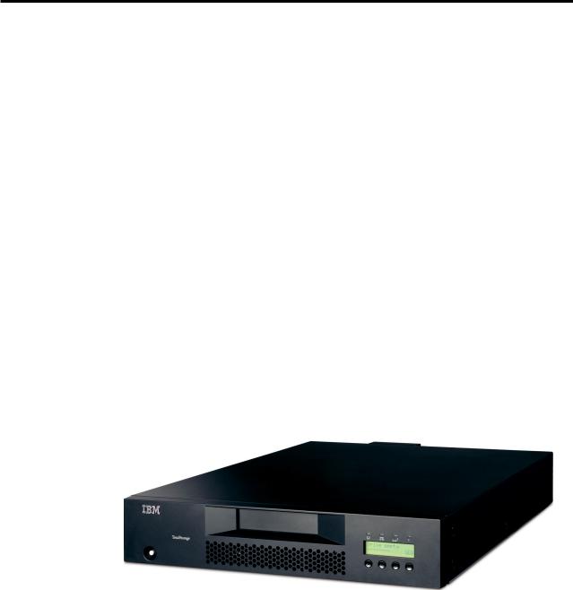
|
Product Description |
| |
The IBM TotalStorage® Ultrium Tape Autoloader 3581 Models L28/L38/L3H and |
| |
F28/F38/F3H offer high capacity, performance, and technology designed for the |
| |
mid-range open systems environment. These models incorporate a single Linear |
| |
Tape Open (LTO) IBM TotalStorage Ultrium 2 (Models L28/F28) or Ultrium 3 |
| |
(Models L38/F38/L3H/F3H) Tape Drive. The IBM TotalStorage Ultrium 3 Tape |
| |
Drive more than doubles tape drive performance over the previous generation |
| |
Ultrium 2 Tape Drive, with up to 80 MB per second native data transfer rate. In |
| |
addition, with the use of the new IBM TotalStorage Ultrium 400 GB Data |
| |
Cartridge, the Ultrium 3 Tape Drive has the capability of writing twice as much |
| |
data, up to 400 GB native capacity (800 GB with 2:1 compression). |
| |
The Model L28/L38/L3H comes with an LVD Ultra160 SCSI attachment, while the |
| |
Model F28/F38/F3H comes with a Native Switched Fabric Fibre Channel |
| |
attachment, for connection to a wide spectrum of open systems servers. Both |
| |
models connect to a wide spectrum of open systems servers. Note that the Ultrium |
| |
3 Tape Drive does not support HVD technology. |
| |
The 3581 Tape Autoloader is a desktop or rack-mountable unit (requiring two rack |
| |
units) that operates in automatic, sequential, or random mode and comes equipped |
| |
with a robotic interface that moves tape cartridges to and from the drive and |
| |
cartridge carousel. With an eight tape cartridge capacity, it provides a media |
| |
capacity of up to 3.2 TB (6.4 TB with 2:1 compression) data storage per unit. |
| |
Optional features include an HVD Converter, a Remote Management Unit (RMU), |
| |
and a Bar Code Reader (BCR). |
|
|
a67s0243 |
|
Figure 2. IBM TotalStorage Ultrium Tape Autoloader 3581 Models L28/L38/L3H and |
|
|
F28/F38/F3H |
|
| |
The Autoloader’s Ultrium 2 and Ultrium 3 Tape Drive offer: |
|
|
v |
Digital speed matching |
| |
|
The Ultrium 2 and Ultrium 3 Tape Drive will perform dynamic speed |
|
|
matching to adjust the drive’s native data rate as closely as possible to the |
|
|
net host data rate (after data compressibility has been factored out). This |
|
|
offers the dual benefit of reducing the number of backhitch repositions and |
|
|
improving throughput performance. |
|
v |
Power management |
© Copyright IBM Corp. 2004, 2005 |
3 |

The power management function controls the drive’s electronics to be either completely turned off or to be in a low-power mode. These power modes occur only when the circuit functions are not needed for drive operation.
v Channel calibration
The channel calibration feature allows for customization of each read/write data channel for optimum performance. The customization enables compensation for variations in the recording channel transfer function, media characteristics, and read/write head characteristics.
v Separate writing of multiple filemarks
Separate writing of multiple filemarks causes any write command of two or more filemarks to cause a separate data set to be written containing all filemarks after the first. This feature has two advantages:
-First, it can improve performance if a subsequent append overwrites somewhere after the first filemark.
-Second, write of multiple filemarks typically indicates a point where an append operation might occur after the first of these filemarks.
|
|
This change prevents having to rewrite datasets containing customer data |
|
|
and the first filemark in cases when (where) such an append occurs. |
|
v |
Large internal buffer |
| |
|
The Ultrium 2 Tape Drive and has a 64 MB internal data buffer. The Ultrium |
| |
|
3 Tape Drive has a 128 MB internal buffer . |
| |
v |
Fast cartridge fill times (for Ultrium 3, Ultrium 2 and Ultrium 1 data cartridges) |
|
v Fast data access, rewind, and load times |
|
| Table 1. Data access, rewind, and load times |
|
|
||
| |
|
|
|
|
Action |
Autoloader |
Ultrium 2 Tape Drive |
Ultrium 3 Tape Drive |
|
| |
|
|
|
|
Cartridge Load Time |
32 seconds |
15 seconds |
10 seconds |
|
| |
|
|
|
|
Maximum Rewind Time |
N/A |
80 seconds |
88 seconds |
|
| |
|
|
|
|
Average File Access Time |
N/A |
49 seconds |
49 seconds |
|
| |
|
|
|
|
|
|
|
|
|
Product Features
This section describes the standard and optional features of the Autoloader.
Standard Features
The Autoloader includes the following standard features: v Operator Control Panel (OCP)
The OCP provides an easy-to-read display and a four button keypad allowing the user to monitor and control the operations of the Autoloader. The OCP’s display provides access to library status, commands, setup, and tools. See “Front Panel Components” on page 7 and “Operator Control Panel (OCP)” on page 46 for additional information.
v Robotic system
The Autoloader’s robotic system includes an I/O Door, a cartridge carousel with cartridge slots, and a cartridge loader. The I/O Door allows importing or exporting a single cartridge to or from the Autoloader. The cartridge
| carousel encircles the Ultrium 2 and Ultrium 3 Tape Drive and positions the specified cartridge slot in front of the tape drive. A robotic cartridge loader moves the cartridges between the cartridge slots and the tape drive.
4 IBM 3581 Autoloader Models L28/L38/L3H and F28/F38/F3H Setup, Operator, and Service Guide
v Eight-cartridge capacity
| |
Up to eight Ultrium 3, Ultrium 2 or Ultrium 1 tape cartridges can be stored |
|
in cartridge slots mounted on the carousel. |
v |
Cartridge inventory |
|
Each time the Autoloader is powered on, an inventory of all cartridge slots is |
|
performed. |
Setup Guide: Product Description 5
|
v Built-in diagnostics |
|
The Autoloader includes firmware that performs diagnostic tests and reports |
|
drive operating status. An error and event log is available through the OCP |
|
or optional RMU. |
| |
v Ultrium 2 or Ultrium 3 Tape Drive |
| |
The Autoloader is available with an LVD SCSI (Model L28/L38/L3H) or a |
| |
Fibre Channel (Model F28/F38/F3H) Ultrium 2 or Ultrium 3 Tape Drive. |
Optional Features
The Autoloader has the following optional features: v Bar Code Reader (BCR)
The BCR reads bar code labels and sends the label IDs to the server (host) and to the Remote Management Unit (RMU), if installed.
v Remote Management Unit (RMU)
The RMU provides remote access to the Autoloader over a network via a web browser and makes functions accessible without the need for a dedicated server or separate software.
v HVD Converter
The HVD Converter is a SCSI HVD to LVD converter/expander. It converts the Autoloader’s low voltage differential (LVD) to wide high voltage differential (HVD). This allows LVD-peripherals to be used on an HVD bus. The converter can also be used to reshape poor quality LVD signals, and allow additional cable length.
v Rack Mount Kit
The Rack Mount Kit supplies the necessary mounting hardware to install the
Autoloader in a 19-inch rack.
6 IBM 3581 Autoloader Models L28/L38/L3H and F28/F38/F3H Setup, Operator, and Service Guide
Loading...