


LV-671
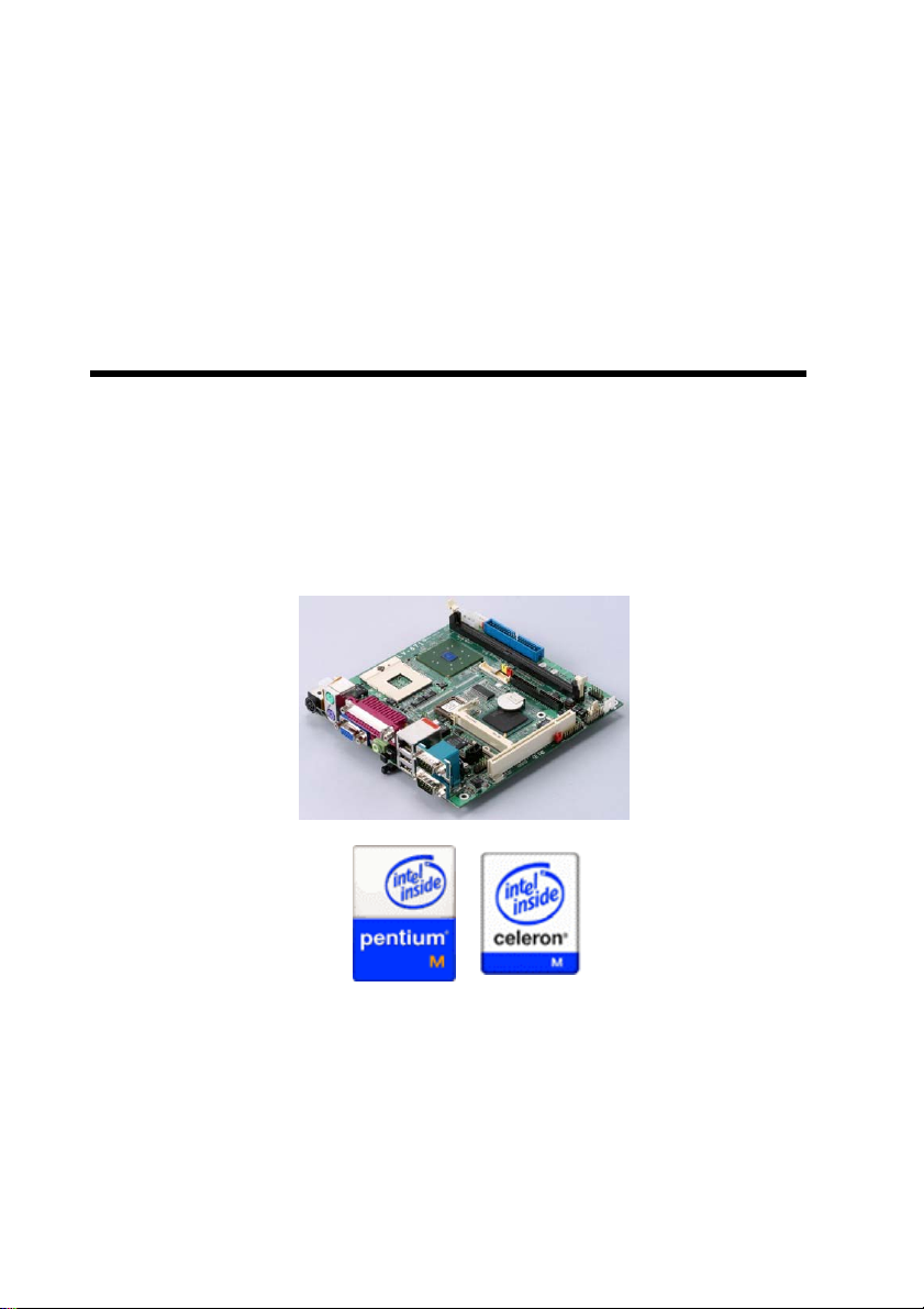
LV-671
Mini-ITX Motherboard
User’s Manual
Edition: 1.42
2007/11/19
LV-671 User’s Manual
2
LV-671 User’s Manual
3

LV-671 User’s Manual
Copyright
Copyright© 2003 - 2004. All rights reserved. This document is copyrighted and all rights are
reserved. The information in this document is subject to change without prior notice to
make improvements to the products.
This document contains proprietary information and protect ed by copyright. No part of this
document may be reproduced, copied, or translated in any form or any means without prior
written permission of the manufacturer.
All trademarks and/or registered trademarks contains in this document are property of their
respective owners.
Disclaimer
The company shall not be liable for any incidental or consequential damages resulting from
the performance or use of this product.
The company does not issue a warranty of any kind, express or implied, including without
limitation implied warranties of merchantability or fitness for a particular purpose.
The company has the right to revise the manual or include changes in the specifications of
the product described within it at any time without notice and without obligation to notify any
person of such revision or changes.
Trademark
All trademarks are the property of their respective holders.
Any questions please visit our website at http://www.commell.com.tw.
4
LV-671 User’s Manual
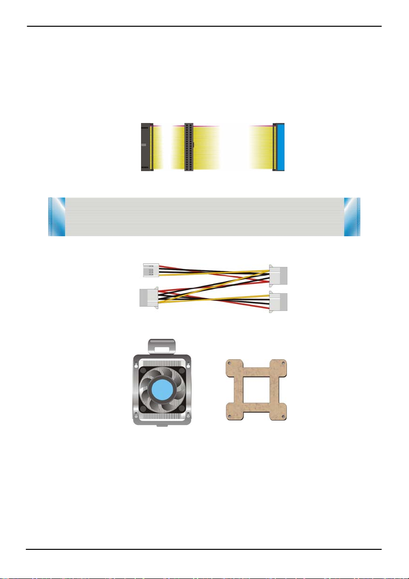
Packing List
Please check the package before you use this product
Hardware:
LV-671 Mini-ITX motherboard x 1
Cable Kit:
40-pin ATA100 IDE Cable x 1
26-pin Slim Type Floppy Cable x 1
4-pin to 4-pin Power Cable x 1
Other Accessories
Driver CD (Including User’s Manual ) x 1
CPU Cooler x 1
5

LV-671 User’s Manual Index
Index
Chapter 1 <Introduction>.....................................................................................9
1.1 <Product Overview>..........................................................................9
1.2 <Product Specification>.........................................................................10
1.3 <Component Placement> ......................................................................13
1.4 <Block Diagram>....................................................................................14
Chapter 2 <Hardware Setup>.............................................................................15
2.1 <Connector Location>............................................................................15
2.2 <Jumper Reference> .............................................................................16
2.3 <Connector Reference>.........................................................................17
2.3.1 <Internal Connector>..................................................................17
2.3.2 <External I/O connector> ...........................................................17
2.4 <System Setup>.....................................................................................18
2.4.1 <CPU Installation>......................................................................18
2.4.2 <Memory Installation>................................................................19
2.4.3 <CPU Cooler Installation>..........................................................20
2.5 <CMOS Setup>......................................................................................21
2.6 <IDE Interface>......................................................................................22
2.7 Compact Flash Interface........................................................................23
2.8 <Display Interface> ................................................................................24
2.8.1 <Analog display interface>.........................................................24
2.8.2 <Digital display interface> ..........................................................24
2.9 <Audio Interface>...................................................................................28
2.10 <Ethernet Interface> ............................................................................30
2.11 <Power and Fan connector>................................................................31
2.12 <GPIO Interface>.................................................................................33
2.13 <Expansive Interface> .........................................................................34
2.14 <Switch and Indicator>.........................................................................35
6

LV-671 User’s Manual Index
Chapter 3 <System Setup> ................................................................................37
3.1 <Watchdog Timer Setting>.....................................................................37
3.2 <Audio Setting>......................................................................................38
3.3 <Display Device Setup>.........................................................................39
Chapter 4 <BIOS Setup> .................................................................................... 43
Appendix A <I/O Port Pin Assignment>............................................................45
A.1 <IDE Port>.............................................................................................45
A.2 <Floppy Port> ........................................................................................47
A.3 < USB Interface > ..................................................................................47
A.4 <IrDA Port>............................................................................................48
A.5 < VGA Port >..........................................................................................48
A.6 < LAN Port >..........................................................................................48
A.7 < Serial Port >........................................................................................49
Appendix B <Flash BIOS>..................................................................................51
B.1 <Flash Tool> ..........................................................................................51
B.2 <Flash BIOS Procedure>.......................................................................51
Appendix C <System Resource> ......................................................................53
C.1 <I/O Address Map>................................................................................53
C.2 <Memory Address Map>.......................................................................55
C.3 <System IRQ and DMA Resource>.......................................................56
Contact Information............................................................................................58
7

LV-671 User’s Manual
(This Page is Left for Blank)
8

LV-671 User’s Manual Introduction
Chapter 1 <Introduction>
1.1 <Product Overview>
LV-671 is an all-in-one industrial compact Pentium-M level motherboard based on Mini-ITX
form factor at 170 x 170 mm of dimension. Based on Intel 855GME and ICH4 chipset,
LV-671 offers the compact, embedded, value and high performance solution with Intel
Pentium-M CPU, 400MHz/533MHz of FSB, 1GBytes DDR200/266/333 SDRAM with ECC,
Intel 855GME GMCH built-in Intel Extreme Graphics 2, Intel PRO/1000+ LAN, Hi-Spee d
USB 2.0, 5.1 channel and S/P DIF 3D audio, 18/24-bit dual channe l LVDS, GPIO and
embedded flash disk interfaces.
Low Power Consumption Solution
Based on Intel 855GME chipset and Intel Pentium M/Celeron M processor, the bo ard
requires lower power consumption than Pentium 4 –M processors. The Intel Pentium M
integrates 512KB/1MB/2MB of L2 cache, so it provides better performance than before.
Dual Display Architecture
Intel 855GME supports two DAC for display interface; users can apply two display
devices for dual display clone or extended desktop display. With this feature, system
integrator can use this board for Kiosk, ATM, or industrial control machines.
5.1 Channel AC97 Audio
LV-671 integrates a REALTEK 5.1 channel AC97 codec; users can enjoy the live
surround sound through 5.1 channel speakers. LV-671 also has an S/PDIF jack for digital
sound outputting.
Hi-Speed USB 2.0 Interface
Intel ICH4 built-in Hi-Speed USB 2.0 controller let LV-671 offer up to 480Mbps of
transferring rate.
Card Bus and Embedded Flash Disk
The LV-671 support PCMCIA Type I/II enable you can simply use the wireless LAN
module or other extended devices, the Compact Flash interface and IDE1 with DOM
support can let you port any embedded system onboard.
Mini-PCI and Mini-AGP interface
With Mini-PCI interface, users can add a wireless LAN module or video capture
module for powerful communication solutions. With Mini-AGP interface, users can apply
the AGP graphic card or additional video output module such as HDTV or DVI.
Product Overview 9

LV-671 User’s Manual
1.2 <Product Specification>
General Specification
Form Factor Mini-ITX motherboard at 170 x 170 mm (L x W)
CPU Package: 478 pin PGA/ 479 pin BGA
L2 Cache: 512KB/1MB/2MB
FSB: 400MHz/533MHz
( The Intel® Celeron® M Processor 4xx series have been
designed to work with the Mobile Intel® 945 Express Chipset
Family only .)
Memory 1GBytes DDR200/266/333 SDRAM on one 184-pin DIMM socket
ECC memory is supported
Chipset Intel 82855GME GMCH and 82801DB ICH4
BIOS Phoenix-Award v6.00PG 4Mb PnP flash BIOS
Green Function Power saving mode includes doze, standby and suspend modes.
ACPI version 1.0 and APM version 1.2 compliant
Watchdog Timer System reset programmable watchdog timer with 1 ~ 255
sec./min. of timeout value
Real Time Clock Intel ICH4 built-in RTC with lithium battery
Enhanced IDE PCI enhanced IDE interface supports dual channels and up to 4
ATAPI devices at UltraATA/100
One 40-pin and one 44-pin IDE port
DiskOnModule (DOM) embedded flash disk up to 6GBytes
Multi-I/O Port
Chipset Intel 82801DB ICH4 (USB) and Winbond W83627HF-AW LPC
Super I/O controller
Serial Port Two external RS-232 serial port with 16C550 compatible UART
and 16 bytes FIFO
USB Port Six Hi-Speed USB 2.0 ports with 480 Mbps of transfer rate
Two external and four internal USB ports
Parallel Port One external bi-direction parallel port with SPP/ECP/EPP mode
Floppy Port One slim-type FDD port supports up to two FDD
IrDA Port One IrDA compliant Infrared interface supports SIR
K/B & Mouse External PS/2 keyboard and mouse ports on rear I/O panel
GPIO One 20-pin Digital I/O connector with 15-bit programmable I/O
interface
Card Bus
PCMCIA One PCMCIA Type I/II slot
VGA Display Interface
Chipset Intel 855GME GMCH built-in Intel Extreme Graphics 2
With 266 MHz VGA core and 256-bit 3D engine
10

LV-671 User’s Manual Introduction
Frame Buffer Intel DVMT (Dynamic Video Memory Technology) 2.0 up to
64Mbytes shared with system*
Display Type CRT and LCD monitors for analog display
24-bit single/dual channel LCD panel for digital display
Connector External DB15 female connector on rear I/O panel
Internal 40-pin LVDS connector
*Under Windows 98/ME/2000/XP/Server2003 or Linux kernel 2.4 later
Ethernet Interface
Chipset Intel PRO/1000+ LAN interface with Intel 82540EM
Type 10Base-T / 100Base-TX/1000Base-T,
auto-switching Fast Ethernet
Full duplex, IEEE802.3U compliant
Connector External RJ45 connector with LED on rear I/O panel
Audio Interface
Chipset Intel ICH4 with REALTEK ALC655 AC97 3D audio codec
Interface 5.1 channel 3D audio with front (R/L), rear (R/L), center and bass
Optical Fiber digital audio encoding signal output
Connector Optional external three phone jack for 5.1 channel audio onboard
External Amplified Speaker output jack on rear panel
External SPDIF connector on rear panel
Internal 10-pin header for line-in/-out, MIC-out, 4-pin header for
CD-in
Solid State Disk Interface
Flash Type Compact Flash Type-I for Compact Flash Card or IBM Micro Drive
Capacity Up to 1GB flash memory
Expansion Interface
Slim PCI Slot One slim type PCI slot supports up to 2 bus master PCI
32-bit, 33MHz
Mini-PCI One Mini-PCI type B socket with 32-bit, 33MHz for LV-671MP
series
Mini-AGP One Mini-AGP socket with 4x AGP bus for LV-671MA series
Product Specification 11

LV-671 User’s Manual
Power and Environment
Power
Requirement
One external 19V/12V (auto switching) DC Adapter connector on
rear panel
4-pin onboard 12V P4 4-pin power connector
(Two power resources selectable for each)
Input Voltage
Range
11V ~ 13V for 12V power supply
16V ~ 20V for 19V power supply
Input Current 12V/60W (with one 5.25” CDROM and 3.5” HDD)
19V/60W (with one 5.25” CDROM and 3.5” HDD)
Dimension 170 (L) x 170 (H) mm, Mini-ITX form factor
Temperature Operating within 0 ~ 60oC (32 ~ 140oF)
Storage within -20 ~ 85
o
C (-4 ~ 185oF)
Ordering Code
LV-671-MA Mini-ITX Socket 479 Pentium-M processor Motherboard
with Intel Extreme VGA, LAN, 5.1-CH/SPDIF Audio,
Hi-Speed USB 2.0, mini-AGP socket and LVDS interface.
LV-671-MP Mini-ITX Socket 479 Pentium-M processor Motherboard
with Intel Extreme VGA, LAN, 5.1-CH/SPDIF Audio,
Hi-Speed USB 2.0, mini-PCI socket and LVDS interface.
LV-671-MAPM11 Same as LV-671-MA and with onboard Intel Pentium M 1.1GHz
processor for ULV/LV version.
LV-671-MPPM11 Same as LV-671-MP and with onboard Intel Pentium M 1.1GHz
processor for ULV/LV version.
LV-671-MACM6 Same as LV-671-MA and with onboard Intel Celeron M 600MHz
processor for ULV/LV version.
LV-671-MPCM6 Same as LV-671-MP and with onboard Intel Celeron M 600MHz
processor for ULV/LV version.
For further product information please visit the website at http://www.commell.com.tw
Product Specification 12
LV-671 User’s Manual Introduction
A
A
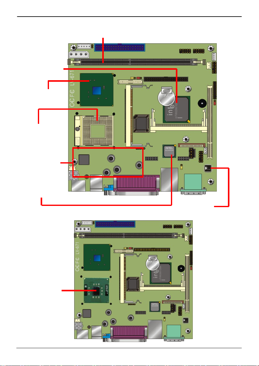
1.3 <Component Placement>
Intel ICH4
(Southbridge)
Intel 855GME
(Northbridge)
Socket479
For 478-pin PGA
Pentium M/Celeron M
Onboard DC
to DC inverter
Intel 82540EM
1 x 184-pin DDR266/333 DIMM up to 1GB
Gigabit LAN
Onboard
479-pin BGA
Pentium M/Celeron M
REALTEK
LC655 5.1CH
udio Codec
For embedded
CPU version
Component Placement 13
LV-671 User’s Manual
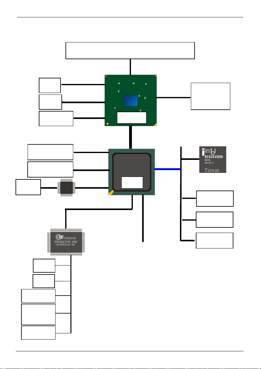
1.4 <Block Diagram>
Intel Pentium M processor with FC-PGA2/FC-BGA2
400MHz/533MHz FSB
ATAPI Devices
USB Devices
Audio
IrDA
CRT
LCD
Mini-AGP
AC97 Codec
LVDS
LVDS
AGP 4x
DVO B/C
UltraATA100
USB2.0
480Mb/s
LPC
855GME
ICH4
Compact Flash
DDR266/333
PCI Bus
33MHz
1 x 184-pin
DIMM
Up to 1GB
Gigabit Ethernet
Controller
Slim PCI
Mini-PCI
PCMCIA
PS/2
COM Port
Parallel
Port
Floppy
Block Diagram 14
LV-671 User’s Manual Hardware Setup
R
V
Chapter 2 <Hardware Setup>
This chapter contains the information for installation of hardware. The install procedure
includes jumper settings, CPU and memory installation, fan, I/O and panel connections.
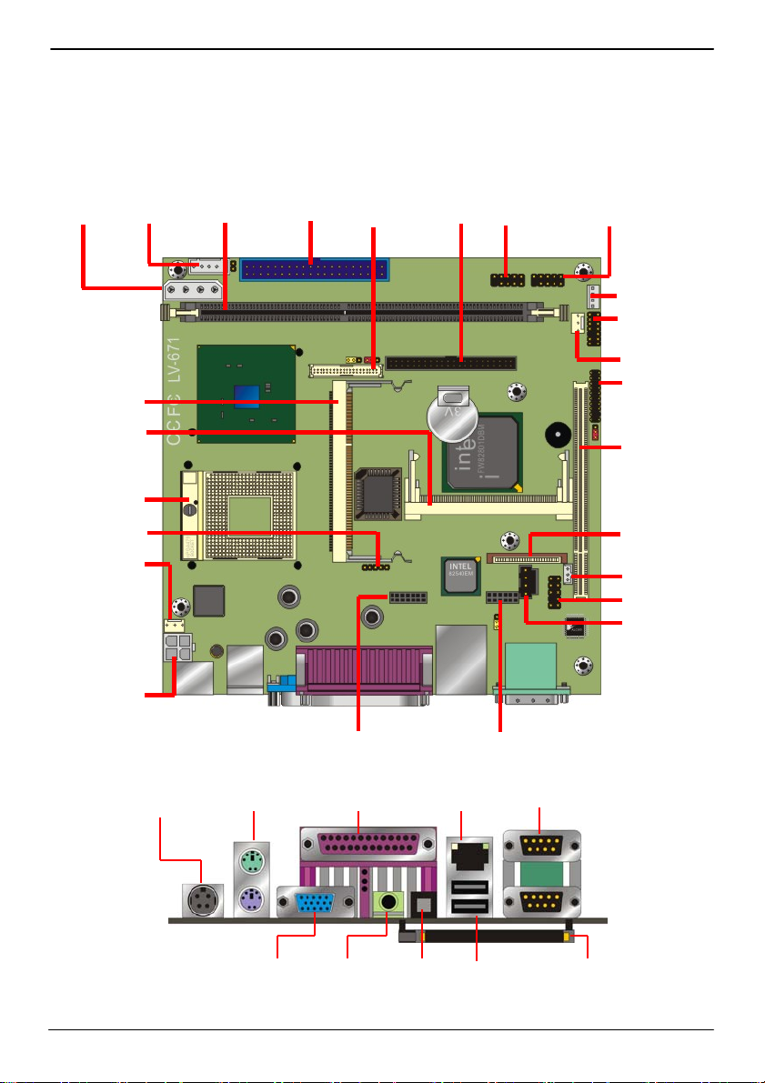
2.1 <Connector Location>
CN_BPWR CN_INV DIMM IDE1 CN_LVDS IDE2 CN_USB1 CN_USB2
CN_SPWR
JFRNT
SYSFAN
CN_DIO
MINI_AGP
MINIPCI
CPU
CN_I
CPUFAN
PCI
FDD
CN_WOL
CN_AUDIO
CDIN
CN 12
CN_2ND_IO CN_LAN2
DC_IN PS/2 Printer LAN COM2/1
VGA SPEAKER SP/DIF Dual_USB PCMCIA
Connector Location 15
LV-671 User’s Manual Hardware Setup
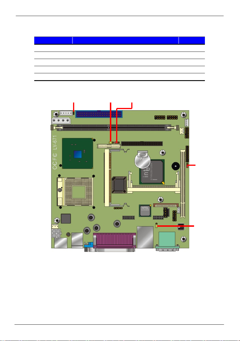
2.2 <Jumper Reference>
Jumper Function
JRTC COMS Operate / Clear Setting
JLAN LAN1 Enable/Disable
JVLCD LCD Panel Voltage Setting
JCFSEL Compact Flash Address Setting
JDOM IDE1 5V Voltage Enable/Disable
JCFSEL JVLCD JDOM
JRTC
JLAN
Jumper Reference 16

LV-671 User’s Manual Hardware Setup
2.3 <Connector Reference>
2.3.1 <Internal Connector>
Connector Function Remark
CPU MicroPGA479 CPU Socket Standard
DIMM 184-pin DIMM Socket Standard
IDE1 40-pin Primary IDE Port Standard
IDE2 44-pin Secondary IDE Port Standard
FDD 26-pin slim type FDD Port Standard
CN_USB1 10-pin 3rd / 4th Hi-Speed USB 2.0 Port Standard
CN_USB2 10-pin 5th / 6th Hi-Speed USB 2.0 Port Standard
CN_IR 5-pin SIR IrDA Port Standard
CN_12V 4-pin AT Power Connector Standard
CN_BPWR 4-pin 5V&12V output connector Standard
CN_SPWR 4-pin 5V&12V output connector Standard
JFRNT 14-pin Switch and Indicator Connector Standard
CPUFAN 3-pin +12V CPU Fan Connector Standard
SYSFAN 3-pin +12V System Fan Connector Standard
CN_AUDIO 10-pin Audio Port Standard
CDIN 4-pin CD-in Interface Standard
CN_WOL 3-pin Wake-On-LAN Interface Standard
CN_LVDS 40-pin LVDS connector Standard
CN_INV 5-pin LCD Inverter Power Connector Standard
CN_DIO 20-pin programmable I/O connector Standard
CN_LAN2 Additional Ethernet Controller Interface Standard
CN_2ND_IO Additional I/O module interface Standard
CF Compact Flash Card Interface Standard
PCMCIA PCMCIA Card bus interface Standard
2.3.2 <External I/O connector>
Connector Function Remark
DC_IN 4-pin 12V/19V auto-switching input Standard
PS2 PS/2 type keyboard and mouse port Standard
Printer DB26 parallel port Standard
VGA DB15 VGA port Standard
SPEAKER Amplified speaker out Standard
SPDIF Digital audio output Standard
LAN RJ45 LAN port Standard
DUAL_USB USB connectors Standard
COM1/2 RS232 DB9 serial port Standard
PCMCIA Car bus slot Standard
Connector Reference 17
LV-671 User’s Manual Hardware Setup
W
A
y
2.4 <System Setup>
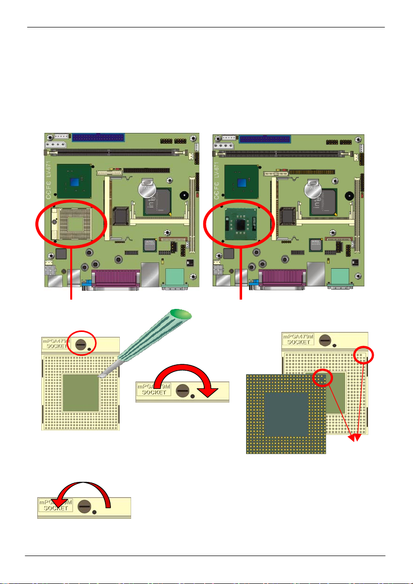
2.4.1 <CPU Installation>
The board supports Intel Pentium M/ Celeron M processor with 400MHz/533MHz of front
side bus, 512KB/1MB/2MB of L2 cache, there are two package type of the processor,
478-pin PGA for socket479 onboard version; 479-pin BGA for embedded processor version.
Please check installation steps below for onboard socket479 version.
Socket479 for Intel Pentium M/Celeron M
ith 478-pin PG
Unlock wa
1. Use the flat-type
screw drive to unlock
the CPU socket
3. Lock the socket
Embedded Intel Pentium M/Celeron M
With 479-pin LV/ULV
Check point
2. Follow the pin direction to install
the processor on the socket
CPU Installation 18
 Loading...