


|
MaxLoader User’s Guide |
1. INTRODUCTION.................................................................................................................................... |
7 |
PROGRAMMER MODELS FOR PC USB INTERFACE ....................................................................................... |
7 |
PROGRAMMER MODELS FOR PC USB INTERFACE MULTI-SOCKETS............................................................ |
8 |
PROGRAMMER MODELS FOR PC PARALLEL INTERFACE............................................................................... |
8 |
ABOUT THIS MANUAL ................................................................................................................................. |
9 |
GENERAL DESCRIPTION ............................................................................................................................... |
9 |
2. GETTING STARTED / INSTALLATION ......................................................................................... |
10 |
INSTALLATION REQUIREMENTS ................................................................................................................. |
10 |
HARDWARE INSTALLATION ....................................................................................................................... |
10 |
To Install the software from a CD drive.............................................................................................. |
10 |
TO START THE WINDOWS SOFTWARE ......................................................................................................... |
10 |
TO INSTALL SOFTWARE AND CONNECT TO PC FOR USB PROGRAMMERS ................................................... |
10 |
TO INSTALL THE SOFTWARE FOR PARALLEL PORT PROGRAMMERS ............................................................ |
17 |
To download the software from the www.eetools.com web site .......................................................... |
17 |
SELECT PRODUCT ...................................................................................................................................... |
18 |
3. FAMILIES OF PROGRAMMABLE DEVICES ................................................................................ |
19 |
NVM: NON VOLATILE MEMORY............................................................................................................ |
19 |
ROM: READ ONLY MEMORY ................................................................................................................. |
19 |
OTP: ONE TIME PROGRAMMABLE ROM................................................................................................ |
19 |
EPROM: ERASABLE PROGRAMMABLE ROM......................................................................................... |
19 |
EEPROM: ELECTRICALLY ERASABLE & PROGRAMMABLE ROM.......................................................... |
19 |
NVM HIERARCHY ..................................................................................................................................... |
19 |
SERIAL FLASH EEPROM........................................................................................................................... |
21 |
SERIAL EEPROM...................................................................................................................................... |
21 |
NON-TYPICAL DEVICES............................................................................................................................. |
22 |
8-BIT 1-MEGABITS..................................................................................................................................... |
22 |
16-bit 1-Megabits.................................................................................................................................. |
23 |
ERASING AN EPROM ................................................................................................................................ |
23 |
PLD........................................................................................................................................................... |
23 |
|
1 |

MaxLoader User’s Guide
PLD Features ....................................................................................................................................... |
24 |
||||
MICROCONTROLLER .................................................................................................................................. |
25 |
||||
ABOUT “DEVICE ID” AND “AUTO SELECT” ON EE TOOLS PROGRAMMERS ............................................... |
26 |
||||
4. TERMS AND SYMBOLS USED IN THE GUIDE............................................................................. |
28 |
||||
SAFETY NOTE CONVENTIONS .................................................................................................................... |
28 |
||||
OTHER TERMS AND DEFINITIONS ARE AS FOLLOWS.................................................................................... |
28 |
||||
CHOOSING A RIGHT ADAPTER ................................................................................................................... |
29 |
||||
Different Device Packages.................................................................................................................... |
30 |
||||
Different Programming Adapters ......................................................................................................... |
31 |
||||
5. QUICK START EXAMPLES............................................................................................................... |
32 |
||||
PROGRAMMING AN EPROM WITH DATA ................................................................................................... |
32 |
||||
DUPLICATING AN EPROM FROM A MASTER IC DEVICE............................................................................. |
34 |
||||
6. MAXLOADER OPERATIONS............................................................................................................ |
35 |
||||
BASIC MENU SCREEN INFORMATION......................................................................................................... |
35 |
||||
Option Information.............................................................................................................................. |
35 |
||||
(Additional Option Information for Non PLD Devices) ..................................................................... |
36 |
||||
System Information.............................................................................................................................. |
36 |
||||
Counter................................................................................................................................................. |
36 |
||||
File........................................................................................................................................................ |
37 |
||||
|
Binary Format................................................................................................................................ |
38 |
|||
|
Intel HEX Format .......................................................................................................................... |
38 |
|||
|
Motorola S HEX Format........................................................................................................... |
39 |
|||
|
TEKTRONIX HEX FORMAT......................................................................................................... |
40 |
|||
|
ASCII HEX format .................................................................................................................. |
40 |
|||
|
JEDEC Standard <PLD devices only> ............................................................................................. |
41 |
|||
|
POF file <Altera EPMxxx devices only> ........................................................................................ |
43 |
|||
|
File / Load |
......................................................................................................................................... |
|
43 |
|
|
File / Reload |
..................................................................................................................................... |
44 |
||
|
File / Save |
......................................................................................................................................... |
45 |
||
|
|
|
|
|
|
2 |
|
|
|
|
|

|
MaxLoader User’s Guide |
File/ Load Project ............................................................................................................................. |
45 |
File/ Save Project.............................................................................................................................. |
45 |
File/ Save Log................................................................................................................................... |
46 |
File/ Save All Messages ................................................................................................................... |
47 |
Buffer ................................................................................................................................................... |
48 |
Buffer / Edit Buffer........................................................................................................................... |
49 |
Find................................................................................................................................................... |
49 |
Find Next .......................................................................................................................................... |
50 |
Fill Buffer ......................................................................................................................................... |
50 |
Fill random data................................................................................................................................ |
50 |
Copy buffer....................................................................................................................................... |
51 |
Fill Buffer ......................................................................................................................................... |
51 |
Clear buffer...................................................................................................................................... |
52 |
Print buffer........................................................................................................................................ |
53 |
Set editor to view mode .................................................................................................................... |
53 |
Set editor to edit mode...................................................................................................................... |
54 |
Set Editor to binary mode ................................................................................................................. |
54 |
Set editor to 8 bit(byte) Hex ............................................................................................................. |
55 |
Set editor to 16 bit(word) Hex .......................................................................................................... |
55 |
Set editor to 32 bit(double word) Hex .............................................................................................. |
56 |
Set default editor mode ..................................................................................................................... |
56 |
Set default Reset Editor .................................................................................................................... |
57 |
Swap nibble ...................................................................................................................................... |
57 |
Swap byte ......................................................................................................................................... |
58 |
Swap Word ....................................................................................................................................... |
58 |
Swap double word ............................................................................................................................ |
59 |
Jedec editor ....................................................................................................................................... |
59 |
Clear ................................................................................................................................................. |
60 |
Close ................................................................................................................................................. |
61 |
Buffer / Edit UES ............................................................................................................................. |
61 |
Device ................................................................................................................................................... |
61 |
|
3 |

MaxLoader User’s Guide
|
Device / Select by history |
................................................................................................................. |
|
|
62 |
|||||||||||||
|
Select |
................................................................................................................................................ |
|
|
|
|
|
|
|
|
|
|
|
|
|
|
|
63 |
|
Select / E (E)PROM, FLASH ........................................................................................................... |
64 |
||||||||||||||||
|
Select / PLD ...................................................................................................................................... |
|
|
|
|
|
|
|
|
|
|
64 |
||||||
|
Select / Microcontroller .................................................................................................................... |
64 |
||||||||||||||||
|
Select / PROM .................................................................................................................................. |
|
|
|
|
|
|
|
|
|
|
64 |
||||||
|
Select / Auto Select |
........................................................................................................................... |
|
|
|
|
|
|
64 |
|||||||||
|
Select / Device information |
|
|
65 |
||||||||||||||
|
Device / Change Algorithm |
|
|
66 |
||||||||||||||
|
Device / Auto Menu Option |
............................................................................................................. |
|
67 |
||||||||||||||
|
Device / Blank Check |
....................................................................................................................... |
|
|
67 |
|||||||||||||
|
Device / Program |
.............................................................................................................................. |
|
|
|
|
|
|
|
|
|
69 |
||||||
|
Device / Read |
................................................................................................................................... |
|
|
|
|
|
|
|
|
|
|
|
|
72 |
|||
|
Device / Verify |
................................................................................................................................. |
|
|
|
|
|
|
|
|
|
|
|
72 |
||||
|
Device / Data Compare |
..................................................................................................................... |
|
73 |
||||||||||||||
|
Device / Erase |
................................................................................................................................... |
|
|
|
|
|
|
|
|
|
|
|
|
73 |
|||
|
Device / Security |
.............................................................................................................................. |
|
|
|
|
|
|
|
|
|
73 |
||||||
|
Device / Encryption |
.......................................................................................................................... |
|
|
74 |
|||||||||||||
|
Device / Option |
................................................................................................................................. |
|
|
|
|
|
|
|
|
|
|
|
74 |
||||
|
Device / Auto |
.................................................................................................................................... |
|
|
|
|
|
|
|
|
|
|
|
75 |
||||
Test (This feature is for only TopMax, TopMaxII)................................................................................ |
75 |
|||||||||||||||||
|
Test / RAM Test |
............................................................................................................................... |
|
|
|
|
|
|
|
|
|
|
75 |
|||||
|
Test / Vector Test |
|
............................................................................................................................. |
|
|
76 |
||||||||||||
|
Test / IC Test |
.................................................................................................................................... |
|
|
|
|
|
|
|
|
|
|
|
77 |
||||
|
Config |
|
|
|
|
78 |
||||||||||||
|
|
Config / Select Product |
||||||||||||||||
|
|
79 |
||||||||||||||||
Config / Config Option |
||||||||||||||||||
|
Config Option / Buffer Clear Before File Loading................................................................. |
79 |
||||||||||||||||
|
Config Option / Blank Check Before Programming............................................................... |
80 |
||||||||||||||||
|
Config Option / Verify After Reading...................................................................................... |
80 |
||||||||||||||||
|
Config Option / verify after programming .............................................................................. |
80 |
||||||||||||||||
|
Config Option / Byte order swapping ...................................................................................... |
80 |
||||||||||||||||
4

MaxLoader User’s Guide |
|
Config Option / Device Insert Test .......................................................................................... |
82 |
Config Option / Device ID Check ............................................................................................ |
82 |
Config Option / Sound ............................................................................................................. |
83 |
Config Option / Default Buffer Value..................................................................................... |
83 |
Config Option / 32 Bit Checksum............................................................................................ |
83 |
Config Option / Port (TopMax, ChipMax) ....................................................................................... |
84 |
Config Option / USB Option (USB programmer) ............................................................................ |
85 |
USB option / Enable START button........................................................................................ |
85 |
If you want to choose the master socket in 4th location in 8 sockets, select the serial number for |
|
4th socket among 8 sequential serial numbers. i.e the 4th socket serial number is P8-0057...... |
86 |
USB option / Good LED off on socket open............................................................................ |
86 |
USB option / Enable “START ALL” button ........................................................................... |
86 |
Config Option / Gang Split Select .................................................................................................... |
87 |
Split........................................................................................................................................... |
88 |
Device Address ......................................................................................................................... |
90 |
File Load .................................................................................................................................. |
90 |
File Save ................................................................................................................................... |
91 |
Config Option / Auto Inc .................................................................................................................. |
91 |
Config / Hardware test...................................................................................................................... |
92 |
Config / Concurrent (gang) mode ..................................................................................................... |
92 |
How to program (write) one file into different sockets ? ........................................................ |
96 |
How to program (write) buffer ( blocks) data into different sockets ? ................................ |
99 |
Config / Enter Production Mode..................................................................................................... |
102 |
Config / Set Password..................................................................................................................... |
103 |
Config / Language .......................................................................................................................... |
103 |
7. TROUBLE SHOOTING & TECHNICAL SUPPORT .................................................................... |
104 |
1. REGISTRATION..................................................................................................................................... |
104 |
2. SOFTWARE UPDATES ........................................................................................................................... |
104 |
3. TESTING THE HARDWARE .................................................................................................................... |
104 |
4. QUICK SELF-DIAGNOSTICS .................................................................................................................. |
105 |
|
5 |

MaxLoader User’s Guide |
|
5. CONTACTING CUSTOMER SUPPORT...................................................................................................... |
106 |
6. SERVICE INFORMATION........................................................................................................................ |
107 |
7. LIMITED ONE-YEAR WARRANTY......................................................................................................... |
108 |
8. USEFUL WEB SITE ADDRESSES/ PHONE NUMBERS .............................................................................. |
109 |
9. PROGRAMMING ADAPTER MANUFACTURERS ...................................................................................... |
110 |
10. EPROM EMULATOR MANUFACTURERS ............................................................................................ |
110 |
8. OTHER PRODUCTS .......................................................................................................................... |
110 |
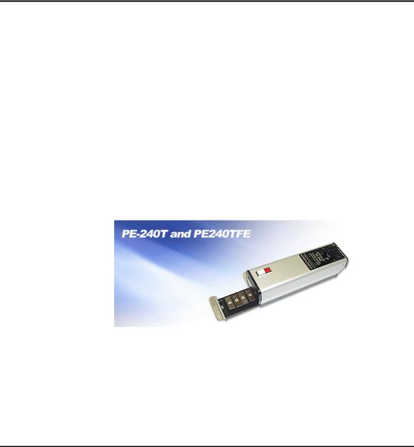
Optional EPROM Emulator ............................................................................................................ |
110 |
9. ABOUT NAND FLASH MEMORY................................................................................................... |
111 |
COMPARISON OF NOR AND NAND FLASH TECHNOLOGIES..................................................................... |
111 |
WHY NAND FLASH ................................................................................................................................ |
112 |
HOW TO PROGRAM NAND FLASH........................................................................................................... |
112 |
HOW TO READ NAND FLASH ................................................................................................................ |
113 |
10. GLOSSARY ....................................................................................................................................... |
113 |
6
MaxLoader User’s Guide
1. INTRODUCTION
This manual describes the operation of EE Tools’ programmers. TopMax/ChipMax/ChipMax2/TopMaxII/UniMax/ProMax8G (4G) are software, MaxLoader, driven device programmers. The information contained in this manual has been reviewed for accuracy, clarity, and completeness.
Please report in writing any errors or suggestions to support@eetools.com
EE Tools, Inc.
4620 Fortran Drive Suite 102
San Jose, CA 95134, USA. www.eetools.com
Tel : (408)263-2221 Fax : (408)263-2230
EE Tools reserves the right to use and distribute any information supplied without obligation.
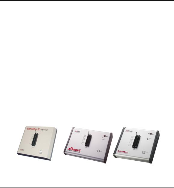
Programmer Models for PC USB Interface
7
MaxLoader User’s Guide
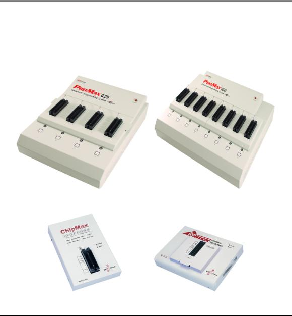
Programmer Models for PC USB Interface Multi-Sockets
Programmer Models for PC parallel Interface
8

MaxLoader User’s Guide
About This Manual
TopMax/ChipMax/ChipMax2/TopMaxII/UniMax/ProMax-8G (4G) User Guide explains how to install and run the programming software in your computer.
Chapter 2 contains instructions for installing and running MaxLoader.
Chapter 3 describes the most popular programmable devices.
Chapter 4 contains all terms and symbols used in the manual.
Chapter 5 describes basic operating examples of programmers.
Chapter 6 is organized by main operating commands and gives detailed instructions on each command.
Chapter 7 provides troubleshooting information for identifying and solving problems with programmers. It provides a detailed guide for EE Tools’ technical support and return material procedures.
Chapter 8 introduces a useful product, EPROM Emulator.
Chapter 9 describes the recent information of NAND Flash
Chapter 10 contains glossary about programmable devices and package types.
This Manual assumes that you have a working knowledge of your personal computer and its operating conventions.
General Description
TopMax/ChipMax/ChipMax2/TopMaxII/UniMax/ProMax-8G /4G are software driven device programmers that support a wide variety of programmable devices including: EPROM, EEPROM, Serial PROM, EPLD, PEEL, GAL, FPGA, and single chip Microcontroller.
TopMax/ChipMax easily connects to the parallel printer port of any IBM PC, and can operate with a full spectrum of IBM compatibles: PC 386, 486, Pentium, PS/2, portable (laptop), and clone computers. TopMaxII/UniMax/ProMax-8G (4G) connects to the USB(2.0) port of any IBM PC, and can operate with a full spectrum of IBM compatibles.
9

MaxLoader User’s Guide
The great advantage of a programmer is their programming speed and superior software. All programmers are controlled via a host IBM PC computer. The operating software has a user-friendly interface that includes window pulldown menus and virtual memory management to deal with very large files.
2. GETTING STARTED / INSTALLATION
Installation Requirements
MaxLoader is designed to operate with any 386, 486, Pentium, PS/2, Portable (notebook), compatibles running WIN 95/98/ ME/NT/2000/XP and Vista. The computer requires a CD-ROM drive, but a hard disk drive is also recommended.
Hardware Installation
The following section details the procedure for accomplishing the hardware installation procedure. TopMax / ChipMax easily connect to any parallel printer port in your computer and TopMaxII / ChipMax2/ UniMax / ProMax-8G (4G) connects to USB 2.0 port in your PC.
To Install the software from a CD drive
Place CD-ROM in the CD-ROM or DVD drive.
Choose a programmer model from the list of files located on the menu screen. The SETUP program will then launch the installation procedure.
To Start the windows software
To run the windows software, select your product model shortcut in the Windows Start Menu / Programs list.
From Configuration Menu, you can choose one of the TopMax/ChipMax/ChipMax2/TopMaxII/UniMax/ProMax-8G (4G) that you use.
To install software and connect to PC for USB programmers
The software works with Windows OS 98, SE, Me, 2000, XP and Vista.
10
MaxLoader User’s Guide
Follow the steps below for Windows.
1.Make sure a programmer is not connected when turning on your computer.
2.Note: If you see New Hardware Wizard screen then disconnect your programmer. You cannot install programmer software that way.
3.Insert the CD-ROM from factory (EE Tools) in your CD-ROM or DVD driver.
4.Wait until you see the following screen then Click on Device Programmers and choose a programmer name. The executable file name for the installation is in the CD-ROM.
11
MaxLoader User’s Guide
NOTE: Customers who want to install the latest software may download the
MaxLoader file from www.eetools.com
12
MaxLoader User’s Guide
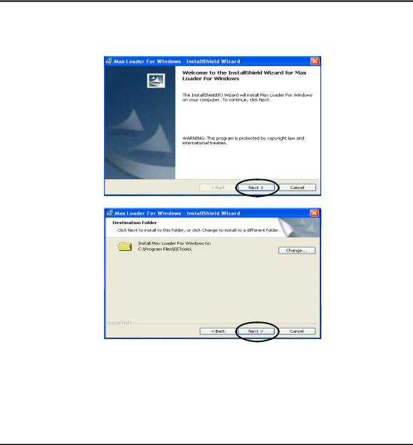
5.Set up MaxLoader software
6.Install MaxLoader and the MaxLoader icon and USB driver (eetusb.inf and eetusb.sys files) will be generated in directory C:\program files\EE Tools\.
Follow the steps below for installation for USB 2.0 driver.
13
MaxLoader User’s Guide
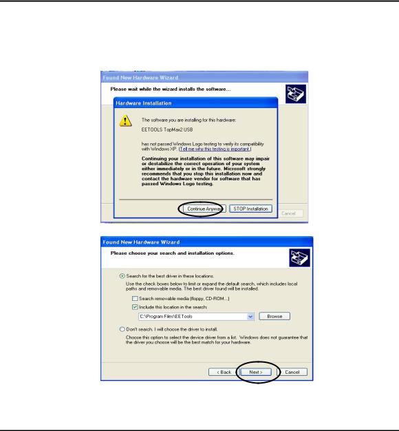
7.Connect a USB cable between programmer and your computer and turn the power switch ON after connecting the power cord in the programmer.
NOTE: In Windows2000, you need to choose “specific location” when the “Found New Hardware Wizard” appears. The USB driver files are generated
14
MaxLoader User’s Guide
in directory C:\program files\EE Tools. Or you can find the USB driver files in the CD-ROM comes in the product package.
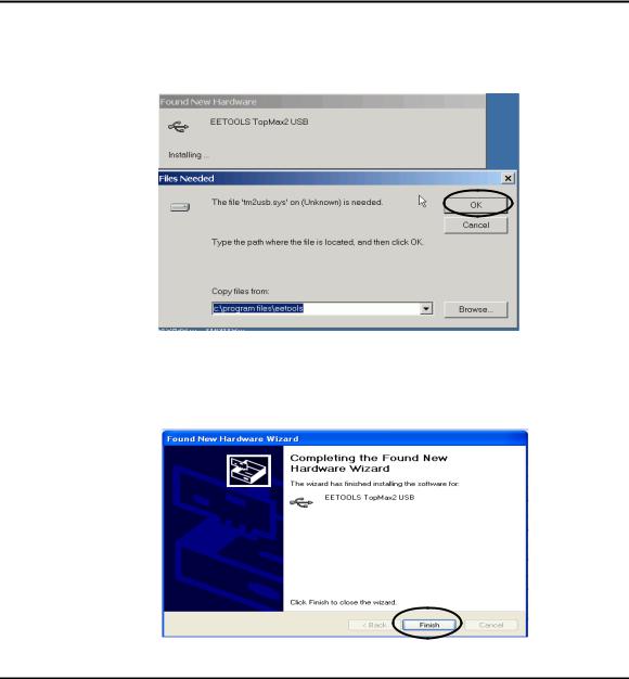
8.Click on the Finish button on the Wizard screen and you can confirm the USB driver in Device Manager in your computer system.
15

MaxLoader User’s Guide
NOTE: For a computer that doesn’t installed USB 2.0 controller, you need to install USB 2.0 driver for the particular product vendor.
9.Execute MaxLoader and choose Programmer model
10.Choose your programmer that is ready to be use in your computer.
16

MaxLoader User’s Guide
NOTE: Watch the model name in left-up corner screen and the ProMax4G(8G) won’t be ready if “DEMO mode” appears in the screen. Check the USB cable and turn on the AC switch in the back side of unit.
To install the Software for parallel port programmers
There are three different addresses for the parallel port. When you select an address from LPT1, LPT2, LPT3, one of them should be valid without a communication error message. Turn the AC switch ON before running the MaxLoader software. Make sure you connect the printer (IEEE) cable between TopMax/ChipMax and your available printer port and lock the shields in each side of the cable. Be sure that your programmer recognizes your computer’s parallel port address when you execute the MaxLoader icon. (MEMO mode is indicated that your programmer has a “communication error”)
1.Connect print cable between PC and programmer.
2.Connect AC cord to programmer.
3.Turn on AC switch located on the back side of TopMax
4.Install programmer software that comes in a CD-R (or download the latest software (all-in-one) from www.eetools.com
5.After the MaxLoader is installed, you choose a programmer name in the very first screen menu
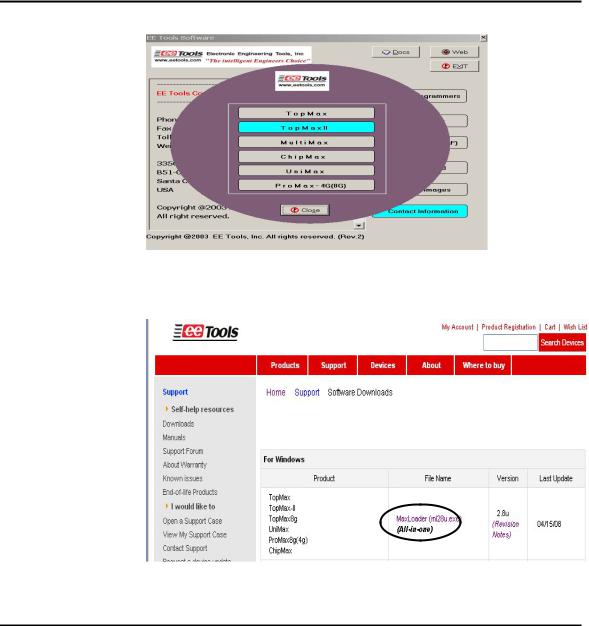
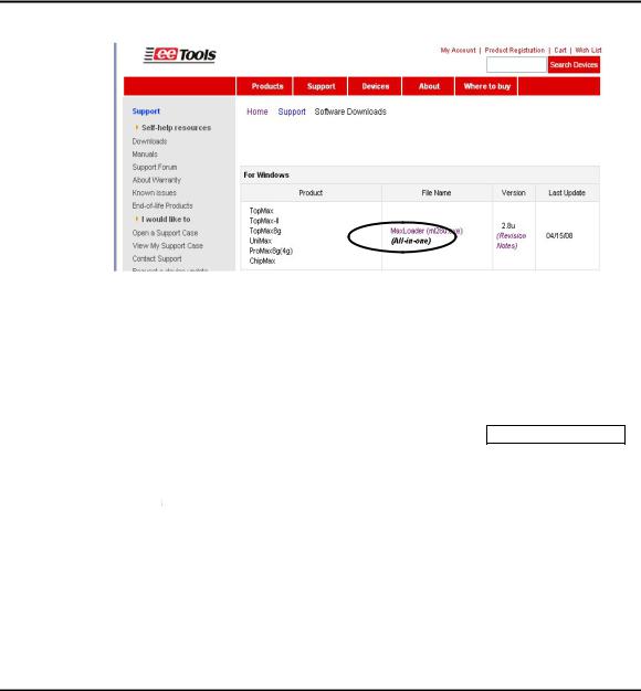
To download the software from the www.eetools.com web site
1.Click on “Software download” button on left at www.eetools.com and download MaxLoader software. The file will be saved to your hard disk. The MaxLoader can be operated for All-in-one (all programmers-in-one software).
2.Once the download is complete, double-click on the file name to install the software.
17
MaxLoader User’s Guide
NOTE: For the latest software upgrade, remove the old MaxLoader in “Add/Remove Program” of “Setting / Control Panel” in 2000/XP/VISTA before installing a new MaxLoader in your PC.
Select Product
After MaxLoader is installed, choose a programmer among TopMax, TopMax8G, ChipMax/ChipMax2, TopMaxII, UniMax, and ProMax8G (4G) hardware in the very first MaxLoader screen menu. Or Click on Config / Select product Make sure to select the right model and turn the switch on. (TopMaxII, ProMax, TopMax) or connect the AC cord (UniMax, ChipMax/ChipMax2)
Trouble Shooting In Installation
A communication error may occur on the screen if the hardware / software are not correctly installed.
Be sure that the following steps are checked:
Make sure the USB driver is installed after MaxLoader software is set up in PC.
18
MaxLoader User’s Guide
Make sure that the programmer hardware unit is connected to your PC printer port or USB port directly. A programmer for parallel port interface will not work with multiple port connectors.
Be sure your printer cable is firmly connected to your computer and the programmer. Plug in the AC power cord to your programmer and turn on the switch in the back of the unit before clicking on the MaxLoader icon.
NOTE: The MaxLoader detects the printer port address when you install the new software. When you see “Cannot find the programming module,” go to CONFIG/PORT and select all three parallel port addresses. If the same error message continues, contact technical support.
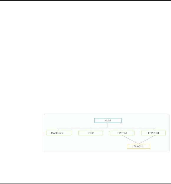
3. FAMILIES OF PROGRAMMABLE DEVICES
The devices that are supported on the EE Tools, Inc programmers are:
NVM: Non Volatile Memory
ROM: Read Only Memory
OTP: One Time Programmable ROM
EPROM: Erasable Programmable ROM
EEPROM: Electrically Erasable & Programmable ROM
NVM Hierarchy
19
MaxLoader User’s Guide
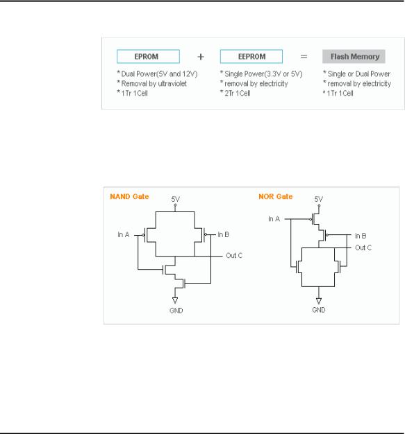
Flash Memory
Flash Memory Technologies
A |
B |
C(and) |
C(nand) |
|
A |
B |
C(or) |
C(nor) |
0 |
0 |
0 |
1 |
|
0 |
0 |
0 |
1 |
0 |
1 |
0 |
1 |
|
0 |
1 |
1 |
0 |
1 |
0 |
0 |
1 |
|
1 |
0 |
1 |
0 |
1 |
1 |
1 |
0 |
|
1 |
1 |
1 |
0 |
20
MaxLoader User’s Guide
Performance Comparison
* NAND Flash: High Wright Performance
Serial Flash EEPROM
The non-volatile Serial Flash Memory is widely used for code storage and user settings in cost-sensitive applications such as CD and DVD players, set-top- boxes (STB), digital-TV and cameras, graphic cards, printers, PC motherboards and flat panel displays. These products typically run their operating code from fast Random Access Memory (RAM), after downloading the code from the low-cost Serial Flash Memory at power-up. Several semiconductor manufacturers produce this device family named as 25xxx.
Serial EEPROM
These devices are electrically erasable, but they operate in a series rather than in parallel.
Xilinx 17xx family
From the Xilinx 17xx series, the RESET Polarity can be changed only on Xilinx 17xxD/L and 17128. On devices with EPROM portion already programmed or on new blank devices, RESET polarity is HIGH.
The current status of the Reset pin polarity is determined and displayed on the screen after Reading the device. The polarity of the Reset pin can ONLY be
21
MaxLoader User’s Guide
changed from HIGH to LOW, but not vice versa. To change the polarity, click on the Option button and check the Reset bit box before programming your device. To make certain that the RESET Polarity has been changed, read the device again. On the other serial EEPROM devices (but NOT Xilinx 17xxD/L & 17128) the RESET polarity is always HIGH and it cannot be changed to LOW.
Non-Typical Devices 8-bit 1-Megabits
There are four types of 1 Megabits EPROMS. One set has the A16 and OE lines swapped. However, this device will still program and verify like normal 1 Megabits. Once this device is placed into the circuit, it will appear as if it has not been programmed correctly. This is not due to the MaxLoader software or the programmer, but the difference between these 1 Megabits. When selecting a 1 Megabit, it is important to determine which one you have. Here is a list of 1 Megabits and their equivalents:
27010 (normal pin-out -- program as GENERIC or INTEL 27010):
Equivalents: INTEL 27010, HITACHI 27101, TOSHIBA 571000, NEC 271001, MITSUBISHI 27101, 27301 (non-standard pin-out -- program as HITACHI 27301's):
Equivalents: HITACHI 27301, NEC 271000, MITSUBISHI 27100, TOSHIBA 571001, INTEL 27C100
22
MaxLoader User’s Guide
16-bit 1-Megabits
Any devices with the number 27210, 271024 and the MITSUBISHI 27102. 27011: The 27011 is a 28-pin 1-megabit device that is organized into 8 pages of 16k-bytes. NOTE: The 27512 is 4 pages of 16k-bytes.
Erasing an EPROM
An EPROM has a quartz window located on the chip just above the die. Erasing an EPROM is done by exposing the EPROM to high-frequency ultra-violet (UV) light waves. Erasing an EPROM usually takes 15-20 minutes, but may be shorter or longer, depending on the device. If you wish to purchase an Eraser, call EE Tools at (408) 263-2221. When an EPROM is not being erased, the window may be covered with an opaque label. Sometimes (over a period of years) an EPROM will start to erase due to the rooms level of fluorescent light. Direct exposure to sunlight also has the same effect, but happens much more rapidly
.
PLD
A programmable logic device (PLD) consists of an array of logic gates and flipflops that can be programmed to implement an almost unlimited number of logic designs. These are programmable logic arrays that can be EEPROM based, EPROM based, fused link, anti-fuse, or Flash-based technology. They are programmable by the user to implement logic circuits in order to reduce part
23

MaxLoader User’s Guide
count and turnaround time. PLDs are programmed according to a fuse map, which is typically contained in a JEDEC file.
NOTE: PLD compiler CUPL EE Tools offers PLD development tool for engineers who want to generate a JEDEC file for data of PLD devices. Four different tools are available in www.eetools.com
PLD Features
Many different PLDs are available from the IC manufacturers. PLDs are fabricated using either bipolar or CMOS Processes. All PLDs are made up of combinations of AND gates, OR gates, inverters, and flip-flops.
PAL: The PAL is a PLD with a fuse-programmable AND array. The PAL’s AND gates connect to OR gates in a fixed pattern.
PROM: For many years, the PROM was not classified as a PLD, even
though most of the smaller PROMs (i.e. 32 x 8 organization) were being used as logic elements. The larger PROMs were still applied in bipolar microprocessor designs to store microcode instructions. The PROM has an architecture similar to the PAL, except that the PROM’s AND array is fixed while it’s OR array is programmable.
FPLA: The field-programmable logic array (FPLA) consists of a
programmable AND array like the PAL, with a programmable OR array like the PROM. The FPLA is therefore a more general PLD because any product term may be connected to any output OR gate. Because the entire IC is programmable, the FPLA can implement some functions which a PAL or PROM may not be able to implement.
EPLD: Several manufacturers produce PLDs which can be erased and
24

MaxLoader User’s Guide
reprogrammed like EPROMs. These ICs are called erasable programmable logic devices or EPLDs. Internally, they have the same programmable AND- OR-register structures of the PAL and FPLA.
Microcontroller
These devices are CPU's with on-chip EPROM and RAM. They are typically 40 pins and are UV erasable. They have part numbers such as Intel's 8748,8749,8751,8752 etc. A micro-controller is generally a computer-on-a-chip with RAM, ROM, and I/O ports. Microcontrollers are usually used for specific purposes, such as keyboard decoders, printers, clocks, telephones, CD-players, or any other application that requires a small, on-board computer. Microcontrollers are used to take the place of in-circuit logic, as it can be less expensive and take less space. Also, since it is software driven, the device may be updated very easily. Micro-controllers have the ability to use internal as well as external RAM. Also, micro-controller data may be encrypted or otherwise secured to prevent copying of the data or program information. Microcontrollers also have their own instruction set, usually very similar to familiar Microprocessors (such as the 8080 or 8086). The INTEL MCS-51 family features up to 64k each of internal and external memory, 32 I/O lines, interrupts, timers, and bit-addressable RAM. Its instruction set contains 111 instructions. However, for specific purposes, limited versions of the 51 family are available. For instance, the Philips 87c751/87c752 families do not allow external RAM to be used, and have limited I/O channels, etc. However, these devices still allow for data/program encryption and security levels. They are also less expensive than the MCS-51 micro-controllers.
See the help selection under MAIN-MENU COMMANDS for Encryption and Security-bit information.
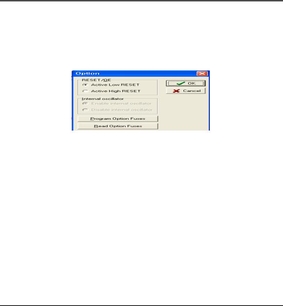
NOTE: Programming Microchip PIC family Microchip PIC series are different from other Microcontrollers in that they have an EPROM area as well as a Configuration Fuse. The Configuration Fuse in the
25

MaxLoader User’s Guide
PIC family is used to setup different Oscillator types, to set Memory Code
Protection and Watchdog timer, and etc. To program this fuse:
1.Program the EPROM portion of the device
2.Click on Option
3.Make any changes if necessary
4.Click on the Program Configuration Fuses button to program the fuse information that you want to program
5.Click on the Read Current Configuration Fuses button to read back the current status of the fuse
6.Press the Close button
About “Device ID” and “Auto Select” on EE Tools programmers
Most of the devices have their own manufacturer and device ID’s in each programmable devices such as E(E)PROM / Flash Memory, PLD, and MCU. However the old type of devices such as PAL, PROM, or 2816 does not come with an ID because the IC makers didn’t put its ID for the older chip types.
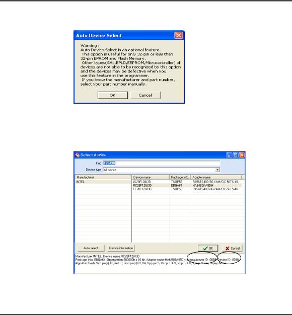
(Auto Select)
As you can see the “warning” in the Auto Select menu in MaxLoader, we can only guarantee the “auto select” function for 32-pin or less device in E(E)PROM / Flash Memory. Since device library in programmer software has information for these standard devices, users can utilize this feature as their purpose. However, all other devices such as PLD, Serial Memory, Microcontroller, and FPGA are not able to be recognized by programmer software automatically. We use this feature as optional device selection menu. Auto Select command allows you choose an unknown device through device IDs which were recorded in MaxLoader library. Put a device up to 32-pin on the ZIF socket of programmer and click on “Auto Select” in Select Device
26
MaxLoader User’s Guide
menu. It will find out a correct device ID and choose a correct device for you.
(To Find a Device ID)
After selecting a certain device from Select Device menu and plug-in a corresponding device in ZIF socket, you can see the ID(s) when you pressing “Shift” and “F1” keys in your keyboard.
27
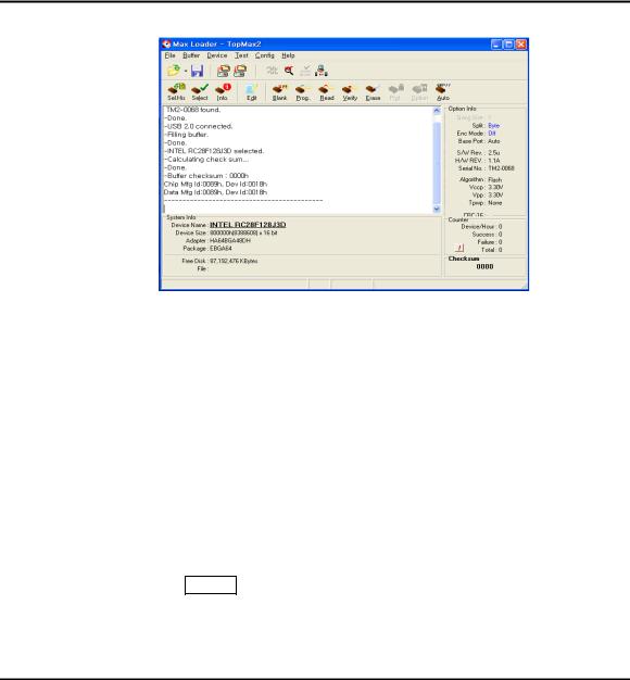
MaxLoader User’s Guide
In the software menu, Chip (in socket) MFG (manufacturer) ID and DATA (in software) ID must be identical if your target device is valid .
If it does not, check the socket with your device if you use NON-Standard (DIP) device or use test other devices in case the first device may be defective. This ID check must be passed before further operation on your device.
4. TERMS AND SYMBOLS USED IN THE GUIDE
Safety Note Conventions
NOTE assists the user in performing a task. It makes the job more easily understood.
CAUTION alerts the user that unexpected results or damages to a device may occur if an instruction is not followed.
Other terms and definitions are as follows
Toolbar : Clicking on a toolbar button manipulates operations or commands for MaxLoader programmer software.
Bold/Italics : actions items/software functions, i.e. Edit Button, IC Test, or Change Algorithm.
28

|
|
|
MaxLoader User’s Guide |
|
Device |
: |
The IC you are attempting to read, program, or verify. |
|
Buffer |
: |
The work area in your computer memory to execute Read, Save, |
|
Program, and Verify. The Buffer size may be from 64K to 32 Megabytes. |
||
NOTE: If the size of a device is bigger than the buffer size in your computer, MaxLoader will use the hard disk space (swapping). For this reason, the MaxLoader software can handle devices up to unlimited size of E(E)PROMs with your standard memory space ( a minimum of 512KB RAM memory is required).
Choosing a Right Adapter
Most programming adapters are simple package converters. They allow TSOP, QFP, SOIC, or PLCC devices to plug into the same device’s DIP footprint. These adapters are available for memory, logic, and Microcontrollers. They can often be used with many devices from various manufacturers. For devices that cannot use a generic footprint we have offered adapters to work with specific programmers.
Here is what you need to know to select an appropriate adapter.
1)A part number and manufacturer of your device.
2)A device package. (TSOP, PLCC, DIP, QFP, SOIC, etc.) (Refer to the following package drawings)
3)Pin numbers in your device.
4)In some cases you need to know your device package dimensions for SOIC, SSOP, and TSOP packages.
29
MaxLoader User’s Guide
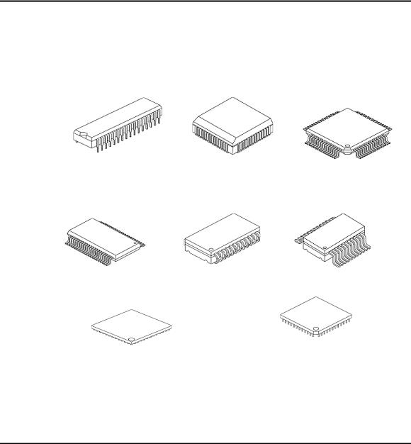
Different Device Packages
DIP |
PLCC |
QFP |
TSOP |
SOJ |
SOIC |
BGA |
PGA |
30
 Loading...