


 Loading...
6400 Line Matrix Printers
nt n n n m t n n
Cabinet and Pedestal Models
Form Number S246±0117±06
©Copyright IBM Corp., 1995, 1998

|
|
|
|
|
|
|
|
|
|
|
|
S246±0117±06 |
|
|
|
|
|
|
|
|
|
|
|
||
|
|
|
|
|
|
|
|
|
|
|
||
|
|
|
|
|
|
|
|
|
|
|
||
|
|
|
|
|
|
|
|
|
|
|
|
|
|
|
|
|
|
|
|
|
|
|
|
|
|
nt n n n m t n n
b d d l d l
Note!
Before using the information and the product it works with, make sure you read the general information under ªNotices,º located right after the Table of Contents.
Seventh Edition (October 1998)
This edition applies to the 6400 Line Matrix Printer.
The following paragraph does not apply to any other country where such provisions are inconsistent with local law:
INTERNATIONAL BUSINESS MACHINES CORPORATION PROVIDES THIS PUBLICATION ªAS ISº WITHOUT WARRANTY OF ANY KIND, EITHER EXPRESS OR IMPLIED, INCLUDING, BUT NOT LIMITED TO, THE IMPLIED WARRANTIES OF MERCHANTABILITY OR FITNESS FOR A PARTICULAR PURPOSE. Some states do not allow disclaimer of express or implied warranties
in certain transactions; therefore, this statement may not apply to you.
Requests for IBM publications should be made to your IBM representative or to the IBM branch office serving your locality. Publications are not stocked at the address given below.
IBM welcomes your comments about this publication. You may send your comments by facsimile to 1±800±524±1519, by E-mail to print_pubs@vnet.ibm.com, or by mail to:
IBM Printing Systems Company
Information Development
Department H7FE, Building 003G
P.O. Box 1900
Boulder, CO 80301±9191, U.S.A.
When you send information to IBM or IBM Printing Systems Company, you grant a nonexclusive right to use or distribute the information in any way IBM or IBM Printing Systems Company believes appropriate without incurring any obligation to you.
Copyright International Business Machines Corporation 1995, 1998.
All rights reserved.
Note to U.S. Government UsersÐDocumentation related to restricted rightsÐUse, duplication or disclosure is subject to restrictions set forth in GSA ADP Schedule Contract with IBM Corp.
Table of Contents
1 Maintenance Overview
About the Printer . . . . . . . . . . . . . . . . . . . . . . . . . . . . . . . . . . . . . . . . . . . . . . . . . . . . 13 The IBM 6400 Series Printer Family . . . . . . . . . . . . . . . . . . . . . . . . . . . . . . . 13 Printer Evolution . . . . . . . . . . . . . . . . . . . . . . . . . . . . . . . . . . . . . . . . . . . . . . . . 15 How to Identify the Printer . . . . . . . . . . . . . . . . . . . . . . . . . . . . . . . . . . . . . . . . 15 Important Maintenance Notes . . . . . . . . . . . . . . . . . . . . . . . . . . . . . . . . . . . . . 16
About This Manual . . . . . . . . . . . . . . . . . . . . . . . . . . . . . . . . . . . . . . . . . . . . . . . . . . 16 How to Use This Manual . . . . . . . . . . . . . . . . . . . . . . . . . . . . . . . . . . . . . . . . . 16 Notes and Notices . . . . . . . . . . . . . . . . . . . . . . . . . . . . . . . . . . . . . . . . . . . . . . . 16 Printing Conventions in This Manual . . . . . . . . . . . . . . . . . . . . . . . . . . . . . . . 18 Related Documents . . . . . . . . . . . . . . . . . . . . . . . . . . . . . . . . . . . . . . . . . . . . . . 18
Controls and Indicators . . . . . . . . . . . . . . . . . . . . . . . . . . . . . . . . . . . . . . . . . . . . . . 20 Electrical Controls and Indicators . . . . . . . . . . . . . . . . . . . . . . . . . . . . . . . . . . 20 Mechanical Controls and Indicators . . . . . . . . . . . . . . . . . . . . . . . . . . . . . . . . 24 Tools, Test Equipment, and Supplies . . . . . . . . . . . . . . . . . . . . . . . . . . . . . . . . . . . 26
2
3
Installation
Installation . . . . . . . . . . . . . . . . . . . . . . . . . . . . . . . . . . . . . . . . . . . . . . . . . . . . . . . . . |
27 |
Preventive Maintenance
Cleaning the Printer . . . . . . . . . . . . . . . . . . . . . . . . . . . . . . . . . . . . . . . . . . . . . . . . . 29 Cleaning the Exterior . . . . . . . . . . . . . . . . . . . . . . . . . . . . . . . . . . . . . . . . . . . . 30 Cleaning the Interior . . . . . . . . . . . . . . . . . . . . . . . . . . . . . . . . . . . . . . . . . . . . . 30 Cleaning the Shuttle Frame Assembly . . . . . . . . . . . . . . . . . . . . . . . . . . . . . . 31 Cleaning the Card Cage Fan Assembly . . . . . . . . . . . . . . . . . . . . . . . . . . . . 33
4 Principles of Operation
Line Matrix Printing . . . . . . . . . . . . . . . . . . . . . . . . . . . . . . . . . . . . . . . . . . . . . . . . . . 35
Printing Mechanism . . . . . . . . . . . . . . . . . . . . . . . . . . . . . . . . . . . . . . . . . . . . . . . . . 38
Shuttle Frame Assembly . . . . . . . . . . . . . . . . . . . . . . . . . . . . . . . . . . . . . . . . . 38
Paper Transport System . . . . . . . . . . . . . . . . . . . . . . . . . . . . . . . . . . . . . . . . . . 41
Ribbon Transport System . . . . . . . . . . . . . . . . . . . . . . . . . . . . . . . . . . . . . . . . . 42
Logical Control of the Printer . . . . . . . . . . . . . . . . . . . . . . . . . . . . . . . . . . . . . . . . . 43
Operator Panel . . . . . . . . . . . . . . . . . . . . . . . . . . . . . . . . . . . . . . . . . . . . . . . . . . . . . 44
CMX Controller Board . . . . . . . . . . . . . . . . . . . . . . . . . . . . . . . . . . . . . . . . . . . . . . . 45
Data Controller . . . . . . . . . . . . . . . . . . . . . . . . . . . . . . . . . . . . . . . . . . . . . . . . . . 47
Engine Controller . . . . . . . . . . . . . . . . . . . . . . . . . . . . . . . . . . . . . . . . . . . . . . . . 50
Power Supply Board . . . . . . . . . . . . . . . . . . . . . . . . . . . . . . . . . . . . . . . . . . . . . . . . . 51
Printer Interface . . . . . . . . . . . . . . . . . . . . . . . . . . . . . . . . . . . . . . . . . . . . . . . . . . . . . 52
Graphics . . . . . . . . . . . . . . . . . . . . . . . . . . . . . . . . . . . . . . . . . . . . . . . . . . . . . . . . . . . 53
5 Troubleshooting
Introduction . . . . . . . . . . . . . . . . . . . . . . . . . . . . . . . . . . . . . . . . . . . . . . . . . . . . . . . . 55
Troubleshooting Aids . . . . . . . . . . . . . . . . . . . . . . . . . . . . . . . . . . . . . . . . . . . . . . . . 55
Start of Call . . . . . . . . . . . . . . . . . . . . . . . . . . . . . . . . . . . . . . . . . . . . . . . . . . . . . . . . 56
Troubleshooting Display Messages . . . . . . . . . . . . . . . . . . . . . . . . . . . . . . . . . . . . 57
Message List . . . . . . . . . . . . . . . . . . . . . . . . . . . . . . . . . . . . . . . . . . . . . . . . . . . . . . . 58
Troubleshooting Other Symptoms . . . . . . . . . . . . . . . . . . . . . . . . . . . . . . . . . . . . . 66
General Symptom List . . . . . . . . . . . . . . . . . . . . . . . . . . . . . . . . . . . . . . . . . . . . . . . 67
Troubleshooting Procedures . . . . . . . . . . . . . . . . . . . . . . . . . . . . . . . . . . . . . . . . . . 70
Operator Print Tests . . . . . . . . . . . . . . . . . . . . . . . . . . . . . . . . . . . . . . . . . . . . . . . . . 135
Selecting and Running Operator Print Tests . . . . . . . . . . . . . . . . . . . . . . . . . 137 Customer Engineer (CE) Tests . . . . . . . . . . . . . . . . . . . . . . . . . . . . . . . . . . . . . . . . 138 Selecting and Running Customer Engineer Tests . . . . . . . . . . . . . . . . . . . . 140 Boot Diagnostics Menu . . . . . . . . . . . . . . . . . . . . . . . . . . . . . . . . . . . . . . . . . . . 142 Hex Code Printout . . . . . . . . . . . . . . . . . . . . . . . . . . . . . . . . . . . . . . . . . . . . . . . . . . 145 Printer Information Menu . . . . . . . . . . . . . . . . . . . . . . . . . . . . . . . . . . . . . . . . . . . . . 148 Displaying Printer Information . . . . . . . . . . . . . . . . . . . . . . . . . . . . . . . . . . . . . 149 Soft vs. Hard Reset . . . . . . . . . . . . . . . . . . . . . . . . . . . . . . . . . . . . . . . . . . . . . . . . . 150 The Power On Sequence . . . . . . . . . . . . . . . . . . . . . . . . . . . . . . . . . . . . . . . . . . . . 151
6 Adjustment Procedures
Introduction . . . . . . . . . . . . . . . . . . . . . . . . . . . . . . . . . . . . . . . . . . . . . . . . . . . . . . . . 157 Preparing the Printer for Maintenance . . . . . . . . . . . . . . . . . . . . . . . . . . . . . . . . . 158 Returning the Printer to Normal Operation . . . . . . . . . . . . . . . . . . . . . . . . . . . . . . 159 Belt, Paper Feed Timing, Adjustment . . . . . . . . . . . . . . . . . . . . . . . . . . . . . . . . . . 160 Belt, Platen Open, Adjustment . . . . . . . . . . . . . . . . . . . . . . . . . . . . . . . . . . . . . . . . 162 Paper Drive Motor Pulley Alignment . . . . . . . . . . . . . . . . . . . . . . . . . . . . . . . . . . . 164 Paper Scale Alignment . . . . . . . . . . . . . . . . . . . . . . . . . . . . . . . . . . . . . . . . . . . . . . 166 Platen Gap Adjustment . . . . . . . . . . . . . . . . . . . . . . . . . . . . . . . . . . . . . . . . . . . . . . 168 Platen Open Motor Pulley Alignment . . . . . . . . . . . . . . . . . . . . . . . . . . . . . . . . . . . 170 Ribbon Guide Alignment . . . . . . . . . . . . . . . . . . . . . . . . . . . . . . . . . . . . . . . . . . . . . 172 Splined Shaft Skew Adjustment . . . . . . . . . . . . . . . . . . . . . . . . . . . . . . . . . . . . . . . 174 Adjusting the End of Forms Distance . . . . . . . . . . . . . . . . . . . . . . . . . . . . . . . . . . 175 Hammer Phasing . . . . . . . . . . . . . . . . . . . . . . . . . . . . . . . . . . . . . . . . . . . . . . . . . . . 179 Loading Flash Memory . . . . . . . . . . . . . . . . . . . . . . . . . . . . . . . . . . . . . . . . . . . . . . 181 Coil Temperature Adjustment . . . . . . . . . . . . . . . . . . . . . . . . . . . . . . . . . . . . . . . . . 188 Set Shuttle Speed . . . . . . . . . . . . . . . . . . . . . . . . . . . . . . . . . . . . . . . . . . . . . . . . . . . 189
7 Replacement Procedures and Illustrated Parts List
Organization of This Chapter . . . . . . . . . . . . . . . . . . . . . . . . . . . . . . . . . . . . . . . . . |
191 |
Section I: Replacement Procedures
Preparing the Printer for Maintenance . . . . . . . . . . . . . . . . . . . . . . . . . . . . . . . . . 194 Belt, Paper Feed Timing . . . . . . . . . . . . . . . . . . . . . . . . . . . . . . . . . . . . . . . . . . . . . 195 Belt, Platen Open . . . . . . . . . . . . . . . . . . . . . . . . . . . . . . . . . . . . . . . . . . . . . . . . . . . 197 Cable Connectors and Connector Shells . . . . . . . . . . . . . . . . . . . . . . . . . . . . . . . 198 Circuit Board: Controller . . . . . . . . . . . . . . . . . . . . . . . . . . . . . . . . . . . . . . . . . . . . . 200 Circuit Board: Power Supply . . . . . . . . . . . . . . . . . . . . . . . . . . . . . . . . . . . . . . . . . . 203 Circuit Breaker . . . . . . . . . . . . . . . . . . . . . . . . . . . . . . . . . . . . . . . . . . . . . . . . . . . . . . 204 Coax/Twinax Multi-Platform Interface . . . . . . . . . . . . . . . . . . . . . . . . . . . . . . . . . . 205 Cover Assembly, Hammer Bank / Ribbon Mask . . . . . . . . . . . . . . . . . . . . . . . . . 206 Cover Assembly, Shuttle . . . . . . . . . . . . . . . . . . . . . . . . . . . . . . . . . . . . . . . . . . . . . 209 Cover Assembly, Top, Pedestal Model . . . . . . . . . . . . . . . . . . . . . . . . . . . . . . . . . 210 Doors, Cabinet, Reversal . . . . . . . . . . . . . . . . . . . . . . . . . . . . . . . . . . . . . . . . . . . . 211 Ethernet Interface Assemblies . . . . . . . . . . . . . . . . . . . . . . . . . . . . . . . . . . . . . . . . 212
Fan Assembly, Cabinet Exhaust . . . . . . . . . . . . . . . . . . . . . . . . . . . . . . . . . . . . . . 215
Fan Assembly, Card Cage . . . . . . . . . . . . . . . . . . . . . . . . . . . . . . . . . . . . . . . . . . . 216
Fan Assembly, Hammer Bank . . . . . . . . . . . . . . . . . . . . . . . . . . . . . . . . . . . . . . . . 217
Hammer Spring Assembly . . . . . . . . . . . . . . . . . . . . . . . . . . . . . . . . . . . . . . . . . . . . 218
IBM Coax/Twinax Expansion Board . . . . . . . . . . . . . . . . . . . . . . . . . . . . . . . . . . . 222
Magnetic Pick-up (MPU) Assembly . . . . . . . . . . . . . . . . . . . . . . . . . . . . . . . . . . . . 223
Memory Modules and Security PAL . . . . . . . . . . . . . . . . . . . . . . . . . . . . . . . . . . . . 224
Motor Assembly, Paper Feed . . . . . . . . . . . . . . . . . . . . . . . . . . . . . . . . . . . . . . . . . 227
Motor Assembly, Platen Open . . . . . . . . . . . . . . . . . . . . . . . . . . . . . . . . . . . . . . . . 229
Motor Assembly, Ribbon Drive . . . . . . . . . . . . . . . . . . . . . . . . . . . . . . . . . . . . . . . . 231
Network Print Server . . . . . . . . . . . . . . . . . . . . . . . . . . . . . . . . . . . . . . . . . . . . . . . . 232
Operator Panel Assembly, Cabinet Model . . . . . . . . . . . . . . . . . . . . . . . . . . . . . . 233
Operator Panel Assembly, Pedestal Model . . . . . . . . . . . . . . . . . . . . . . . . . . . . . 234
Paper Guide Assembly . . . . . . . . . . . . . . . . . . . . . . . . . . . . . . . . . . . . . . . . . . . . . . 235
Paper Ironer . . . . . . . . . . . . . . . . . . . . . . . . . . . . . . . . . . . . . . . . . . . . . . . . . . . . . . . . 236
Platen . . . . . . . . . . . . . . . . . . . . . . . . . . . . . . . . . . . . . . . . . . . . . . . . . . . . . . . . . . . . . 237
Resistors, Terminating . . . . . . . . . . . . . . . . . . . . . . . . . . . . . . . . . . . . . . . . . . . . . . . 242
Ribbon Guide Assembly (L/R) . . . . . . . . . . . . . . . . . . . . . . . . . . . . . . . . . . . . . . . . 244
Ribbon Hub . . . . . . . . . . . . . . . . . . . . . . . . . . . . . . . . . . . . . . . . . . . . . . . . . . . . . . . . 245
Security Module . . . . . . . . . . . . . . . . . . . . . . . . . . . . . . . . . . . . . . . . . . . . . . . . . . . . 224
Shaft, Splined . . . . . . . . . . . . . . . . . . . . . . . . . . . . . . . . . . . . . . . . . . . . . . . . . . . . . . 246
Shaft, Support . . . . . . . . . . . . . . . . . . . . . . . . . . . . . . . . . . . . . . . . . . . . . . . . . . . . . . 248
Shuttle Frame Assembly . . . . . . . . . . . . . . . . . . . . . . . . . . . . . . . . . . . . . . . . . . . . . 249
Spring Assembly, Gas . . . . . . . . . . . . . . . . . . . . . . . . . . . . . . . . . . . . . . . . . . . . . . . 251
Spring, Extension . . . . . . . . . . . . . . . . . . . . . . . . . . . . . . . . . . . . . . . . . . . . . . . . . . . 252
Switch Assembly, Cover Open . . . . . . . . . . . . . . . . . . . . . . . . . . . . . . . . . . . . . . . . 253
Switch Assembly, Paper Detector . . . . . . . . . . . . . . . . . . . . . . . . . . . . . . . . . . . . . 254
Switch Assembly, Platen Interlock . . . . . . . . . . . . . . . . . . . . . . . . . . . . . . . . . . . . . 256
Tractor (L/R) . . . . . . . . . . . . . . . . . . . . . . . . . . . . . . . . . . . . . . . . . . . . . . . . . . . . . . . 258
Section II: Illustrated Parts List
Figure 39. Top Cover, Doors, and Casters, Cabinet Model . . . . . . . . . . . . . . . . 261 Figure 40. Paper Stacker and Chains . . . . . . . . . . . . . . . . . . . . . . . . . . . . . . . . . . 263 Figure 41. Control Panel and Cabinet Details . . . . . . . . . . . . . . . . . . . . . . . . . . . 265 Figure 42. Pedestal Details . . . . . . . . . . . . . . . . . . . . . . . . . . . . . . . . . . . . . . . . . . . 267 Figure 43. Inside Covers, Cabinet Model . . . . . . . . . . . . . . . . . . . . . . . . . . . . . . . 269 Figure 44. Inside Covers and Card Cage, Pedestal Models . . . . . . . . . . . . . . . 271
Figure 44a. Card Cage Detail, Pedestal Models . . . . . . . . . . . . . . . . . . . . . . . . . 273 Figure 45. Print Mechanism and Circuit Boards: Early Models . . . . . . . . . . . . . 275 Figure 46. Print Mechanism and Circuit Boards: Later Models . . . . . . . . . . . . . 277 Figure 47. Magnetic Pickup Unit (MPU) and Extension Spring . . . . . . . . . . . . 279 Figure 48. Tractor Shafts . . . . . . . . . . . . . . . . . . . . . . . . . . . . . . . . . . . . . . . . . . . . . 281 Figure 49. Platen . . . . . . . . . . . . . . . . . . . . . . . . . . . . . . . . . . . . . . . . . . . . . . . . . . . . 283 Figure 50. Motors, Card Cage Fan, and Paper Detector Switch . . . . . . . . . . . 285 Figure 51. Circuit Breaker . . . . . . . . . . . . . . . . . . . . . . . . . . . . . . . . . . . . . . . . . . . . 287 Figure 52. IBM Coax/Twinax Expansion Board . . . . . . . . . . . . . . . . . . . . . . . . . . 289 Figure 53. PrintNet Ethernet Interface Assemblies . . . . . . . . . . . . . . . . . . . . . . . 291
Appendices |
|
|
A |
Wire Data . . . . . . . . . . . . . . . . . . . . . . . . . . . . . . . . . . . . . . . . . . . . . . . . |
293 |
B |
Printer Specifications . . . . . . . . . . . . . . . . . . . . . . . . . . . . . . . . . . . |
333 |
C |
Metric Conversion Tables . . . . . . . . . . . . . . . . . . . . . . . . . . . . . . |
345 |
D |
Torque Table . . . . . . . . . . . . . . . . . . . . . . . . . . . . . . . . . . . . . . . . . . . . . |
347 |
E |
Safety Inspection Guide . . . . . . . . . . . . . . . . . . . . . . . . . . . . . . . . |
349 |
F |
Abbreviations and Signal Mnemonics . . . . . . . . . . . . . . . . . |
357 |
G |
Cords and Adapters . . . . . . . . . . . . . . . . . . . . . . . . . . . . . . . . . . . . |
365 |
H |
Part Numbers . . . . . . . . . . . . . . . . . . . . . . . . . . . . . . . . . . . . . . . . . . . . |
367 |
I |
Noise Suppression Devices . . . . . . . . . . . . . . . . . . . . . . . . . . . . |
375 |
J |
SureStak Power Stacker . . . . . . . . . . . . . . . . . . . . . . . . . . . . . . . . |
377 |
Index . . . . . . . |
. . . . . . . . . . . . . . . . . . . . . . . . . . . . . . . . . . . . . . . . . . . . . . . . . . . . . . . . . . . . . |
413 |

ENERGY STAR
The EPA ENERGY STAR** Computers program is a partnership effort with manufacturers of data processing equipment to promote the introduction of energy-efficient personal computers, monitors, and printers, and to reduce air pollution caused by power generation.
IBM participates in this program by introducing printers that reduce power consumption when they are not being used. This feature can cut energy use by up to 50 percent.
Note: The ENERGY STAR emblem does not represent EPA endorsement of any product or service.
Notices
References in this publication to IBM products, programs, or services do not imply that IBM intends to make these available in all countries in which IBM operates. Any reference to an IBM licensed product, program, or service is not intended to state or imply that only IBM's product, program, or service may be used. Any functionally equivalent product, program, or service that does not infringe any of IBM's intellectual property rights may be used instead of the IBM product. Evaluation and verification of operation in conjunction with other products, except those expressly designated by IBM, is the user's responsibility.
Any performance data contained in this document was obtained in a controlled environment based on the use of specific data. The results that may be obtained in other operating environments may vary significantly. Users of this document should verify the applicable data in their specific environment. Therefore, such data does not constitute a performance guarantee or warranty.
IBM may have patents or pending patent applications covering subject matter in this document. The furnishing of this document does not give you any license to these patents. You can send license inquiries, in writing, to the IBM Corporation, IBM Director of Licensing, 208 Harbor Drive, Stamford, Connecticut, United States, 06904.
Electrical Safety
This printer is inspected and listed by recognized national testing laboratories, such as Underwriters Laboratories, Inc. (UL) in the U.S.A. and Canadian Standards Association (CSA) in Canada. Listing of a product by a national testing laboratory indicates that the product is designed and manufactured in accordance with national requirements intended to minimize safety hazards. IBM equipment meets a very high standard of safety in design and manufacture. Remember,
however, that this product operates under conditions of high electrical potentials and heat generation, both of which are functionally necessary.
Trademarks and Service Marks
The following terms, denoted by an asterisk (*) in this publication, are trademarks of the IBM Corporation in the United States or other countries or both.
IBM
PC-DOS
SCS
Token-Ring
The following terms, denoted by a double asterisk (**) in this publication, are trademarks of other companies:
Acrobat |
Adobe Systems Incorporated |
Adobe |
Adobe Systems Incorporated |
Code V |
Quality Micro Systems |
ECOS |
ECOS Electronics Corp., Inc., Oak Park, Ill. |
ENERGY STAR |
United States Environmental Protection Agency |
Epson |
Epson Seiko Corporation |
Ethernet |
Xerox Corporation |
Fluke |
John Fluke Manufacturing Co., Inc. |
FX |
Epson Seiko Corporation |
IGP |
Printronix, Inc. |
MS-DOS |
Microsoft Corporation |
PrintNet |
Printronix, Inc. |
Printronix |
Printronix, Inc. |
SureStack |
Printronix, Inc. |
Torx |
Camcar/Textron Inc. |
Safety Notices
Danger and Caution notices are numbered to help you find the translated versions in the IBM 6400 Line Matrix Printer Safety Notices booklet.
|
DANGER: |
|
|
<2> |
Switch off printer power and unplug the printer power cord before |
|
cleaning the printer. |
<3> |
Hazardous voltages are present in the printer with the power cord |
|
connected to the power source. Switch off printer power and unplug the |
|
printer power cord before proceeding. |
<4> |
Do not connect or disconnect any communication port, teleport, |
|
attachment connector, or power cord during an electrical storm. |
<5> |
Power off the printer and disconnect the power cord before connecting |
|
or disconnecting communication port, teleport, or attachment cable |
|
connector. |
|
|
CAUTION:
<2> Over time the upper edge of the paper ironer can become sharp. To avoid cutting yourself handle the paper ironer on the sides.
<4> To prevent injury from electric shock, wait at least one minute after powering off before removing the power supply circuit board.
<5> The constant force spring is a high tension spring. To avoid pinching your fingers, coil the spring slowly and carefully. Do not let the spring twist or crimp.

1 Maintenance Overview
About the Printer
The entire system architecture of an IBM* 6400 line matrix printer is contained on one circuit board. The use of DRAM and flash memory on this board permits rapid access to stored printer emulations and fast processing of print data. A variable-speed shuttle and half-step paper control enables the printer to print a wide variety of high-volume jobs with minimum maintenance and maximum reliability.
Although technologically advanced, the printer is easy to use. The operator can select every printer function at the control panel or by sending printer control codes in the data stream from the host computer.
This is also an excellent graphics printer, with optional features that simplify the creation of dot images. The IGP** and Code V** Printronix** emulations are simple but versatile graphics programming languages that load into flash memory.
The IBM 6400 Series Printer Family
The IBM 6400 Line Matrix Printer family consists of pedestal mount and floor cabinet models that print at different speeds, as shown in Table 1. The print speeds listed in Table 1 are the maximum speeds attainable under certain conditions. Actual print speed is determined by the interaction of many variables. For more information, refer to the discussion of Printing Rates in Appendix B, page 342.
Maintenance Overview |
13 |
Models that print 475, 500, 800, 900, and 1000 lpm are available in floor cabinet and pedestal housings. Models that print 1200, 1400, and 1500 lpm are available only in floor cabinets.
Table 1. The IBM 6400 Series Printer Family
Model |
Enclosure |
Hammer |
Data Controller |
|
Number |
Speed |
|
Bank |
Clock1 |
6400±004 |
475 lpm |
Cabinet |
28 Hammers |
25 MHz |
|
|
|
|
|
6400±04P |
475 lpm |
Pedestal |
28 Hammers |
25 MHz |
|
|
|
|
|
6400±005 |
500 lpm |
Cabinet |
28 Hammers |
25 MHz |
|
|
|
|
|
6400±05P |
500 lpm |
Pedestal |
28 Hammers |
25 MHz |
|
|
|
|
|
6400±050 |
500 lpm |
Cabinet |
28 Hammers |
40 MHz |
|
|
|
|
|
6400±P50 |
500 lpm |
Pedestal |
28 Hammers |
40 MHz |
|
|
|
|
|
6400±008 |
800 lpm |
Cabinet |
49 Hammers |
25 MHz |
|
|
|
|
|
6400±08P |
800 lpm |
Pedestal |
49 Hammers |
25 MHz |
|
|
|
|
|
6400±009 |
900 lpm |
Cabinet |
49 Hammers |
25 MHz |
|
|
|
|
|
6400±09P |
900 lpm |
Pedestal |
49 Hammers |
25 MHz |
|
|
|
|
|
6400±010 |
1000 lpm |
Cabinet |
60 Hammers |
40 MHz |
|
|
|
|
|
6400±P10 |
1000 lpm |
Pedestal |
60 Hammers |
40 MHz |
|
|
|
|
|
6400±012 |
1200 lpm |
Cabinet |
91 Hammers |
25 MHz |
|
|
|
|
|
6400±014 |
1400 lpm |
Cabinet |
91 Hammers |
40 MHz |
|
|
|
|
|
6400±015 |
1500 lpm |
Cabinet |
102 Hammers |
40 MHz |
|
|
|
|
|
1 The microprocessor of the Data Controller unit on the CMX controller board runs at 25 MHz or 40 MHz, depending on printer model. This means there are two kinds of CMX controller board for IBM 6400 printers, used as shown in Table 1. The 40 MHz controller board, however, is backwards compatible in all models that use the 25 MHz board.
14 |
Maintenance Overview |
Printer Evolution
IBM 6400±050, ±P50, ±010, ±P10, and ±015 printers use a redesigned shuttle frame assembly, hammer bank, and ribbon guides which are not compatible with earlier models. These models use the CMX 040 controller board, which has a 40 MHz clock speed on the Data Controller unit.
How to Identify the Printer
The model number of the printer indicates printer family, speed, and type of enclosure. (See Figure 1.)
|
Speed Rating: |
||
|
004 |
= 475 lpm |
|
|
005 |
= 500 lpm (25 MHz controller) |
|
|
050 |
= 500 lpm (40 MHz controller) |
|
|
008 |
= 800 lpm |
|
IBM 6400 Printer Family |
009 = 900 lpm |
||
|
010 |
= 1000 lpm |
|
|
012 |
= 1200 lpm |
|
6400±04P |
014 |
= 1400 lpm |
|
015 |
= 1500 lpm |
||
|
|||
Enclosure Code*:
P = Pedestal Model
* No Code = Cabinet Model
Figure 1. Interpreting the Printer Model Number
Maintenance Overview |
15 |

Important Maintenance Notes
ATTENTION
Failure to observe the following guidelines can result in damage to the equipment.
To ensure the best performance of the printer, remember these important maintenance concepts when you service the printer:
♦Do not adjust the platen gap unless the original shuttle frame assembly or platen has been replaced with a new or rebuilt unit, or unless instructed to do so in the troubleshooting chapter.
♦Never bend or ªtweakº hammer springs. Always handle hammer springs by the thick mounting base. The hammer springs and hammer tips are delicate and precisely aligned.
♦Use only the ribbons specified in Appendix B. Use of incorrect ribbons can lead to ink migration problems, degraded print quality, and expensive damage to the printer.
♦Do not close the forms thickness lever too tightly. Closing the forms thickness lever too tightly can lead to smearing, degraded print quality, paper jams, and damage to the platen and shuttle assembly.
About This Manual
This is a field service maintenance manual. It is designed so that you can quickly locate maintenance information.
How to Use This Manual
1.Find the procedure or information you need in the Table of Contents or the Index.
2.Read the entire procedure before you do it.
3.Gather the parts and tools you will need.
4.Make sure you understand all safety notices before you start a task. Notes and notices are defined below.
16 |
Maintenance Overview |
Notes and Notices
For your safety and to protect valuable equipment, it is very important that you read and comply with all information highlighted under notes and notices:
DANGER:
The word Danger indicates the presence of a hazard that has the potential of causing death or serious personal injury. Danger and Caution notices are numbered to help you find the translated versions in the IBM 6400 Line Matrix Printer Safety Notices booklet.
CAUTION:
The word Caution indicates the presence of a hazard that has the potential of causing moderate or minor personal injury.
CAUTION:
This symbol indicates an assembly that requires two or more persons to lift or hold.
ATTENTION
Indicates the possibility of damage to a program, device, system, or data.
IMPORTANT
Information vital to proper operation of the printer.
NOTE: A note gives you helpful tips about printer operation and maintenance.
Maintenance Overview |
17 |
Printing Conventions in This Manual
♦Operator panel keys and indicators are printed bold. Example: Press the Cancel key, then press the Start key.
♦Liquid Crystal Display (LCD) messages are printed in capital letters inside quotation marks ( ª º ).
Example: Press the Stop key. ªNOT READYº appears on the LCD.
♦Key combinations are denoted by the + (plus) symbol.
Example: Press Scroll" + Scroll
means Press the Scroll" key and the Scroll key at the same time.
Related Documents
To ensure complete understanding of important safety notices for technicians whose native language is not English, the notices have been translated into many languages in the IBM 6400 Line Matrix Printer Safety Notices: Form No. G544±5389.
This maintenance manual does not explain how to operate or configure the printer. For that information, refer to the Operator's Guide and Setup Guide:
♦IBM 6400 Line Matrix Printer Operator's Guide, Form No. S544±5641 Illustrated instructions on daily printer operation.
♦IBM 6400 Line Matrix Printer Setup Guide, Form No. S544±5640 Explains how to install and configure the printer.
♦Coax/Twinax Multi-Platform Interface Option Installation and Operation Guide, Form Number S544±5642
Information pertaining to printer control languages, emulations, and control codes is in the applicable Programmer's Reference manual:
♦IBM 6400 ASCII Programmer's Reference: Form No. S544±5635
♦IBM 6400 CTA Programmer's Reference: Form No. S544±5636
♦IBM 6400 IPDS Programmer's Reference: Form No. S544±5637
Information pertaining to graphics programming is in the applicable User's Manual:
18 |
Maintenance Overview |
♦IBM 6400 Code V User's Manual: Form No. S544±5638
Provides information used with the optional Code V Printronix emulation enhancement feature. The Code V Printronix emulation allows the user to create and store forms, generate logos, bar codes, and expanded characters, create other graphics, and merge graphics with alphanumeric data as a document is printed.
♦IBM 6400 IGP User's Manual: Form No. S544±5639
Provides information used with the optional IGP Printronix emulation enhancement feature. The IGP Printronix emulation allows the user to create and store forms, generate logos, bar codes, and expanded characters, create other graphics, and merge graphics with alphanumeric data as a document is printed.
Installation, configuration, and troubleshooting of the Network Print Server are covered in the following documents:
♦Print Server User's Guide, Part No. 30H4056
♦Ethernet** Interface User's Manual
Form No. S246±0153
Maintenance Overview |
19 |

Controls and Indicators
Electrical Controls and Indicators, Cabinet Models (Figure 2)
Key or |
|
Indicator |
Function |
|
|
Power Indicator |
Lit when the printer is on. |
|
|
Ready Indicator |
Lit when the printer is in READY mode (on-line), no errors are pending, and the printer is |
|
ready to process data. Off when the printer is in NOT READY mode (off-line). |
|
|
Processing Indicator |
Flashes when the printer is receiving data from the host. |
|
|
Attention Indicator |
Flashes when an error occurs. After correcting the error, press Stop to turn off this LED. |
|
|
Power Switch |
Applies power to the printer: (1 = on, 0 = off.) This switch is also a circuit breaker. |
|
|
LCD |
The LCD (Liquid Crystal Display) displays printer status messages. |
|
|
Start |
Puts the printer in the READY (on-line) mode. This key also clears fault conditions, exits |
|
program mode menus, moves paper back to print position after View is pressed, and |
|
restores after an eject. |
|
|
Stop |
Puts the printer in the NOT READY (off-line) mode. This key also silences the audible |
|
alarm, stops a Printer Test, and restores after an eject. Stop + Enter resets the printer. |
|
|
Form Feed |
Advances paper to next Top-Of-Form, as defined by the current page length. |
|
|
Set Top Of Form |
Sets TOF and moves paper downward from the tractor alignment notches to the print |
|
position. |
|
|
Line Feed |
Moves paper up one line, as determined by current line spacing. |
|
|
View |
Press to move the current print position up to the tractor area for viewing. Press again to |
|
return paper to original print position. |
|
|
Cancel |
Cancels a print job. |
|
|
Eject / Restore |
Moves paper for viewing or tear-off. This key is configurable: refer to the Operator's Guide. |
|
|
Menu |
If in the NOT READY mode, this key puts the printer in the PROGRAM mode. If the |
|
configuration menus are locked, the LCD indicates the operator panel is locked. |
|
|
Enter |
Selects the option displayed on the LCD. This action either sets a value, moves to the next |
|
lower level of configuration, or starts a self-test. Stop + Enter resets the printer. |
|
|
Return |
Returns to the next higher level of a configuration menu. |
|
|
Micro " |
In the NOT READY mode, moves the paper upward 1/72 inch (ªmicro-stepº function). |
|
|
Micro ± |
In the NOT READY mode, moves the paper downward 1/72 inch (ªmicro-stepº function). |
|
|
Scroll " |
In the PROGRAM mode, this key moves to the next menu (ªScrollº function). |
|
|
Scroll ± |
In the PROGRAM mode, this key moves to the previous menu (ªScrollº function). |
|
|
Printer |
Prints the current configuration. |
Configuration |
|
|
|
Stop + Enter |
Soft reset: load power on configuration in memory. Printer must be in NOT READY mode. |
|
|
Scroll "+ Scroll ± |
Toggles the lock on the configuration menus. |
|
|
20 |
Maintenance Overview |
(Off) (On)
Power Switch
Power
LCD
Ready
Processing
Menu |
|
|
Printer Con- |
Attention |
||
|
|
figuration |
|
|
|
|
|
|
Scroll |
Scroll |
Enter |
Return |
Micro |
Micro
Line |
Feed |
View |
Form |
Start |
Cancel |
Feed |
Set Top |
Stop |
Eject/ |
|
Of Form |
Restore |
||
|
Figure 2. Electrical Controls and Indicators, Cabinet Models
Maintenance Overview |
21 |
Electrical Controls and Indicators, Pedestal Models (Figure 3)
Key or |
|
|
Indicator |
Function |
|
|
|
|
Power Indicator |
Lit when the printer is on. |
|
Ready Indicator |
Lit when the printer is in READY mode (on-line), no errors are pending, and the printer is |
|
|
ready to process data. Off when the printer is in NOT READY mode (off-line). |
|
|
|
|
Processing Indicator |
Flashes when the printer is receiving data from the host. |
|
|
|
|
Attention Indicator |
Flashes when an error occurs. After correcting the error, press Stop to turn off this LED. |
|
|
|
|
Power Switch |
Applies power to the printer: (1 = on, 0 = off.) This switch is also a circuit breaker. |
|
|
|
|
LCD |
The LCD (Liquid Crystal Display) displays printer status messages. |
|
|
|
|
Start |
Puts the printer in the READY (on-line) mode. This key also clears fault conditions, exits |
|
|
program mode menus, moves paper back to print position after View is pressed, and |
|
|
restores after an eject. |
|
|
|
|
Stop |
Puts the printer in the NOT READY (off-line) mode. This key also silences the audible |
|
|
alarm, stops a Printer Test, and restores after an eject. Stop + Enter resets the printer. |
|
|
|
|
Form Feed |
Advances paper to next Top-Of-Form, as defined by the current page length. |
|
|
|
|
Set Top Of Form |
Sets TOF and moves paper downward from the tractor alignment notches to the print |
|
|
position. |
|
|
|
|
Line Feed |
Moves paper up one line, as determined by current line spacing. |
|
|
|
|
View |
Press to move the current print position up to the tractor area for viewing. Press again to |
|
|
return paper to original print position. |
|
|
|
|
Cancel |
Cancels a print job. |
|
|
|
|
Eject / Restore |
Moves paper for viewing or tear-off. This key is configurable: refer to the Operator's Guide. |
|
|
|
|
Menu |
If in the NOT READY mode, this key puts the printer in the PROGRAM mode. If the |
|
|
configuration menus are locked, the LCD indicates the operator panel is locked. |
|
|
|
|
Enter |
Selects the option displayed on the LCD. This action either sets a value, moves to the next |
|
|
lower level of configuration, or starts a self-test. Stop + Enter resets the printer. |
|
|
|
|
Return |
Returns to the next higher level of a configuration menu. |
|
|
|
|
Micro " |
In the NOT READY mode, moves the paper upward 1/72 inch (ªmicro-stepº function). |
|
|
|
|
Micro ± |
In the NOT READY mode, moves the paper downward 1/72 inch (ªmicro-stepº function). |
|
|
|
|
Scroll " |
In the PROGRAM mode, this key moves to the next menu (ªScrollº function). |
|
|
|
|
Scroll ± |
In the PROGRAM mode, this key moves to the previous menu (ªScrollº function). |
|
|
|
|
Printer |
Prints the current configuration. |
|
Configuration |
|
|
|
|
|
Stop + Enter |
Soft reset: load power on configuration in memory. Printer must be in NOT READY mode. |
|
|
|
|
Scroll "+ Scroll ± |
Toggles the lock on the configuration menus. |
|
|
|
22 |
Maintenance Overview |
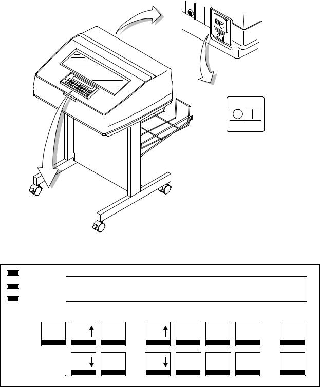
(Off) (On)
Power Switch
Power
LCD
Ready
Processing
Menu |
|
|
Printer Con- |
Attention |
||
|
|
figuration |
|
|
|
|
|
|
Scroll |
Scroll |
Enter |
Return |
Micro |
Micro
Line |
Feed |
View |
Form |
Start |
Cancel |
Feed |
Set Top |
Stop |
Eject/ |
|
Of Form |
Restore |
||
|
Figure 3. Electrical Controls and Indicators, Pedestal Model
Maintenance Overview |
23 |
Mechanical Controls and Indicators, All Models (Figure 4)
Control or |
|
|
|
Function |
|
|
|
|
|
|
|
|
||||||||||
Indicator |
|
|
|
|
|
|
|
|
|
|
|
|||||||||||
|
|
|
|
|
|
|
|
|
|
|
|
|
|
|
|
|
|
|
|
|
||
|
|
|
|
|
|
|
|
|
|
|
|
|
|
|
|
|
|
|
|
|
|
|
Forms Thickness |
Sets the platen for paper and forms of different |
|||||||||||||||||||||
Lever |
thicknesses. Lever must be fully opened (raised) to load |
|||||||||||||||||||||
or unload paper. |
|
|
|
|
|
|
|
|
|
|
|
|
||||||||||
|
|
|
|
|
|
|
|
|
|
|
|
|
||||||||||
Paper Supports |
Help prevent paper jams by supporting inner sections of |
|||||||||||||||||||||
|
paper. Positioned manually by sliding them along shafts. |
|||||||||||||||||||||
Forms Thickness |
Indicates relative thickness of forms/paper. Set this lever |
|||||||||||||||||||||
Pointer and Scale |
at A for thin (single-part) forms, B for thicker forms, and |
|||||||||||||||||||||
|
so on. |
|
|
|
|
|
|
|
|
|
|
|
|
|||||||||
Tractors (2) |
Hold and feed paper. Used to set side margin and |
|||||||||||||||||||||
|
position paper horizontally. |
|
|
|
|
|
|
|
|
|
|
|
|
|||||||||
Tractor locks (2) |
Lock tractors in position. |
|
|
|
|
|
|
|
|
|
|
|
|
|||||||||
Horizontal |
Allows fine positioning of left print margin. Moves paper |
|||||||||||||||||||||
Adjustment Knob |
and tractors left or right. |
|
|
|
|
|
|
|
|
|
|
|
|
|||||||||
Vertical Position |
Used to set top of form or first line to be printed. Rotate |
|||||||||||||||||||||
Knob |
to move paper vertically. Works when Forms Thickness |
|||||||||||||||||||||
Lever is open. |
|
|
|
|
|
|
|
|
|
|
|
|
||||||||||
|
|
|
|
|
|
|
|
|
|
|
|
|
||||||||||
Ribbon Loading |
Instructions showing how to load the ribbon correctly. |
|||||||||||||||||||||
Path Diagrams |
One diagram is cast in relief on the shuttle cover, and |
|||||||||||||||||||||
another is printed on the paper scale. |
||||||||||||||||||||||
|
||||||||||||||||||||||
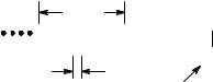
Paper Scale |
A horizontal scale graduated in tenths of an inch, useful |
|||||||||||||||||||||
|
for setting paper margins and counting text columns. |
|||||||||||||||||||||
|
(See below.) |
|
|
|
|
|
|
|
|
|
|
|
|
|||||||||
|
|
|
|
|
1 inch |
|
|
|
|
|
|
|
|
|
|
|
|
|||||
|
|
|
|
|
|
|
|
|
|
|
|
|
|
|
|
|
|
|
|
|
|
|
|
|
|
|
|
|
|
|
|
|
|
|
|
|
|
|
|
|
|
|
|
|
|
|
|
|
|
|
|
|
|
|
|
|
|
|
|
|
|
|
|
|
|
|
|
|
|
1 |
|
|
|
|
|
|
10 |
|
20 |
||||||||||||
|
|
|
|
0.1 inch |
|
|
|
|
Column |
|||||||||||||
|
|
|
|
|
|
|
|
|
|
|
|
|
|
Number |
||||||||
|
|
|
|
|
|
|
|
|
|
|
|
|
|
|
|
|
|
|
|
|
|
|
24 |
Maintenance Overview |

Left Tractor
Horizontal
Adjustment
Knob
Tractor Lock
Ribbon Loading Path
Diagrams
Paper Scale
Paper
Supports
Right Tractor
Tractor Vertical
Lock Position
Knob
Forms Thickness
Lever and Scale
Forms
Thickness
Pointer
Figure 4. Mechanical Controls and Indicators
Maintenance Overview |
25 |

Tools, Test Equipment, and Supplies
The tools and equipment required for field level maintenance of the printer are listed below.
Item |
Part No. |
|
|
6400 Line Matrix Printer Configuration |
|
Utility Disk |
63H7379 |
1±30 Inch-pound Torque Screwdriver |
16F1661 |
ESD Wrist Strap |
6405959 |
Feeler Gauge, .010 inch |
|
Feeler Gauge, .011 inch |
|
Feeler Gauge, .040 inch |
|
Force Gauge, 20 lb |
25F9687 |
Grip Ring Pliers |
9900317 |
Lubricant, Bearing, IBM #20 |
117397 |
DIP Module Extracting Tool |
9900764 |
Nut Driver, 1/4 inch |
|
Nut Driver, 5/16 inch |
|
Open End Wrench, 7/32 inch |
1650843 |
Open End Wrench, 5/16 inch |
9900005 |
PLCC Module Pick Extraction Tool |
73G5523 |
PLCC Module Plier Extraction Tool |
10G3902 |
Screwdriver, Philips, #1 |
73G5362 |
Screwdriver, Philips, #2 |
73G5363 |
Spring Hook, Heavy Duty |
|
Tie Wraps |
75X5972 |
Torque Screwdriver Adapter |
39F8449 |
Torque Screwdriver Hex Adapter 3/32 inch |
39F8451 |
Torque Screwdriver Hex Adapter 5/32 inch |
39F8450 |
Torque Screwdriver Hex Adapter 3/16 inch |
39F8455 |
Torque Screwdriver Hex Adapter 5/64 inch |
16F1663 |
Torx** T-10 Bit |
83F2834 |
|
|
26 |
Maintenance Overview |

2 Installation
Installation and configuration of the printer are covered in the
6400 Line Matrix Printer Set-Up Guide, Form No. S544±5640
Installation, operation, and replacement parts for the optional coax/twinax interface are covered in the Coax/Twinax Multi±Platform Interface Option Installation and Operation Guide, Form No. S246±0149.
Installation, configuration, and troubleshooting of the Network Print Server are covered in the following documents:
♦IBM Network Print Server Ethernet Administrator's Guide, Form No. S246±0111
♦IBM Network Print Server Token-Ring Administrator's Guide, Form No. S246±0112
♦The Network Print Server Technical Reference Manual is included on a diskette that comes with the Network Print Server. This ªsoftcopyº document is in Adobe Acrobat Reader format.
Installation |
27 |
28 |
Installation |
3 Preventive Maintenance
Cleaning the Printer
Aside from normal replenishment of paper and ribbons, the only preventive maintenance required for the printer is periodic cleaning.
Because operating conditions vary widely, the user must determine how often to clean the printer.
There is no guarantee that the user will clean the printer regularly, however, so you should clean the printer whenever you are called to service it.
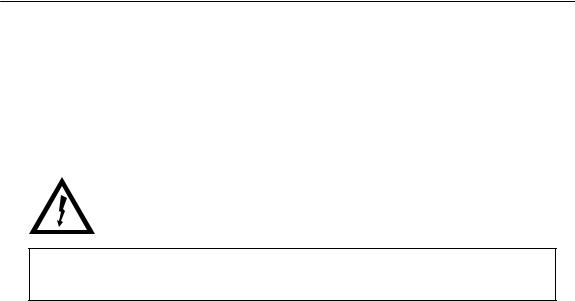
DANGER:
<2> Switch off printer power and unplug the printer power cord before cleaning the printer.
ATTENTION
Do not use abrasive cleaners, particularly on the window.
Do not drip water into the printer. Damage to the equipment will result. Do not spray directly onto the printer when using spray solutions (spray the cloth, then apply the dampened cloth to the printer).
Do not vacuum circuit boards.
Preventive Maintenance |
29 |
Cleaning the Exterior
1.Power off the printer.
2.Disconnect the AC power cord from the power source.
3.Wipe the outside of the enclosure with a clean, lint-free cloth dampened (not wet) with water and a mild detergent or window cleaning solution.
4.Dry the enclosure with a clean, lint-free cloth.
5.Clean the inside of the printer, as described below.
Cleaning the Interior
1.Power off the printer.
2.Disconnect the AC power cord from the power source.
3.Open the printer cover.
4.Remove paper from the printer.
5.Remove the ribbon.
6.Using a soft-bristled, non-metallic brush, wipe paper dust and ribbon lint off the tractors, shuttle cover assembly, base casting, and ribbon guides. Vacuum up the residue.
7.Wipe the splined shaft and the ribbon guides with a soft cloth.
8.Vacuum up dust or residue that has accumulated inside the lower cabinet.
9.Wipe the interior of the lower cabinet with a clean, lint-free cloth dampened with water and a mild detergent or window cleaning solution.
10.Dry the cabinet interior with a clean, lint-free cloth.
11.Clean the shuttle frame assembly, as described below.
30 |
Preventive Maintenance |
Loading...