


 Loading...
IBM 4QX, 42X, 200, 42E, 900 User Manual
...
Hardware Maintenance Manual
IBM
IBM PC Server/Enterprise Racks
Hardware Maintenance Manual
IBM
IBM PC Server/Enterprise Racks

Note:
Before using this information and the product it supports, be sure to read the general information under “Notices” on page 195.
Sixth Edition (November 1999) Updated April 2001
The following paragraph does not apply to the United Kingdom or any country where such provisions are inconsistent with local law:
INTERNATIONAL BUSINESS MACHINES CORPORATION PROVIDES THIS PUBLICATION "AS IS" WITHOUT WARRANTY OF ANY KIND, EITHER EXPRESS OR IMPLIED, INCLUDING, BUT NOT LIMITED TO, THE IMPLIED WARRANTIES OF MERCHANTABILITY OR FITNESS FOR A PARTICULAR PURPOSE. Some states do not allow disclaimer of express or implied warranties in certain transactions, therefore, this statement may not apply to you.
This publication could include technical inaccuracies or typographical errors. Changes are periodically made to the information herein; these changes will be incorporated in new editions of the publication. IBM may make improvements and/or changes in the product(s) and/or the program(s) described in this publication at any time.
This publication was developed for products and services offered in the United States of America. IBM may not offer the products, services, or features discussed in this document in other countries, and the information is subject to change without notice. Consult your local IBM representative for information on the products, services, and features available in your area.
Requests for technical information about IBM products should be made to your IBM reseller or IBM marketing representative.
© Copyright International Business Machines Corporation 2001. All rights reserved.
US Government Users Restricted Rights – Use, duplication or disclosure restricted by GSA ADP Schedule Contract with IBM Corp.

About this supplement
This supplement contains diagnostic and service information for the IBM PC Server Rack Enclosure and the IBM Rack enclosures:
IBM PC Server Rack Enclosure models:
•Type 9306 19-inch and 24-inch Models:
—4QS, 4QX, 9QS
—9QX, 9TS, 9TX
•IBM Rack enclosure models:
—Type 9306 Models 200, 900
—Type 9308 Models 42P, 42X, 42S, 42E, 4SA, 4SB (NetBAY42 Enterprise)
•IBM NetBAY3 enclosure
•IBM NetBAY3E enclosure
This supplement should be used with the related service information in the IBM PC Servers Hardware Maintenance Manual (part number 70H0751, form number S30H- 2501-01).
Important: This manual is intended for trained servicers who are familiar with IBM PC Server and IBM Server products.
Before servicing an IBM product, be sure to review “Safety information” on page 183.
Related publications
The following publications are available for IBM products. For more information, contact IBM or an IBM Authorized Dealer.
© Copyright IBM Corp. 2001 |
iii |
For information about |
See publication |
|
|
PC Servers |
IBM PC Servers Hardware Maintenance Manual |
|
(S30H-2501) |
|
|
PS/2 Computers |
IBM Personal System/2 Hardware Maintenance |
|
Manual (S52G-9971) |
|
|
PS/ValuePoint Computers |
IBM PS/ValuePoint Hardware Maintenance Service |
|
and Reference (S61G-1423) |
|
|
Laptop, Notebook, Portable, and |
IBM Mobile Systems Hardware Maintenance |
ThinkPad Computers (L40, CL57, N45, |
Manual Volume 1 (S82G-1501) |
N51, P70/P75, ThinkPad 300, 350, 500, |
|
510, 710T, Expansion Unit, Dock I, |
|
Dock II) |
|
|
|
ThinkPad Computers (ThinkPad 340, |
IBM Mobile Systems Hardware Maintenance |
355, 360, 370, 700, 701, 720, 750, 755) |
Manual Volume 2 (S82G-1502) |
|
|
ThinkPad Computers (ThinkPad 365, |
IBM Mobile Systems Hardware Maintenance |
760) |
Manual Volume 3 (S82G-1503) |
|
|
Monitors (Displays) (February 1993) |
IBM PS/2 Display HMM Volume 1 (SA38-0053) |
|
|
Monitors (December 1993) |
IBM Color Monitor HMM Volume 2 (S71G-4197) |
|
|
IBM Monitors (P Series) (February |
IBM Monitor HMM Volume 3 (S52H-3679) |
1996) |
|
|
|
IBM 2248 Monitor (February 1996) |
IBM Monitor HMM Volume 4 (S52H-3739) |
|
|
Disk Array technology overview and |
Configuring Your Disk Array booklet (S82G-1506) |
using the IBM RAID Configuration |
|
Program |
|
|
|
Installation Planning for Personal |
Personal System/2 Installation Planning and |
System/2 computers |
Beyond (G41G-2927) |
|
|
Installation Planning for Advanced |
Advanced PS/2 Servers Planning and Selection |
Personal System/2 Servers |
Guide (GG24-3927) |
|
|
iv Hardware Maintenance Manual: IBM PC Server/Enterprise Racks

Contents
About this supplement . . . . . . . . . . . . . . . iii
Related publications . . . . . . . . . . . . . . . . . . . . . . . . . . . . . . iii
IBM PC Server/Enterprise rack enclosures 1
General checkout. . . . . . . . . . . . . . . . . . . . . . . . . . . . . . . . . 1 Power checkout . . . . . . . . . . . . . . . . . . . . . . . . . . . . . . . . . . 2 Powering off the rack . . . . . . . . . . . . . . . . . . . . . . . . . . . . . 3
Type 9306 Models 4QS, 4QX, 9QS, 9QX, 9TS, 9TX . . . . . . . . . . . . . . . . . . . . . . . . . . . 5
Features. . . . . . . . . . . . . . . . . . . . . . . . . . . . . . . . . . . . . . . . . 5 IBM PC Server expansion rack models. . . . . . . . . . . . 5 Locations. . . . . . . . . . . . . . . . . . . . . . . . . . . . . . . . . . . . . . . . 5 Server selector console . . . . . . . . . . . . . . . . . . . . . . . . . 6 Server selector unit . . . . . . . . . . . . . . . . . . . . . . . . . . . . 6 Connections . . . . . . . . . . . . . . . . . . . . . . . . . . . . . . . . . . 7 Power distribution unit. . . . . . . . . . . . . . . . . . . . . . . . . 7 Cooling fan . . . . . . . . . . . . . . . . . . . . . . . . . . . . . . . . . . . 8 Sliding trays . . . . . . . . . . . . . . . . . . . . . . . . . . . . . . . . . . 9 Sliding rails . . . . . . . . . . . . . . . . . . . . . . . . . . . . . . . . . . 10 Keyboard tray. . . . . . . . . . . . . . . . . . . . . . . . . . . . . . . . 11
Parts listing (Type 9306 – 19-inch) Models 9QS, 9TS and 9QX, 9TX. . . . . . . . . . . . . . . . . . . . . . . . . . . . . . . . . . . . . . . 12 Parts listing (Type 9306 – 24-inch) Models 4QS, 4QX . 17
Type 9306 Model 200 . . . . . . . . . . . . . . . . . 21
Features. . . . . . . . . . . . . . . . . . . . . . . . . . . . . . . . . . . . . . . . 21 Locations. . . . . . . . . . . . . . . . . . . . . . . . . . . . . . . . . . . . . . . 21 Side panel . . . . . . . . . . . . . . . . . . . . . . . . . . . . . . . . . . . 21 Selector switch locations . . . . . . . . . . . . . . . . . . . . . . . 22 Power Distribution Unit . . . . . . . . . . . . . . . . . . . . . . . 26 Blank bezel . . . . . . . . . . . . . . . . . . . . . . . . . . . . . . . . . . 27 Fixed shelf . . . . . . . . . . . . . . . . . . . . . . . . . . . . . . . . . . . 27 Keyboard tray. . . . . . . . . . . . . . . . . . . . . . . . . . . . . . . . 28 Installing a flat panel monitor rack mount kit. . . . . 29 Removing the existing flat panel monitor stand . . . 29 Installing the new monitor stand. . . . . . . . . . . . . . . . 31 Starting the system. . . . . . . . . . . . . . . . . . . . . . . . . . . . 35 Configuring the selector switch . . . . . . . . . . . . . . . . . 35 Switching among servers . . . . . . . . . . . . . . . . . . . . . . 36 Advanced selector switch functions . . . . . . . . . . . . . 37 Resetting the selector switch . . . . . . . . . . . . . . . . . . . 45 Making connections under power. . . . . . . . . . . . . . . 46 Parts Listing (Type 9306 Model 200). . . . . . . . . . . . . . . . 47
Type 9306 Model 900/910 . . . . . . . . . . . . . 51
Features. . . . . . . . . . . . . . . . . . . . . . . . . . . . . . . . . . . . . . . . 51 Locations . . . . . . . . . . . . . . . . . . . . . . . . . . . . . . . . . . . . 51 Parts listing (Type 9306 Model 900/910) . . . . . . . . . . . . 77
NetBAY 42 Enterprise Rack (Type 9308 Models 42P, 42X, 4SA, 4SB, 42S, 42E) . . 81
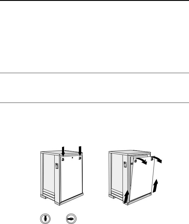
Features. . . . . . . . . . . . . . . . . . . . . . . . . . . . . . . . . . . . . . . . 81 Locations. . . . . . . . . . . . . . . . . . . . . . . . . . . . . . . . . . . . . . . 85 Removing and installing panels . . . . . . . . . . . . . . . . 85 Doors . . . . . . . . . . . . . . . . . . . . . . . . . . . . . . . . . . . . . . . 87 Removing and installing the top 6U portion of the rack
91
Installing the stabilizer bracket . . . . . . . . . . . . . . . . . 92
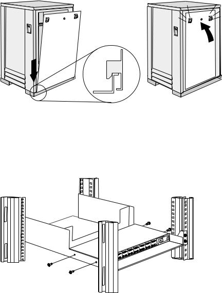
Attaching rack cabinets in a suite . . . . . . . . . . . . . . . 92 Installing L-channel support rails to rack mounting
brackets . . . . . . . . . . . . . . . . . . . . . . . . . . . . . . . . . . . . . . . . 94 Installing a server . . . . . . . . . . . . . . . . . . . . . . . . . . . . 97 Fixed shelf . . . . . . . . . . . . . . . . . . . . . . . . . . . . . . . . . . 100 Keyboard tray . . . . . . . . . . . . . . . . . . . . . . . . . . . . . . . 101 Monitor shelf. . . . . . . . . . . . . . . . . . . . . . . . . . . . . . . . 102 Installing a flat panel monitor rack mount kit . . . . 103 Removing the existing flat panel monitor stand . . 103 Installing the new monitor stand. . . . . . . . . . . . . . . 105 Blank filler panel . . . . . . . . . . . . . . . . . . . . . . . . . . . . 109
Parts listing (Type 9308 Model 42P, 42X) . . . . . . . . . . . 111
NetBAY3 enclosure . . . . . . . . . . . . . . . . . 115
Features . . . . . . . . . . . . . . . . . . . . . . . . . . . . . . . . . . . . . . . 115 Locations. . . . . . . . . . . . . . . . . . . . . . . . . . . . . . . . . . . . . . 115 Casters . . . . . . . . . . . . . . . . . . . . . . . . . . . . . . . . . . . . . 116 Foot pads . . . . . . . . . . . . . . . . . . . . . . . . . . . . . . . . . . . 116 Front cover . . . . . . . . . . . . . . . . . . . . . . . . . . . . . . . . . 117 Rear panel . . . . . . . . . . . . . . . . . . . . . . . . . . . . . . . . . . 117 Device side rails . . . . . . . . . . . . . . . . . . . . . . . . . . . . . 118 Stacking NetBAY3 enclosures. . . . . . . . . . . . . . . . . . 118 Parts Listing (NetBAY3) . . . . . . . . . . . . . . . . . . . . . . . . . 121
NetBAY3E enclosure . . . . . . . . . . . . . . . . 123
Features . . . . . . . . . . . . . . . . . . . . . . . . . . . . . . . . . . . . . . . 123 Locations. . . . . . . . . . . . . . . . . . . . . . . . . . . . . . . . . . . . . . 123 Casters . . . . . . . . . . . . . . . . . . . . . . . . . . . . . . . . . . . . . 124 Front cover . . . . . . . . . . . . . . . . . . . . . . . . . . . . . . . . . 124 Rear panel . . . . . . . . . . . . . . . . . . . . . . . . . . . . . . . . . . 125 Device side rails . . . . . . . . . . . . . . . . . . . . . . . . . . . . . 126 Stacking NetBAY3E enclosures . . . . . . . . . . . . . . . . 126 Parts listing (NetBAY3E). . . . . . . . . . . . . . . . . . . . . . . . . 127
IBM NetBAY console switch . . . . . . . . . . 129
Features . . . . . . . . . . . . . . . . . . . . . . . . . . . . . . . . . . . . . . . 130
Tool requirements . . . . . . . . . . . . . . . . . . . . . . . . . . . . . . 131 Specifications . . . . . . . . . . . . . . . . . . . . . . . . . . . . . . . . . . 132 Installation overview . . . . . . . . . . . . . . . . . . . . . . . . . . . 132 Installing a console switch in a monitor shelf . . . . 132 Installing a console switch vertically in a rack. . . . 134 Installing a console switch horizontally in a rack . 137 Parts listing (NetBAY Console Switch). . . . . . . . . . . . . 139
NetBAY Power Distribution Units . . . . . . 141
NetBAY rack Power Distribution Unit introduction . 141 Tool requirements. . . . . . . . . . . . . . . . . . . . . . . . . . . . 142 Installation overview . . . . . . . . . . . . . . . . . . . . . . . . . 142 Installing devices vertically . . . . . . . . . . . . . . . . . . . 142 Installing a single device horizontally . . . . . . . . . . 144 Installing two devices horizontally . . . . . . . . . . . . . 146 Cabling your PDUs . . . . . . . . . . . . . . . . . . . . . . . . . . 148
NetBAY front-end Power Distribution Unit introduction . 156
Tool requirements. . . . . . . . . . . . . . . . . . . . . . . . . . . . 157 Installation overview . . . . . . . . . . . . . . . . . . . . . . . . . 157 Installing a single device vertically . . . . . . . . . . . . . 157 Installing two devices vertically . . . . . . . . . . . . . . . 160 Rack PDU specifications . . . . . . . . . . . . . . . . . . . . . . 164
© Copyright IBM Corp. 2001 |
v |
Line cords . . . . . . . . . . . . . . . . . . . . . . . . . . . . . . . . . . 165 Power cables . . . . . . . . . . . . . . . . . . . . . . . . . . . . . . . . 165
NetBAY server dual-cord Power Distribution Unit introduction . . . . . . . . . . . . . . . . . . . . . . . . . . . . . . . . . . . 166
Tool requirements . . . . . . . . . . . . . . . . . . . . . . . . . . . 167 Installation overview. . . . . . . . . . . . . . . . . . . . . . . . . 167 Installing devices vertically . . . . . . . . . . . . . . . . . . . 167 Installing a single device horizontally . . . . . . . . . . 169 Installing two devices horizontally . . . . . . . . . . . . . 171 Cabling your PDUs . . . . . . . . . . . . . . . . . . . . . . . . . . 173 Power cables . . . . . . . . . . . . . . . . . . . . . . . . . . . . . . . . 180 Line cords . . . . . . . . . . . . . . . . . . . . . . . . . . . . . . . . . . 181
Parts listing (Power Distribution Units) . . . . . . . . . . . 181
Related service information . . . . . . . . . . 183
Safety information . . . . . . . . . . . . . . . . . . . . . . . . . . . . . . 183 Safety notice (multi-lingual translations) . . . . . . . . 191 Safety inspection guide . . . . . . . . . . . . . . . . . . . . . . . 192 Handling electrostatic discharge-sensitive devices 193 Grounding requirements. . . . . . . . . . . . . . . . . . . . . . 194
Problem determination tips . . . . . . . . . . . . . . . . . . . . . . 194 Notices. . . . . . . . . . . . . . . . . . . . . . . . . . . . . . . . . . . . . . . . 195 Send us your comments! . . . . . . . . . . . . . . . . . . . . . . . . 196 Trademarks . . . . . . . . . . . . . . . . . . . . . . . . . . . . . . . . . . . . 197
vi Hardware Maintenance Manual: IBM PC Server/Enterprise Racks

IBM PC Server/Enterprise rack enclosures
General checkout. . . . . . . . . . . . . . . . . . . . . . . . . . . . . |
1 |
Powering off the rack. . . . . . . . . . . . . . . . . . . . . . . . . |
3 |
Power checkout . . . . . . . . . . . . . . . . . . . . . . . . . . . . . . |
2 |
|
|
General checkout
Use the following procedure for diagnosing keyboard, mouse, and video problems for the IBM PC Server Rack Enclosure and the IBM Rack enclosures (Type 9306 and Type 9308).
For power problems, see “Power checkout” on page 2.
Attention:
•For Models 4QS, 4QX, 9QS, 9QX, 9TS, 9TX only:
Ensure that the voltage selector switch on each server installed in the server rack is set to 230 V ac.
•For Models 200, 900 only:
Ensure that the voltage selector switch on each server installed in the server rack is set to the proper voltage as supplied by the Power Distribution Unit, PDU.
1.Check the following:
•Ensure the external power cord is in good condition and properly connected to a known-good power source.
•Ensure the internal power cables are in good condition and properly connected. (The internal power cables connect between the power distribution unit and the servers installed in the server rack.)
•Ensure the following devices are powered on.
a.Power distribution unit
b.Server selector unit
c.All system units
d.Display
2.If the items/conditions specified in step 1. are not okay, correct the problem and verify that the server rack is operating correctly.
3.If the items/conditions specified in step 1. are okay, then, using the server selector keypad buttons, check the operation of the failing device for all of the servers that are installed in the rack.
4.Did the failure occur on more than one server?
•NO: Go to the Hardware Maintenance manual for the server that was selected when the failure occurred. Disconnect the keyboard and mouse from the server selector unit and connect them directly to the failing server. Then, run the server diagnostic programs on the failing server.
If the problem still remains, disconnect the keyboard and mouse from the failing server and reconnect them to the server selector unit. Then, replace the server rack components in the following order until the problem goes away.
a.Device cable (connects between the server selector unit and the server that was selected when the failure occurred).
© Copyright IBM Corp. 2001 |
1 |

b.Server selector cable (connects between the server selector keypad and the server selector unit).
c.Server selector keypad.
d.Server selector unit.
•YES: Power-off the server rack and replace the server rack components in the following order until the problem goes away. See “Powering off the rack” on page 3.
a.Device extender cable (connects between the device and the server selector unit)
b.Failing device
c.Server selector cable (connects between the server selector keypad and the server selector unit)
d.Server selector keypad
e.Server selector unit
Power checkout
Use the following procedure for diagnosing power problems for the IBM PC Server Rack Enclosure and IBM Rack enclosure (Type 9306).
Attention:
•For Models 4QS, 4QX, 9QS, 9QX, 9TS, 9TX only:
Ensure that the voltage selector switch on each server installed in the server rack is set to 230 V ac.
•For Models 200, 900 only:
Ensure that the voltage selector switch on each server installed in the server rack is set to the proper voltage as supplied by the Power Distribution Unit, PDU.
1.Check the following:
•Ensure the external power cord is in good condition and properly connected to a known-good power source.
•Ensure the internal power cables are in good condition and properly connected. (The internal power cables connect between the power distribution unit and the servers installed in the server rack.)
•Ensure the following devices are powered on.
a.Power distribution unit
b.Server selector unit
c.All system units
d.Display
2.If the items/conditions in step 1. are not okay, correct the problem and verify correct operation of the server rack.
3.If the items/conditions specified in step 1. are okay, then, using the server selector keypad buttons, check for correct operation of all the servers installed in the rack.
4.Did the failure occur on more than one server?
•No: Go to the Hardware Maintenance manual for the server that was selected when the failure occurred and run the server diagnostic programs. If the problem still remains, replace the power distribution unit.
2 Hardware Maintenance Manual: IBM PC Server/Enterprise Racks
•Yes: Power-off the server rack and replace the server rack components in the following order until the problem goes away. See “Powering off the rack” on page 3.
a.Power distribution unit fuse.
b.Power distribution unit.
Powering off the rack
Before performing service on the rack, follow this procedure to prevent personal injury and to avoid damaging the rack and the installed servers.
To power-off the IBM PC Server Rack:
1.Shut down and power-off all installed servers.
2.Power-off the server selector unit.
3.If a UPS system is installed in the rack, power-off the UPS system.
4.Disconnect power from the IBM PC Server Rack.
•If the rack is plugged into a wall-mounted power supply, disconnect the power cord plug from the wall socket.
•If the power cord is wired directly into the installed location's power supply, open the rear door of the rack cabinet and disconnect the power plug from the base of the power distribution unit.
IBM PC Server/Enterprise rack enclosures 3
4 Hardware Maintenance Manual: IBM PC Server/Enterprise Racks

Type 9306 Models 4QS, 4QX, 9QS, 9QX, 9TS, 9TX
Features. . . . . . . . . . . . . . . . . . . . . . . . . . . . . . . . . . . . . 5 IBM PC Server expansion rack models . . . . . . . . . . 5 Locations. . . . . . . . . . . . . . . . . . . . . . . . . . . . . . . . . . . . 5 Server selector console . . . . . . . . . . . . . . . . . . . . . . . . 6 Server selector unit . . . . . . . . . . . . . . . . . . . . . . . . . . . 6 Connections . . . . . . . . . . . . . . . . . . . . . . . . . . . . . . . . . 7 Power distribution unit . . . . . . . . . . . . . . . . . . . . . . . 7 Cooling fan . . . . . . . . . . . . . . . . . . . . . . . . . . . . . . . . . . 8 Sliding trays . . . . . . . . . . . . . . . . . . . . . . . . . . . . . . . . . 9
Single latch rail tray . . . . . . . . . . . . . . . . . . . . . . . . . . 9 Dual latch rail tray . . . . . . . . . . . . . . . . . . . . . . . . . . 10 Sliding rails . . . . . . . . . . . . . . . . . . . . . . . . . . . . . . . . 10 Keyboard tray . . . . . . . . . . . . . . . . . . . . . . . . . . . . . . .11 Parts listing (Type 9306 – 19-inch) Models 9QS, 9TS and 9QX, 9TX . . . . . . . . . . . . . . . . . . . . . . . . . . . . . . 12 Parts listing (Type 9306 – 24-inch) Models 4QS, 4QX 17
Features
The 9306 IBM PC Server Rack Enclosure, models 4QS, 9QS, 9TS come in three primary models.
•19-inch Quad Primary Server Rack, Model 9QS
•19-inch Tri Primary Server Rack, Model 9TS
•24-inch Quad Primary Server Rack, Model 4QS
A Quad Primary Server Rack can house up to four IBM PC Servers. The Tri Primary Server Rack can house up to three IBM PC Servers.
Both Quad and Tri Primary Server Racks provide a built in server selector which connects to one set of console devices (monitor, keyboard, and mouse.) The server selector works independently from the server's operating systems, enabling the connected servers to run different operating systems.
These IBM 9306 PC Server Rack Enclosure models are shipped preassembled and precabled.
IBM PC Server expansion rack models
Three optional IBM PC Server Rack Expansion models are available to expand the capacity of the IBM PC Server Rack Primary Enclosure. The optional IBM PC Server Rack Expansion models are:
•19-inch Quad Expansion Rack, Model 9QX
•19-inch Tri Expansion Rack, Model 9TX
•24-inch Quad Expansion Rack, Model 4QX
The IBM PC Server Rack Expansion models allow the installation of up to four more servers using the Primary IBM PC Server Rack monitor, keyboard, and mouse.
Locations
The following sections contain information on specific equipment locations.
Note: For instructions on how to power-off the rack, see “Powering off the rack” on page 3.
© Copyright IBM Corp. 2001 |
5 |
Server selector console
To remove the Server Selector Console:
1.Power-off the rack.
2.Use an 1/8-inch allen wrench to remove screws.
3.Disconnect the server selector cable from the back of the server selector console.
4.Remove the server selector console from the cabinet.
|
Server |
|
Monitor |
Selector |
|
Console |
||
Bezel |
||
|
Server |
Server |
Server |
|
Selector |
|||
Selector |
|||
Selector |
|||
Keypad |
|||
Electronics |
|||
Cable |
|||
|
|||
|
|
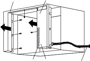
Server selector unit
The server selector unit is located in the upper rear of the rack cabinet. The server selector unit can only be accessed or removed from the rear of the IBM Rack cabinet.
CAUTION:
The server selector unit is heavy. You will need two people to safely remove the server selector unit. See “Safety notice (multi-lingual translations)” on page 191.
To remove the server selector unit:
1.Power-off the rack.
2.Unplug the keyboard, mouse, video cables, and the power cord.
3.Remove the server selector console.
4.With one person bracing the server selector unit from below, have the second person use a 5/16-inch wrench to remove the four nuts that secure the server selector unit to the rack cabinet.
5.Remove the server selector unit from the cabinet.
Note: When replacing the server selector unit, be sure that the Server Selector cable is fed through the indentation along the left side of the server selector unit.
6 Hardware Maintenance Manual: IBM PC Server/Enterprise Racks
Server |
|
|
|
|
Server |
||
|
|
|
|
Selector |
|||
Selector |
|
|
|
|
|||
|
|
|
|
Unit |
|||
Cable |
|
|
|
|
|||
|
|
|
|
|
|
|
|
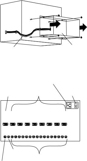
Connections |
|
|
|
|
|
|
|
|
AC Power |
|
|
|
|
|
|
|
Input |
|
|
|
|
|
|
Server Rack |
Server |
Server Selector |
|||||
Monitor |
Monitor |
Unit On-Off |
|||||
Connection |
Connections |
Switch |
|||||
|
|
|
|
|
|
|
|
|
|
|
|
|
|
|
|
|
|
|
|
|
|
|
|
|
|
|
|
|
|
|
|
|
|
|
|
|
|
|
|
|
|
|
|
|
|
|
|
|
|
|
|
|
|
|
|
|
|
|
|
|
|
|
|
M |
V |
V |
V |
V |
V |
V |
V |
V |
O |
G |
G |
G |
G |
G |
G |
G |
G |
N |
A |
A |
A |
A |
A |
A |
A |
A |
O |
1 |
2 |
3 |
4 |
5 |
6 |
7 |
8 |
K M
B O K M K M K M K M K M K M K M K M
O U 1 1 2 2 3 3 4 4 5 5 6 6 7 7 8 8
Server Rack |
|
|
Mouse |
Server Keyboard |
|
Connection |
||
and Mouse |
||
|
||
Server Rack |
Connections |
|
Keyboard |
|
|
Connection |
|
Power distribution unit
Note: For information and installation instructions for the IBM NetBAY Rack Power Distribution Units, see “NetBAY Power Distribution Units” on page 141".
Note: To remove the power distribution unit, you might need to remove the right side cabinet panel, the server installed in sliding tray 2 (in the primary IBM PC Server Rack), or sliding tray 5 (in the IBM PC Server Expansion Rack).
To remove the power distribution unit:
1.Power-off the rack.
2.Disconnect all power plugs from the power distribution unit.
3.Using a Phillips screwdriver, remove the four screws from the front of the power distribution unit.
Type 9306 Models 4QS, 4QX, 9QS, 9QX, 9TS, 9TX 7
Note: These screws are held in place by nuts and washers. Hold the nut while you are unscrewing the screw to prevent the nut and washer from falling into the bottom of the cabinet.
4.Remove the power distribution unit from the cabinet.
|
AC Power |
|
|
Input |
|
AC Fuse |
|
|
Circuit |
|
|
Breaker |
|
|
115V AC |
AC Power |
|
Output |
||
Power-On |
||
|
||
Indicator |
|
|
Voltage |
|
|
Selection |
|
|
Switch |
|
|
230V AC |
|
|
Power-On |
|
|
Indicator |
|
Cooling fan
To remove the cooling fan:
1.Power-off the rack.
2.Open the rear door of the rack cabinet.
3.Disconnect the power plug from the rear of the cooling fan.
4.Use a 5/16-inch wrench to remove the eight nuts that secure the cooling fan to the top of the rack cabinet.
5.Remove the cooling fan from the cabinet.
Note: When installing the fan, make sure that the green and yellow ground wire is attached to one of the top fan mounting screws and that the strain-relieving clamp is attached to another. The power cable should be secured by the strainrelieving clamp.
8 Hardware Maintenance Manual: IBM PC Server/Enterprise Racks
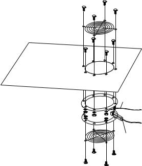
Ground
Wire
Power
Plug
Sliding trays
Models 4QS and 4QX come with either single latch slide rails or dual latch slide rails. Single latch slide rails have a front latch release on the right rail only. Dual latch slide rails have a front latch release on both rails. The slide rail FRU number for the 24-inch rack replaces the single latch slide rail with the dual latch slide rail.
Note: If a server is installed on a tray being removed, first remove the server.
Single latch rail tray
To remove a sliding tray with single latch rails:
1.Power-off the rack.
2.Open the rear door of the rack cabinet and remove the pin 1 that secures the sliding tray to the cable management arm
3.Loosen the thumbscrews 2 on the sliding tray and fully extend the sliding tray.
4.Use a 3/32-inch allen wrench to remove the five screws 3 from the left side of the sliding tray.
5.Lift the rear locking tab 4 and push the sliding tray approximately two inches into the cabinet.
6.Release the forward locking tab 5. Then, while holding the sliding tray in place, use your other hand to grasp the outside sliding rail 6 and push it into the rack cabinet until it disconnects from the sliding tray.
Type 9306 Models 4QS, 4QX, 9QS, 9QX, 9TS, 9TX 9
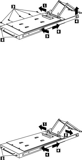
Dual latch rail tray
To remove a sliding tray with dual latch rails:
1.Power-off the rack.
2.Open the rear door of the rack cabinet and remove the pin 1 that secures the sliding tray to the cable management arm.
3.Loosen the thumbscrews 2 on the sliding tray and fully extend the sliding tray.
4.Push in on the spring of the right rear locking tab 3 and push the sliding tray approximately two inches into the cabinet.
5.Release both left and right forward locking tabs 4. Then, while holding the sliding tray in place, push both left and right outside sliding rails 5 into the rack cabinet until it disconnects from the sliding tray.
Note: Left side view for 4 and 5 are not shown.
Sliding rails
This procedure is for single latch sliding rails and dual latch sliding rails.
For single latch sliding rails, the right rail is the one that has the front latch. The left rail does not have a front latch.
For dual latch sliding rails, the right rail is the one that has the rear latch. The left rail does not have a rear latch.
To remove the sliding rails:
1.Power-off the rack.
2.Remove the sliding tray that is attached to the sliding rails that you want to remove. See “Sliding trays” on page 9.
3.Use a 3/32-inch allen wrench to remove the four screws that secure each of the sliding rails to the rack cabinet.
10 Hardware Maintenance Manual: IBM PC Server/Enterprise Racks
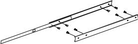
Note: You will need to adjust the position of the sliding rail in order to line up the access holes over the locations of the screws.
Keyboard tray
To remove the keyboard tray:
1.Power-off the rack.
2.Disconnect the keyboard and mouse cables from the keyboard and mouse extension cables.
3.Remove the keyboard and mouse from the keyboard tray.
4.Pull the keyboard tray straight out of the rack cabinet.
Type 9306 Models 4QS, 4QX, 9QS, 9QX, 9TS, 9TX 11
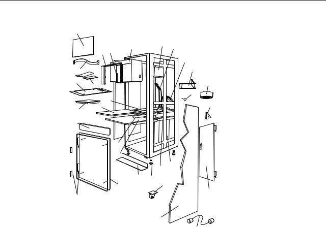
Parts listing (Type 9306 – 19-inch) Models 9QS, 9TS and 9QX, 9TX
This parts listing is for Models 9QS, 9TS and 9QX, 9TX
4
|
|
7 |
|
8 |
9 |
|
|
|
|
||
|
5 |
6 |
|
|
|
|
|
|
|
|
10 |
3 |
|
|
|
|
11 |
1 |
2 |
|
|
|
13 |
|
|
|
|
|
12 |
|
|
30 |
|
|
14 |
28 |
29 |
|
|
|
|
|
|
|
|
||
|
|
|
|
|
|
27 |
|
|
|
|
|
|
|
24 |
|
|
|
|
|
23 |
|
|
|
|
|
|
|
20 |
19 |
|
|
|
|
|
|
|
|
|
22 |
21 |
|
|
|
|
|
|
|
|
|
25 |
|
18 |
|
15
26
17
16
12 Hardware Maintenance Manual: IBM PC Server/Enterprise Racks
Index |
19-Inch Rack Enclosure (Type 9306) |
FRU |
1 |
Adapter Plate Options: |
|
|
PS/2 Server 85/95 |
76H3733 |
|
Model 300 |
76H3734 |
|
Model 500, 700 |
76H3734 |
2 |
Monitor Stand |
07H0061 |
3 |
Server Selector Cable |
07H0036 |
4 |
Blank Bezel (9QX, 9TX Expansion units only) |
76H0379 |
5 |
Monitor Bezel with button label |
76H0378 |
6 |
Server Selector Keypad |
07H0097 |
7 |
Monitor Housing (19-inch) |
76H0377 |
8 |
Server Selector Unit Electronics |
07H0034 |
|
See “Safety inspection guide” on page 192. |
|
9 |
Internal Cables |
06P6007 |
|
See Cable Kit Shelf Server |
|
10 |
Cable Management Arm |
76H0386 |
11 |
Cable Management Arm Single Server Tray |
76H0387 |
12 |
Pin, Cable Management Arm |
07H0089 |
13 |
Fan 220 V ac with Power Cord |
07H0063 |
14 |
Latch, Rear Door |
76H0376 |
15 |
Rear Door (19-Inch) |
76H0373 |
15 |
Hinge Set for Rear Door |
76H0389 |
16 |
External Power Cord: |
|
|
Australia |
14F1559 |
|
Europe |
14F1554 |
|
Israel |
14F1561 |
|
Italy |
14F1560 |
|
New Zealand |
14F1558 |
|
South America, India |
14F1557 |
|
U.K./Denmark |
14F1555 |
|
USA |
14F1553 |
|
External Power Cord Option - 6 Ft. |
07H0094 |
17 |
Left/Right Side Panel |
76H0374 |
18 |
Caster |
76H3626 |
19 |
NetBAY Rack Power Distribution Unit |
09N9668 |
19 |
NetBAY Front-end Power Distribution Unit |
09N9670 |
|
3-phase NEMA L21-30P line cord (200-250 Vac) for NetBAY Front-end PDU |
00N7720 |
|
3-phase IEC 309-3P+N+Gnd line cord (380-415 Vac) for NetBAY Front-end PDU |
00N7721 |
Type 9306 Models 4QS, 4QX, 9QS, 9QX, 9TS, 9TX 13
Index |
19-Inch Rack Enclosure (Type 9306) |
FRU |
|
1-phase NEMA L5-30P line cord (100-127 Vac) for NetBAY Front-end PDU |
00N7722 |
|
1-phase NEMA L6-30P line cord (200-240 Vac) for NetBAY Front-end PDU |
00N7723 |
|
1-phase IEC 309-2P+Gnd line cord (200-240 Vac) for NetBAY Front-end PDU |
00N7724 |
19 |
NetBAY Server Dual-cord Power Distribution Unit |
09N9669 |
|
Hardware Kit for NetBAY Power Distribution Units |
09N9671 |
|
Power Distribution Unit |
07H0424 |
19 |
250 V Slow Blow Fuse |
0303549 |
20 |
Keyboard Slides, (one pair) |
07H0038 |
21 |
Leveling Foot (Qty. 1) |
76H0390 |
22 |
Stabilizing Bar |
76H0375 |
23 |
Keyboard Tray, 19-Inch |
76H0381 |
24 |
Slide Rails, Server Tray (one pair) |
07H0083 |
24 |
Slide Rails, Dual Tray (one pair) |
76H0383 |
25 |
19-inch Front Compartment Door (19-Inch by 26-Inch) Includes Hinge Set and Screws |
76H0371 |
26 |
Door Hinge Set |
76H0372 |
27 |
Door Valance (9QX, 9TX, Expansion units only) |
76H0380 |
28 |
Mouse Table |
07H0079 |
29 |
Dual Server Tray |
76H0382 |
29 |
Dual Server Shelf |
76H0385 |
30 |
Single Server Tray |
76H0384 |
|
19-Inch Single Slide Shelf for an Industry Standard 19-Inch Rack. |
76H3628 |
|
Cable, SVGA-Video (15 Feet) Option |
76H3736 |
|
Monitor Power Cable (connects from monitor to Power Distribution Unit) |
07H0075 |
|
Rack Keyboard Cable (connects from Keyboard Drawer to Server Selector Unit) |
07H0067 |
|
Rack Mouse Cable (connects from Keyboard Drawer to Server Selector Unit) |
07H0069 |
14 Hardware Maintenance Manual: IBM PC Server/Enterprise Racks
Rack Enclosure Kits (Type 9306) |
FRU |
Bolt-Together Kit (19-Inch to 24-Inch, 24-Inch to 19-Inch) |
76G3627 |
•19-Inch Attachment Bracket (2 each)
•Screw 1/4-20 x 1/2 Button Head Socket Cap Allen (8 each)
•Screw 1/4-20 x 1-1/4 Socket Cap (4 each)
•Flanged Nut 1/4-20 (12 each)
•24-Inch Attachment Bracket (4 each)
Cable Kit Shelf Server (12foot cables) |
06P6007 |
•Monitor Cable
•Keyboard Cable
•Mouse Cable
•Internal Power Cable
Cable Kit Top Shelf Server (7-foot cables) |
06P6006 |
•Monitor Cable
•Keyboard Cable
•Mouse Cable
•Internal Power Cable
Type 9306 Models 4QS, 4QX, 9QS, 9QX, 9TS, 9TX 15
Rack Enclosure Kits (Type 9306) |
FRU |
Miscellaneous Parts Kit |
07H0057 |
•Rack Nut/Holder 10-32 (8 each)
•Keeper Nut 8-32 Zinc (8 each)
•Keeper Nut 10-32 (6 each)
•Screw 6-32 x 5/16 (2 each)
•Screw 6-32 x 1/4 Button Head Socket Cap Allen (8 each)
•Screw 10-32 x 3/8 Button Head Socket Cap (8 each)
•Screw 6-32 x 3/8 Button Head Socket Cap (2 each)
•Screw 1/4-20 x 1/2 Button Head Socket Cap (2 each)
•Screw 8-32 x 1/4 Button Head Socket Cap Allen (4 each)
•Screw 10-32 x 1/4 Button Head Socket Cap (2 each)
•Screw 8-32 x 1/4 Button Head Socket Cap (8 each)
•Pull-ring, 3-Inch (2 each)
•Shoulder Screw 8-32 x 3/8 (2 each)
•Standoff,.25 Hex, 6-32 FF,.5-Inch (2 each)
•Screw 8-32 x 3/8 Button Head Socket cap (2 each)
•Screw 10-24 x 1/4 Button Head Socket Allen (2 each)
•Screw 10-24 x 5/16 Button head Socket Allen (2 each)
•Keeper Nut 8-32 (2 each)
•Nut 8-32 (2 each)
•Captive Weld Nut (2 each)
•Whiz-Lock Flange Nut 1/4-20 (2 each)
•Keeper Nut 10-32 (2 each)
•Bumpers (2 each)
•Cable Ties (8 each)
Server Tray Interlock Kit |
07H0091 |
•Cam (1 each)
•Spring (1 each)
16 Hardware Maintenance Manual: IBM PC Server/Enterprise Racks
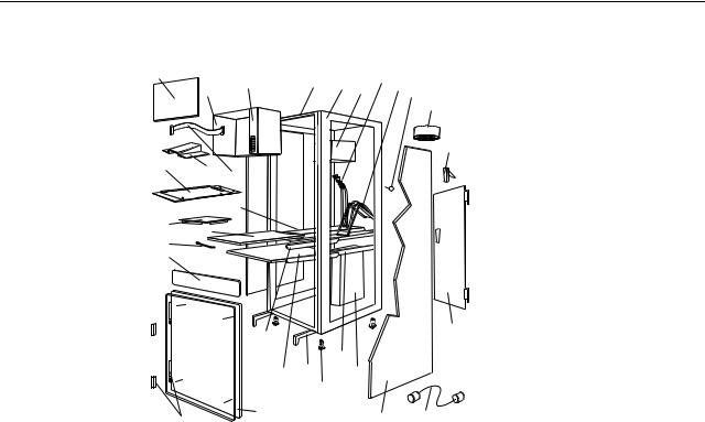
Parts listing (Type 9306 – 24-inch) Models 4QS, 4QX
This parts listing is for Models 4QS and 4QX.
4 |
6 |
7 |
8 |
|
10 |
11 12 |
|
5 |
9 |
||||||
|
|||||||
|
|
13
14
1 |
2 |
3 |
|
|
30
29 28
27
26
23 |
|
|
15 |
|
|
|
|
|
|
19 |
|
22 |
21 |
18 |
|
|
|
20 |
|
24 |
|
17 |
16 |
25 |
|
||
|
|
Type 9306 Models 4QS, 4QX, 9QS, 9QX, 9TS, 9TX 17
Index |
24-Inch Rack Enclosure (Type 9306) |
FRU |
1 |
Adapter Plate Options: |
|
|
PS/2 Server 85/95 |
76H3733 |
|
Model 300 |
76H3734 |
|
Model 500, 700 |
76H3735 |
2 |
Monitor Stand |
07H0061 |
3 |
Server Selector Cable |
07H0036 |
4 |
Blank Bezel (4QX Only) |
07H0066 |
5 |
Monitor Housing (24-Inch) |
07H0065 |
6 |
Server Selector Keypad |
07H0097 |
7 |
Rack Frame |
N/A |
8 |
Spacer (see Spacer Kit, right side at end of this FRU list) |
07H0059 |
9 |
Server Selector Unit Electronics See "Safety Notice (Multi-lingual Translations) See “Safety |
07H0034 |
|
notice (multi-lingual translations)” on page 191. |
|
10 |
Internal Cables (see Cable Kit Top Shelf Server and Cable Kit Bottom Shelf Server) |
|
11 |
Cable Management Arm |
07H0087 |
12 |
Pin, Cable Management Arm |
07H0089 |
13 |
Fan 220 V ac with Power Cord |
07H0063 |
14 |
Rear Door Latch/Lock with Key and Bracket |
07H0055 |
15 |
Rear Door (24-Inch) |
07H0047 |
16 |
External Power Cord: |
|
|
Australia |
14F1559 |
|
Europe |
14F1554 |
|
Israel |
14F1561 |
|
Italy |
14F1560 |
|
New Zealand |
14F1558 |
|
South America, India |
14F1557 |
|
U.K./Denmark |
14F1555 |
|
USA |
14F1553 |
|
External Power Cord Option - 6 Ft. |
07H0094 |
17 |
Left/Right Side Panel |
07H0049 |
18 |
NetBAY Rack Power Distribution Unit |
09N9668 |
18 |
NetBAY Front-end Power Distribution Unit |
09N9670 |
18 |
NetBAY Server Dual-cord Power Distribution Unit |
09N9669 |
|
Hardware Kit for NetBAY Power Distribution Units |
09N9671 |
18 |
Power Distribution Unit |
07H0424 |
|
250 V Slow Blow Fuse |
0303549 |
19 |
Keyboard Slides, 24-Inch (one pair) |
07H0038 |
18 Hardware Maintenance Manual: IBM PC Server/Enterprise Racks
Index |
24-Inch Rack Enclosure (Type 9306) |
FRU |
20 |
Leveling Feet (Qty. 4) |
07H0053 |
21 |
Stabilizing Leg |
07H0051 |
22 |
Keyboard Drawer, 24-Inch (with Slides and Brackets) |
07H0077 |
23 |
Slide Rails, Server Tray (one pair) |
07H0083 |
24 |
24-Inch Front Compartment Door (24-Inch by 26-Inch) |
07H0058 |
25 |
Door Hinge Set |
07H0045 |
26 |
Door Valance (4QX Only) |
07H0068 |
27 |
Handle, Server/Keyboard Tray |
07H0085 |
28 |
Server Tray |
07H0081 |
29 |
Mouse Table |
07H0079 |
30 |
Shelf, Server Tray, 24-Inch |
07H0093 |
|
Cable, SVGA-Video (15 Feet) |
76H3736 |
|
Monitor Power Cable (connects from monitor to Power Distribution Unit) |
07H0075 |
|
Rack Keyboard Cable (connects from Keyboard Drawer to Server Selector Unit) |
07H0067 |
|
Rack Mouse Cable (connects from Keyboard Drawer to Server Selector Unit) |
07H0069 |
Rack Enclosure Kits 24-inch (Type 9306) |
FRU |
Bolt-Together Kit (19-Inch to 24-Inch, 24-Inch to 19-Inch) – includes: 19-Inch Attachment |
76G3627 |
Bracket (2 each); Screw 1/4-20 x 1/2 Button Head Socket Cap; Allen (8 each); Screw 1/4-20 |
|
x 1-1/4 Socket Cap (4 each); Flanged Nut 1/4-20 (12 each); 24-Inch Attachment Bracket (4 |
|
each) |
|
Cable Kit Shelf Server (12 foot cables) – includes: Monitor Cable; Keyboard Cable; Mouse |
07H0073 |
Cable; Internal Power Cable |
|
Cable Kit Top Shelf Server (7 foot cables) – includes: Monitor Cable; Keyboard Cable; |
07H0071 |
Mouse Cable; Internal Power Cable |
|
Miscellaneous Parts Kit – includes: Rack Nut/Holder 10-32 (8 each); Keeper Nut 8-32 Zinc |
07H0057 |
(8 each); Keeper Nut 10-32 (6 each); Screw 6-32 x 5/16 (2 each); Screw 6-32 x 1/4 Button |
|
Head Socket Cap; Allen (8 each); Screw 10-32 x 3/8 Button Head Socket Cap; (8 each); |
|
Screw 6-32 x 3/8 Button Head Socket Cap; (2 each); Screw 1/4-20 x 1/2 Button Head |
|
Socket Cap; (2 each); Screw 8-32 x 1/4 Button Head Socket Cap; Allen (4 each); Screw 10- |
|
32 x 1/4 Button Head Socket Cap; (2 each); Screw 8-32 x 1/4 Button Head Socket Cap; (8 |
|
each); Pull-ring, 3-Inch (2 each); Shoulder Screw 8-32 x 3/8 (2 each); Standoff, .25 Hex, 6-32 |
|
FF, .5-Inch (2 each); Screw 8-32 x 3/8 Button Head Socket cap; (2 each); Screw 10-24 x 1/4 |
|
Button Head Socket Allen; (2 each); Screw 10-24 x 5/16 Button head Socket Allen; (2 each); |
|
Keeper Nut 8-32 (2 each); Nut 8-32 (2 each); Captive Weld Nut (2 each); Whiz-Lock Flange |
|
Nut 1/4-20 (2 each); Keeper Nut 10-32 (2 each); Bumpers (2 each); Cable Ties (8 each) |
|
Server Tray Interlock Kit – includes: Cam (1 each); Spring (1 each) |
07H0091 |
Spacer Kit, Right Side – includes: Rack Joiner (8 each); Spacer, Top and Bottom, 34-Inch (1 |
07H0059 |
each); Spacer, Body 70-Inch (2 each); Screw 10-32 x 3/8 Button Head Socket cap; (8 each); |
|
Screw 1/4-20 x 1/2 Button Head Socket cap; (8 each); Whiz-Lock Flange Nut 1/4-20 (8 |
|
each); Screw 6-32 x 3/8 Button Head Socket Cap; (6 each) |
|
Type 9306 Models 4QS, 4QX, 9QS, 9QX, 9TS, 9TX 19
20 Hardware Maintenance Manual: IBM PC Server/Enterprise Racks
Type 9306 Model 200
Features. . . . . . . . . . . . . . . . . . . . . . . . . . . . . . . . . . . . 21 Locations. . . . . . . . . . . . . . . . . . . . . . . . . . . . . . . . . . . 21 Side panel . . . . . . . . . . . . . . . . . . . . . . . . . . . . . . . . . . 21 Selector switch locations . . . . . . . . . . . . . . . . . . . . . 22 Power Distribution Unit. . . . . . . . . . . . . . . . . . . . . . 26 Blank bezel . . . . . . . . . . . . . . . . . . . . . . . . . . . . . . . . . 27 Fixed shelf . . . . . . . . . . . . . . . . . . . . . . . . . . . . . . . . . 27 Keyboard tray . . . . . . . . . . . . . . . . . . . . . . . . . . . . . . 28 Installing a flat panel monitor rack mount kit . . . 29
Removing the existing flat panel monitor stand . 29 Installing the new monitor stand . . . . . . . . . . . . . . 31 Starting the system. . . . . . . . . . . . . . . . . . . . . . . . . . 35 Configuring the selector switch . . . . . . . . . . . . . . . 35 Switching among servers . . . . . . . . . . . . . . . . . . . . 36 Advanced selector switch functions . . . . . . . . . . . 37 Resetting the selector switch. . . . . . . . . . . . . . . . . . 45 Making connections under power . . . . . . . . . . . . . 46 Parts Listing (Type 9306 Model 200) . . . . . . . . . . . 47
Features
The IBM NetBAY22, Type 9306, Model 200 Rack enclosure is a 22-U high (38.5-inch) industry-standard, 19-inch rack that houses and controls multiple IBM PC Servers/IBM Servers and related equipment.
Locations
The following sections contain information on specific equipment locations.
Note: For instructions on how to power-off the rack, see “Powering off the rack” on page 3.
Side panel
Locked Unlocked
© Copyright IBM Corp. 2001 |
21 |
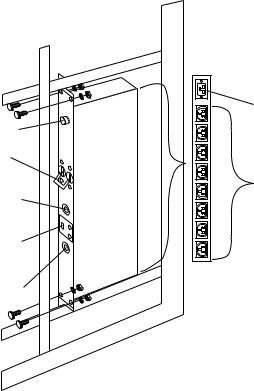
Selector switch locations
Note: For information about the IBM NetBAY Console Switch, see “IBM NetBAY console switch” on page 129.
Two |
One
M
Rese |
t |
K |
|
M |
|
Aux. |
K |
|
|
||
Three |
|
|
Two |
|
ree |
M |
Th |
K |
|
|
M |
K
M
K
Two |
Th |
ree |
M |
K
M
K
Three |
M K 
Important |
Information |
1 0
Figure 1. Selector switch in monitor compartment
22 Hardware Maintenance Manual: IBM PC Server/Enterprise Racks
Loading...