


Hyundai H-ALMS1-07H-UI151/I, H-ALMS1-09H-UI152/I, H-ALMS1-12H-UI153/I, H-ALMS1-18H-UI154/I, H-ALMT1-07H-UI155/I User Manual [ru]
...Электрический кондиционер RU воздуха
Cплит-система (мульти сплит-система)
Руководство по эксплуатации Гарантийный талон
Electric air conditioner |
|
Multi-split system |
EN |
Instruction manual |
|
Warranty card |
|
Модели / Models
Внутренний блок
Indoor unit
Наружный блок
Outdoor unit
H-ALMS1-07H-UI151/I H-ALMS1-09H-UI152/I H-ALMS1-12H-UI153/I H-ALMS1-18H-UI154/I
H-ALMT1-07H-UI155/I H-ALMT1-09H-UI156/I H-ALMT1-12H-UI157/I H-ALMT1-18H-UI158/I
H-ALMD1-07H-UI159/I H-ALMD1-09H-UI160/I H-ALMD1-12H-UI161/I H-ALMD1-18H-UI162/I
H-ALMC1-12H-UI163/I H-ALMC1-18H-UI164/I
H-ALMO1-16H2-UI145/O H-ALMO1-18H2-UI146/O H-ALMO1-24H3-UI147/O H-ALMO1-28H4-UI148/O H-ALMO1-36H4-UI149/O H-ALMO1-42H5-UI150/O
www.hyundai-hvac.com
2. |
|
|
Electric air conditioner (split system) |
|||
|
CONTENTS |
|
|
|||
|
|
|
||||
|
1.Important information |
|
3 |
|||
|
2.Safeguards |
|
3 |
|||
|
3. Technical characteristics |
|
4 |
|||
|
|
|
||||
|
4. Delivery set |
|
10 |
|||
|
|
|
||||
5.1. |
Multi split system (wall indoor type) |
|
10 |
|||
|
|
|||||
5.2. |
Multi split system (cassette indoor type) |
|
12 |
|||
|
|
|||||
5.3. |
Multi split system (duct indoor type) |
|
14 |
|||
|
|
|||||
5.4. |
Multi split system (ceiling - floor type) |
|
16 |
|||
|
|
|||||
|
6. Remote control |
|
18 |
|||
|
|
|
||||
EN

Electric air conditioner (split system) |
|
3. |
|
1. IMPORTANT INFORMATION
The appliance is designed for air cooling in domestic premises. The manufacturer reserves the right to introduce changes in design, configuration and processing of the article with a view to improve its properties without any prior notification of customers. There may be some misprints in text and digital notations of the present manual.
If after reading of this manual you have any questions concerning work and operation of the appliance, please, refer to a shop assistant or to a specialized service center for further explanations.
The article has a label with all the needed technical data and other useful information about the appliance. Use the appliance only for its intended purpose indicated in this manual.
2. SAFEGUARDS
1. |
Don’t try to install the conditioner by yourself. Call for a qualified installation specialist. |
|
2. |
While using the air conditioner, it is necessary to observe several precautions. Incorrect operation |
|
|
due to ignoring of precautions may result in personal injury of a user and other people, as well as |
|
|
in damaging of their property. |
|
3. |
The electric appliance should be under observation while operated, especially if there are any |
|
|
children near it. |
|
4. |
Don’t pass your fingers or foreign objects through an air outlet grille of indoor and outdoor units, |
|
|
since it may result in a trauma caused by a revolving fan. |
|
5. |
Don’t let children turn the conditioner on by themselves. Children may turn the conditioner on |
|
|
only under the care of adults. |
EN |
6. |
Don’t try to repair the conditioner by yourself. Internal units of the conditioner carry a voltage and |
|
|
it is life-threatening! For repair of the appliance refer to an authorized service center. |
|
7.Don’t use the appliance if it is faulty, or if it was dropped or damaged.
8.Don’t open a front panel of the appliance during its work.
9.Don’t dismantle and modify the appliance.
10.Unplug the conditioner immediately, if it emits strange odours or smoke.
11.Don’t splash and pour water and other liquids on the conditioner.
12.Always unplug the conditioner during a lighting storm.
13.Always unplug the conditioner, when it is not used.
14.Beforecleaningandmaintenanceoftheconditionerunplugit.Cleaningandmaintenanceshould be performed in accordance with instructions of this manual.
15.To ensure the effective work of the conditioner, operate it in environment described in the present manual.
16.Don’t use dangerous chemicals for cleaning of the appliance and don’t let them on the appliance.
17.When removing an air filter, don’t touch metal parts of the appliance.
18.To avoid overheating and risk of flash fire, as well as damage of internal electric network, don’t change the length of a power cord and don’t connect the appliance via extension cords.
19.To avoid electrical hazards, damaged power cord must be changed only at authorized service centers qualified professionals.
20.To avoid risk of electric shock, do not place the power cord near a heater and flammable or combustible substances.
21.Do not start or stop the unit by connecting or disconnecting electrical power.
22.To avoid electric shock, a damaged power cord should be replaced only in authorized service centers by qualified specialists.
23.To avoid electric shock, don’t place the power cord near heating appliances and flammable or combustible substances.
24.Don’t start and stop the appliance by power-up and down.
25.Don’t press the buttons of the remote control board by anything but your fingers.
26.Don’t use the appliance for purposes not intended by this user manual.
4. |
|
Electric air conditioner (split system) |
3.TECHNICAL CHARACTERISTICS
Tab.1 Multi split system DC inverter (wall indoor units)
EN
Indoor unit |
H-ALMS1- |
H-ALMS1- |
H-ALMS1- |
H-ALMS1- |
|
07H-UI151/I |
09H-UI152/I |
12H-UI153/I |
18H-UI154/I |
|
|
|
|
|
Capacity |
7000 (2,05) |
9000 (2,63) |
12000 (3,51) |
17000 (5,1) |
(cooling) BTU (kW) |
|
|
|
|
Capacity |
8000 (2,4) |
10000 (2,93) |
13000 (3,81) |
18000 (5,3) |
(heating) BTU (kW) |
|
|
|
|
Rated power consumption |
32 |
32 |
40 |
52 |
(cooling) W |
|
|
|
|
Rated power consumption |
32 |
32 |
40 |
52 |
(heating) W |
|
|
|
|
Power supply, V/Hz |
220-240~/50 |
220-240~/50 |
220-240~/50 |
220-240~/50 |
Rated power current (cooling/ |
0,15 |
0,15 |
0,19 |
0,24 |
heating) A |
|
|
|
|
Air circulation (indoor unit) |
530/430/390 |
530/430/390 |
630/550/420 |
850/750/550 |
m3/h |
|
|
|
|
Noise level (indoor unit) |
36/30/28 |
36/30/28 |
38/36/28 |
42/40/35 |
dB(A) |
|
|
|
|
Refrigerant |
R410A |
R410A |
R410A |
R410A |
Energy efficiency (cooling/ |
A/A |
A/A |
A/A |
A/A |
heating) |
|
|
|
|
Electrical protection class |
I class |
I class |
I class |
I class |
Degree of protection against |
IPX0 |
IPX0 |
IPX0 |
IPX0 |
moisture (indoor unit) |
|
|
|
|
Degree of protection against |
IP24 |
IP24 |
IP24 |
IP24 |
moisture (outdoor unit) |
|
|
|
|
Max. refrigerant pipe length, m
Refrigerant piping, Liquid side/ Gas side, (inch)
Maximum difference in level, m
Capacity of draining, L/d
Filling of Freon, g
Operating temperature range: cooling, °C
Operating temperature range: heating, °C
Net weight, indoor unit (kg)
Gross weight, indoor unit (kg)
Net dimensions, indoor unit (mm)
Packing dimensions, indoor unit (mm)
- |
- |
- |
- |
1/4+3/8 |
1/4+3/8 |
1/4+3/8 |
1/4+1/2 |
- |
- |
- |
- |
19,2 |
24 |
28,8 |
43,2 |
- |
- |
- |
- |
17~30 |
17~30 |
17~30 |
17~30 |
17~30 |
17~30 |
17~30 |
17~30 |
7 |
7 |
7,5 |
9 |
8 |
8 |
9 |
11,5 |
680x255x178 |
680x255x178 |
770x255x188 |
905x275x198 |
745x255x330 |
745x255x330 |
835x265x330 |
970x270x345 |

Electric air conditioner (split system) |
|
5. |
|
Tab.2. Multi split system DC inverter (cassette indoor units)
Indoor unit |
H-ALMT1- |
H-ALMT1- |
H-ALMT1- |
H-ALMT1- |
Panel for indoor unit |
07H-UI155/I |
09H-UI156/I |
12H-UI157/I |
18H-UI158/I |
H-SQ3-ST-UI181 |
H-SQ3-ST-UI181 |
H-SQ3-ST-UI181 |
H-SQ3-ST-UI181 |
Capacity (cooling) BTU (kW)
Capacity (heating) BTU (kW)
Rated power consumption (cooling) W
Rated power consumption (heating) W
Power supply, V/Hz
Rated power current (cooling/ heating) A
Air circulation (indoor unit) m3/h
Noise level (indoor unit) dB(A)
Refrigerant
Energy efficiency (cooling/ heating)
Electrical protection class
Degree of protection against moisture (indoor unit)
Degree of protection against moisture (outdoor unit)
Max. refrigerant pipe length, m
Refrigerant piping, Liquid side/ Gas side, (inch)
Max. refrigerant pipe length, m Capacity of draining, L/d Filling of Freon, g
Operating temperature range: cooling, °C
Operating temperature range: heating, °C
Net weight, indoor unit (kg) Net weight, panel (kg) Gross weight, indoor unit (kg)
Gross weight, panel (kg)
Net dimensions, indoor unit (mm)
Net dimensions, panel(mm)
Packing dimensions, indoor unit (mm)
Packing dimensions of panel for indoor unit (mm)
7000 (2,05) |
9000 (2,63) |
12000 (3,51) |
18000 (5,27) |
8000 (2,34) |
11000 (3,22) |
13000 (3,81) |
18000 (5,27) |
40 |
60 |
60 |
102 |
40 |
60 |
60 |
102 |
220-240~/50 |
220-240~/50 |
220-240~/50 |
220-240~/50 |
0,18 |
0,26 |
0,26 |
0,44 |
680/550/430 |
680/550/430 |
680/550/430 |
810/650/530 |
39/35/32 |
39/35/32 |
39/35/32 |
47/41/38 |
R410A |
R410A |
R410A |
R410A |
A/A |
A/A |
A/A |
A/A |
I class |
I class |
I class |
I class |
IPX0 |
IPX0 |
IPX0 |
IPX0 |
IP24 |
IP24 |
IP24 |
IP24 |
- |
- |
- |
- |
1/4+3/8 |
1/4+3/8 |
1/4+3/8 |
1/4+1/2 |
- |
- |
- |
- |
19,2 |
24 |
28,8 |
43,2 |
- |
- |
- |
- |
17~30 |
17~30 |
17~30 |
17~30 |
17~30 |
17~30 |
17~30 |
17~30 |
16 |
14,4 |
14,4 |
16,4 |
2,5 |
2,5 |
2,5 |
2,5 |
18 |
17,2 |
17,2 |
19,2 |
4,5 |
4,5 |
4,5 |
4 ,5 |
570x570x260 |
570x570x260 |
570x570x260 |
570x570x260 |
647x647x50 |
647x647x50 |
647x647x50 |
647x647x50 |
655x655x290 |
655x655x290 |
655x655x290 |
655x655x290 |
715x715x123 |
715x715x123 |
715x715x123 |
715x715x123 |
EN
6. |
|
Electric air conditioner (split system) |
Tab.3 Multi split system DC inverter (duct indoor units)
EN
Indoor unit |
H-ALMD1- |
H-ALMD1- |
H-ALMD1- |
H-ALMD1- |
|
07H-UI159/I |
09H-UI160/I |
12H-UI161/I |
18H-UI162/I |
|
|
|
|
|
Capacity |
7000 (2,05) |
9000 (2,63) |
12000 (3,51) |
18000 (5,27) |
(cooling) BTU (kW) |
|
|
|
|
Capacity |
8500 (2,49) |
11000 (3,22) |
13000 (3,81) |
20000 (5,86) |
(heating) BTU (kW) |
|
|
|
|
Rated power consumption |
62 |
62 |
62 |
107 |
(cooling) W |
|
|
|
|
Rated power consumption |
62 |
62 |
62 |
107 |
(heating) W |
|
|
|
|
Power supply, V/Hz |
220-240~/50 |
220-240~/50 |
220-240~/50 |
220-240~/50 |
Rated power current (cooling/ |
0,28 |
0,28 |
0,28 |
0,48 |
heating) A |
|
|
|
|
Air circulation (indoor unit) |
624/485/400 |
624/485/400 |
624/485/400 |
816/546/- |
m3/h |
|
|
|
|
Noise level (indoor unit) |
39 |
39 |
39 |
41 |
dB(A) |
|
|
|
|
Refrigerant |
R410A |
R410A |
R410A |
R410A |
Energy efficiency (cooling/ |
A/A |
A/A |
A/A |
A/A |
heating) |
|
|
|
|
Electrical protection class |
I class |
I class |
I class |
I class |
Degree of protection against |
IPX0 |
IPX0 |
IPX0 |
IPX0 |
moisture (indoor unit) |
|
|
|
|
Degree of protection against |
IP24 |
IP24 |
IP24 |
IP24 |
moisture (outdoor unit) |
|
|
- |
|
Max. refrigerant pipe length, m |
- |
- |
- |
|
|
|
|||
Refrigerant piping, Liquid side/ |
1/4+3/8 |
1/4+3/8 |
1/4+3/8 |
1/4+1/2 |
Gas side, (inch) |
|
|
|
|
Maximum difference in level, m |
- |
- |
- |
- |
Capacity of draining, L/d |
19,2 |
24 |
28,8 |
43,2 |
Filling of Freon, g |
- |
- |
- |
- |
Operating temperature range: |
17~30 |
17~30 |
17~30 |
17~30 |
cooling, °C |
|
|
|
|
Operating temperature range: |
17~30 |
17~30 |
17~30 |
17~30 |
heating, °C |
|
|
|
|
Net weight, indoor unit (kg) |
20 |
18 |
19 |
23 |
Gross weight, indoor unit (kg) |
25 |
22,5 |
25 |
29 |
Net dimensions, indoor unit |
700x635x210 |
700x635x210 |
700x635x210 |
920x635x210 |
(mm) |
|
|
|
|
Packing dimensions, indoor unit |
915x655x290 |
915x655x290 |
915x655x290 |
1135x655x290 |
(mm) |
|
|
|
|
Electric air conditioner (split system) |
|
7. |
|
Tab.4 Multi split system DC inverter (ceiling & floor indoor units)
Indoor unit |
H-ALMC1-12H-UI163/I |
H-ALMC1-18H-UI164/I |
|
|
|
Capacity |
12000 (3,52) |
18000 (5,27) |
(cooling) BTU (kW) |
|
|
Capacity |
13500 (3,98) |
20000 (5,86) |
(heating) BTU (kW) |
|
|
Rated power consumption |
35 |
35 |
(cooling) W |
|
|
Rated power consumption |
35 |
35 |
(heating) W |
|
|
Power supply, V/Hz |
220-240~/50 |
220-240~/50 |
Rated power current (cooling/ |
0,145 |
0,145 |
heating) A |
|
|
Air circulation (indoor unit) |
584/518/463 |
|
m3/h |
|
|
Noise level (indoor unit) |
39,6/36,7/33,1 |
|
dB(A) |
|
|
Refrigerant |
R410A |
|
Energy efficiency (cooling/ |
A/A |
|
heating) |
|
|
Electrical protection class |
I class |
|
Degree of protection against |
IPX0 |
|
moisture (indoor unit) |
|
|
Degree of protection against |
IP24 |
|
moisture (outdoor unit) |
|
|
Max. refrigerant pipe length, m |
- |
|
Refrigerant piping, Liquid side/ |
1/4+3/8 |
|
Gas side, (inch) |
||
|
||
Maximum difference in level, m |
- |
|
Capacity of draining, L/d |
28,8 |
|
Filling of Freon, g |
- |
|
Operating temperature range: |
17~30 |
|
cooling, °C |
|
|
Operating temperature range: |
17~30 |
|
heating, °C |
|
|
Net weight, indoor unit (kg) |
24 |
|
Gross weight, indoor unit (kg) |
30 |
|
Net dimensions, indoor unit |
990x660x203 |
|
(mm) |
|
|
Packing dimensions, indoor unit |
1090x745x297 |
|
(mm) |
|
800/600/500
39,6/36,7/33,1
R410A
A/A
I class
IPX0
IP24
-
1/4+1/2
-
43,2
-
17~30
17~30
24
30
990x660x203
1090x745x297
EN
8. |
|
Electric air conditioner (split system) |
Tab.5 Multi split system DC inverter (outdoor universal units)
EN
Outdoor unit |
H-ALMO1- |
H-ALMO1- |
|
16H2-UI145/O |
18H2-UI146/O |
|
|
|
Capacity |
16000 (4,69) |
18000 (5,28) |
(cooling) BTU (kW) |
|
|
Capacity |
17000 (4,98) |
21000 (6,16) |
(heating) BTU (kW) |
|
|
Rated power consumption |
1460 |
1645 |
(cooling) W |
|
|
Rated power consumption |
1380 |
1705 |
(heating) W |
|
|
Power supply, V/Hz |
220-240~/50 |
220-240~/50 |
Rated power current (cooling/ |
6,35/6,0 |
7,5/7,6 |
heating) A |
|
|
Air circulation (outdoor unit) |
- |
- |
m3/h |
|
|
Noise level (outdoor unit) |
56 |
57 |
dB(A) |
|
|
Refrigerant |
R410A |
R410A |
Energy efficiency (cooling/ |
A/A |
A/A |
heating) |
|
|
Electrical protection class |
I class |
I class |
Degree of protection against |
IPX0 |
IPX0 |
moisture (indoor unit) |
|
|
Degree of protection against moisture (outdoor unit)
Max. refrigerant pipe length, m
Refrigerant piping, Liquid side/ Gas side, (inch)
Maximum difference in level, m
Capacity of draining, L/d
Filling of Freon, g
Operating temperature range: cooling, °C
Operating temperature range: heating, °C
Net weight, outdoor unit (kg)
Gross weight, outdoor unit (kg)
Net dimensions, outdoor unit (mm)
Packing dimensions, outdoor unit (mm)
IP24 |
IP24 |
|
30 |
(Max. length for all rooms) |
30 (Max. length for all rooms) |
20 |
(Max. length for one |
20(Max. length for one |
indoor unit) |
indoor unit) |
|
1/4+3/8 |
1/4+3/8 |
|
10 |
|
10 |
--
1700 |
1450 |
0~50 |
0~50 |
-15~24 |
-15~24 |
34,5 |
45 |
37,5 |
48 |
810x310x558 |
845x320x700 |
930x400x615 |
965x395x755 |
Electric air conditioner (split system) |
|
9. |
|
H-ALMO1- |
H-ALMO1- |
H-ALMO1- |
H-ALMO1- |
24H3-UI147/O |
28H4-UI148/O |
36H4-UI149/O |
42H5-UI150/O |
|
|
|
|
24000 (7,04) |
28000 (8,21) |
36000 (10,6) |
42000 (12,3) |
25000 (7,62) |
30000 (8,79) |
41000 (11,43) |
42000 (12,3) |
2100 |
2470 |
3450 |
3830 |
2020 |
2440 |
3380 |
3410 |
220-240~/50 |
220-240~/50 |
220-240~/50 |
220-240~/50 |
8,6/8,4 |
11,2/11,1 |
15,5/15,2 |
17,5/15,6 |
- |
- |
- |
- |
58 |
60 |
61 |
66 |
R410A |
R410A |
R410A |
R410A |
A/A |
A/A |
A/A |
A/A |
I class |
I class |
I class |
I class |
IPX0 |
IPX0 |
IPX0 |
IPX0 |
EN
IP24 |
IP24 |
IP24 |
IP24 |
45 (Max. length for all |
60 (Max. length for all |
rooms) 25 (Max. length |
rooms) 30 (Max. length |
for one indoor unit) |
for one indoor unit) |
75 (Max. length for all rooms) 30 (Max. length for one indoor unit)
75 (Max. length for all rooms) 30 (Max. length for one indoor unit)
1/4+3/8 |
1/4+3/8 |
1/4+3/8 |
1/4+3/8 |
10 |
10 |
10 |
10 |
- |
- |
- |
- |
1500 |
2400 |
3000 |
3500 |
0~50 |
0~50 |
0~50 |
0~50 |
-15~24 |
-15~24 |
-15~24 |
-15~24 |
48 |
65 |
80,7 |
83,5 |
51 |
69 |
91 |
93 |
845x320x700 |
900x315x860 |
990x345x965 |
990x345x965 |
965x395x755 |
1043x395x915 |
1120x435x1100 |
1120x435x1100 |
10.
4. DELIVERY SET
Electric air conditioner (split system)
Complete set of air conditioner (split system) includes: Conditioner unit for indoor installation -1 piece (in one box)** Conditioner unit for outdoor installation -1 piece ***
Remote control board -1 piece (for each indoor unit) Batteries for remote control board - 2 pcs.
User manual -1 piece Guarantee slip -1 piece
Packing of indoor-installation unit -1 piece Packing of outdoor-installation unit -1 piece
**quantity of indoor units depends on purchased set.
***always one outdoor unit for one or several indoor units, in one complete set.
Attention!
EN
The maximum quantity of indoor units for one outdoor unit: H-ALMO1-16H2-UI145/O - 2 indoor units H-ALMO1-18H2-UI146/O - 2 indoor units H-ALMO1-24H3-UI147/O - 3 indoor units H-ALMO1-28H4-UI148/O - 4 indoor units H-ALMO1-36H4-UI149/O - 4 indoor units H-ALMO1-42H5-UI150/O - 5 indoor units
5.1. MULTI SPLIT SYSTEM DC INVERTER (WALL INDOOR TYPE)
APPLIANCE DESCRIPTION
3 |
11 |
10 |
2 |
|
7 |
|
8 |
|
1 |
4 |
|
|
9 |
|
|
|
6 5
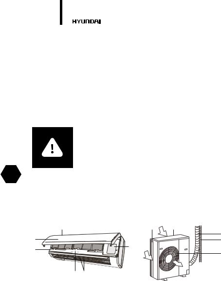
Fig. 1
The conditioner consists of indoor (one or several) and outdoor units connected by pipelines. The conditioner may be controlled from a remote control board or from an indoor unit control panel.
1.Conditioner unit for indoor installation.
2.Front panel.
3.Air-intake grille of the indoor unit.
4.Control panel (start/stop button, mode selection button) if there is no remote control board.
5.Blinds (deflectors) for distribution of treated air.
6.Air outlet of the indoor unit.
7.Copper tube for gas (freon), connection line*.
Electric air conditioner (split system) |
|
11. |
|
8.Tube for condensate removal*.
9.Air-outlet grille of the outdoor unit.
10.Conditioner unit for outdoor installation.
11.Air-intake grilles of the outdoor unit.
* not supplied
APPLIANCE CONTROL
|
|
|
|
|
|
|
|
|
EN |
|
|
|
|
|
|
|
|
|
|
|
|
|
|
|
|
|
|
|
|
|
|
|
|
|
|
|
|
|
|
|
|
|
|
|
|
|
|
|
|
|
|
|
|
|
|
|
|
|
|
|
|
|
|
|
|
|
|
|
|
|
|
|
|
|
|
|
|
|
|
|
|
|
|
|
|
|
|
|
|
|
|
|
|
|
|
|
|
|
|
|
|
|
|
|
|
|
|
|
|
Fig. 2. Description of indoor unit control panel |
|||||||||
The conditioner may be controlled from a remote control board or from an indoor unit control panel.
If the remote control board is lost or cannot be used at the moment, you may use a control button «on/off» located behind the front panel.
For that, open the front panel carefully by pulling it from the left and right.
1.Press this button once to activate the automatic mode.
2.Press this button again within 5 sec after the first pressing to switch the air conditioner to the forced cooling mode.
3.Close the front panel.
Caution!
Use this button only in case of extreme necessity. Use the remote controller, whenever possible.
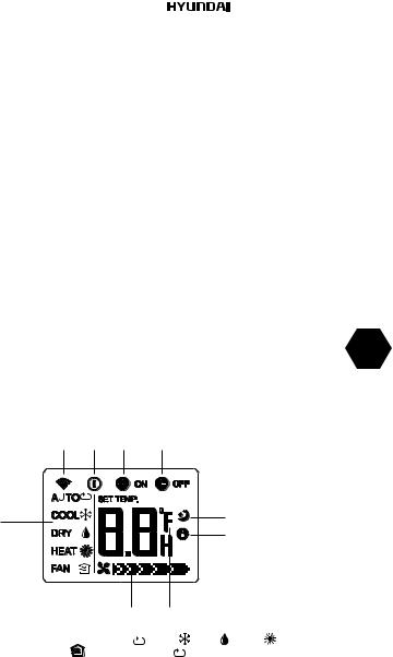
The front panel of air conditioner there is a display that shows the current temperature and defined, and indicators * display modes and settings: power, night mode, temperature, timer, compressor operation (see Fig. 3**).
The front panel of the conditioner comprises a display showing specified and current temperature, as well as indicators* reflecting modes and parameters of work: power supply, sleep mode, temperature, timer, compressor operation (see Fig. 3**).
* Presence of this function depends on the delivery lot.
12. |
|
Electric air conditioner (split system) |
5.2. MULTI SPLIT SYSTEM (CASSETTE INDOOR UNIT)
EN
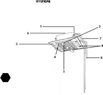
Fig. 3
1.Conditioner unit for indoor installation
2.End panel of indoor-installation unit
3.Control and indication panel
4.Blinds (deflectors) for distribution of treated air
5.Air inlet of indoor unit
6.Mounting plate
7.Tube for condensate removal
8.Copper tube for gas (freon)
Electric air conditioner (split system) |
|
|
|
13. |
||
|
|
|||||
DEVICE CONTROL |
|
|
|
|
|
|
13 |
9 |
10 |
14 11 |
12 |
|
|
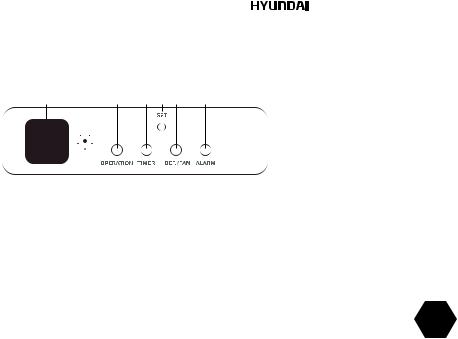
Fig.4. Description of indoor unit control board
The conditioner is controlled from a remote control board or from a control panel of the indoor unit. Control and indication board of your conditioner may visually differ from a layout view shown below. Its functions will remain the same.
9.Operation indicator
10.Timer indicator
11.Defrosting-Preheating indicator
12.Indicator alarm status
13.Infrared signal receiver
14.Button of manual (emergency) control
EN
Emergency control shall be used if the remote control board is lost or broken, or batteries are low. Using an emergency control button situated on the indoor unit control panel you may select COOL or AUTO mode of the conditioner work. Pressing this button, select a mode of the conditioner work: AUTO, COOL, the conditioner is OFF, AUTO again, etc.
1.Auto mode. The operation indicator lights up and the air conditioner works in the forced automatic mode. The remote controller can be used.
2.Forced cooling. The operation indicator blinks and the air conditioner works in the forced cooling mode. The fan speed is high for 30 min. The remote controller cannot be used.
3.Off mode. The indicator is extinguished and the air conditioner does not work. The remote controller can be used.
14. |
|
Electric air conditioner (split system) |
5.3. MULTI SPLIT SYSTEM (DUCT INDOOR UNIT)
EN
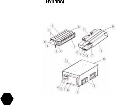
Fig. 5
1.Air outlet
2.Air inlet
3.Drain pipe
4.Liquid pipe
5.Gas pipe
6.Electric control cabinet
7.Hook
8.Indoor unit
Electric air conditioner (split system) |
|
|
|
15. |
||
|
|
|||||
DEVICE CONTROL |
|
|
|
|
|
|
13 |
9 |
10 |
11 |
12 |
|
|
Fig. 6. Description of indoor unit control board |
|
|
The conditioner is controlled from a remote control board or from a control panel of the indoor |
|
|
unit. |
|
|
Control and indication board of your conditioner may visually differ from a layout view shown |
EN |
|
below. Its functions will remain the same. |
|
|
9. Operation indicator |
|
|
10. |
Timer indicator |
|
11. |
Defrosting-Preheating indicator |
|
12. |
Indicator alarm status |
|
13. Emergency control
Emergency control shall be used if the remote control board is lost or broken, or batteries are low. Using an emergency control button situated on the indoor unit control panel you may select COOL or AUTO mode of the conditioner work. Pressing this button, select a mode of the conditioner work: AUTO, COOL, the conditioner is OFF, AUTO again, etc.
1.Auto mode. The operation indicator lights up and the air conditioner works in the forced automatic mode. The remote controller can be used.
2.Forced cooling mode. The operation indicator blinks and the air conditioner works in the forced cooling mode. The fan speed is high for 30 min. The remote controller cannot be used.
3.Off mode. The indicator is extinguished and the air conditioner does not work. The remote controller can be used.
ATTENTION!
Maintenance and service air conditioner must carry out specialist.

16. |
|
Electric air conditioner (split system) |
5.4. MULTI SPLIT SYSTEM (CEILING & FLOOR INDOOR UNIT)
Fig.. 7
1.Conditioner unit for indoor installation
2.Control and indication panel
3.Blinds (deflectors) for distribution of treated air
4.Air inlet of indoor unit
EN
DEVICE CONTROL
9 |
5 |
6 |
7 |
8 |
10 |
SET
OPERATION |
TIMER |
DEF./FAN |
ALARM |
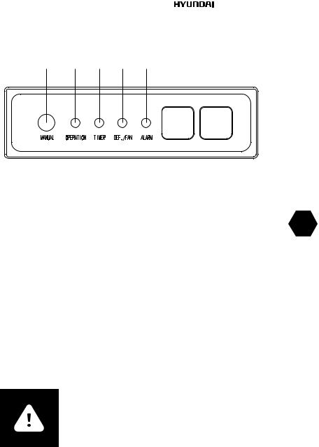
Fig. 8. Description of indoor unit control board
The conditioner is controlled from a remote control board or from a control panel of the indoor unit.
Control and indication board of your conditioner may visually differ from a layout view shown below. Its functions will remain the same.
5.Operation indicator
6.Timer indicator
7.Defrosting-Preheating indicator
8.Indicator alarm status
9.Set button. Using this button you may select operation
10.LED display. Indicator of temperature

Electric air conditioner (split system) |
|
17. |
|
Emergency control shall be used if the remote control board is lost or broken, or batteries are low. Using an emergency control button situated on the indoor unit control panel you may select COOL or AUTO mode of the conditioner work. Pressing this button, select a mode of the conditioner work: AUTO, COOL, the conditioner is OFF, AUTO again, etc.
1.Auto mode. The operation indicator lights up and the air conditioner works in the forced automatic mode. The remote controller can be used.
2.Forced cooling. The operation indicator blinks and the air conditioner works in the forced cool ing mode. The fan speed is high for 30 min. The remote controller cannot be used.
3.Off mode. The indicator is extinguished and the air conditioner does not work. The remote controller can be used.
MAINTENANCE
•Before cleaning switch the conditioner off.
•Cleaning of the indoor unit and remote control board:
•Indoor unit and remote control board should be cleaned with a dry soft cloth.
•If the indoor unit is too unclean, moisten the cloth with cold water.
•It is prohibited to clean the remote control board with moist cloth.
•In order to avoid the damage of paint or details of the conditioner, do not clean it with brushes and do not leave them on the surface of indoor unit.
•In order to avoid the damage of surface or deformation of the conditioner details, do not clean it with petrol, solvents, cleaning powders or other chemically active substances.
• |
Before a sustained interruption in the conditioner work: |
EN |
|
||
• Turn the conditioner on for several hours in the FAN mode. It will allow you to dry its inner |
|
|
|
cavities |
|
• |
Switch the conditioner off. |
|
• |
Remove the batteries from the remote control board. |
|
• |
Checks before starting: |
|
• |
Make sure that an air filter is installed. |
|
• |
Make sure that air inlet and return air grillages of the outdoor unit are not blocked by foreign |
|
|
objects. |
|
• |
Cleaning of air filter |
|
• |
Air filter cleans the air entering the conditioner from dust and foreign particles. If the filter |
|
|
is contaminated, the conditioner capacity decreases sharply. If the conditioner is operated |
|
|
permanently, the filter should be cleaned once per two weeks. |
|
• |
If the conditioner is installed in a room with dusty atmosphere, then the air filter should be |
|
|
cleaned more often. |
|
• |
To remove the filter, open the air inlet of the indoor unit panel. Press the locks to the center |
|
|
and pull the grillages down. Remove the air inlet. Remove the air filter. Clean the filter with a |
|
|
vacuum cleaner or rinse it in clean water. If the filter is contaminated heavily, clean it with a soft |
|
|
brush and wash in diluted washing solution, then dry it in a cool place. |
|
• |
While cleaning the filter with the vacuum cleaner, hold it with contaminated surface up. While |
|
|
washing the filter in water, hold it with contaminated surface down. |
|
• |
Do not dry the filter in the sun or near a fire. |
|
• |
Set the air filter to initial position and close an air inlet cover. |
|
18. |
|
Electric air conditioner (split system) |
6. REMOTE CONTROL
|
|
|
|
8 |
|
1 |
|
|
memory |
9 |
|
2 |
mode |
|
timer on |
10 |
|
|
|
||||
3 |
|
|
temp |
11 |
|
speed |
|
|
|||
|
|
|
|
||
4 |
sleep |
ion |
swingd irect |
12 |
|
13 |
|||||
5 |
|
|
|
||
|
|
|
14 |
||
6 |
maxi |
clean |
climate control |
7
EN
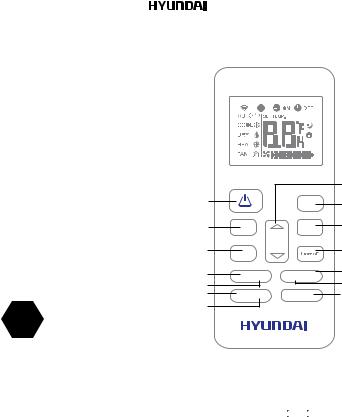
Fig. 9
1.ON/OFF Button. Operation starts when this button is pressed and stops when this button is pressed again.
2.MODE Button. Each time the button is pressed, the operationmode is selected in a sequence of following: 
3.SPEED Button. Used to select the fan speed in four steps:
4.SLEEP Button.
•Active/Disable sleep function. It can maintain the most comfortable temperature and save energy. This function is available on COOL, HEAT or AUTO mode only.
•For the detail, see sleep operation in USER S MANUAL
5.ION Button. Active/Disable ION function. When the ION function is initiated, the Ionizer/ Plasma. Dust Collector (depending on models) is energized and will help to remove pollen and impurities from the air.
6.MAXI Button. Active/Disable MAXI function. MAXI function enables the unit to reach the preset temperature at cooling or heating operation in the shortest time (if the indoor unit does not support this function, there is no corresponding operation happened when pressing this button.)
7.CLEAN Button. Active/Disable Clean function
8.UP Button. Push this button to increase the indoor temperature setting in 1oC increments to 30oC. DOWN Button. Push this button to decrease the indoor temperature setting in 1oC increments to 17oC.
9.MEMORY Button.
•Used to restore the current settings or resume previous settings.
•On the first time connecting to the power, if push the MEMORY button, the unit will operate
Electric air conditioner (split system) |
|
19. |
|
on AUTO mode, 26OC, and fan speed is Auto.
•Push this button when remote controller is on, the system will automatically revert back to the previous settings including operating mode, setting temperature, fan speed level and sleep feature(if activated). And transmit the signals to the unit.
•If pushing more than 2 seconds, the system will automatically restore the current operation settings including operating mode, setting temperature, fan speed level and sleep feature(if activated).
10.TIMER ON Button. Press this button to initiate the auto-on time sequence. Each press will increase the auto-timed setting in 30 minutes increments. When the setting time displays 10.0, each press will increase the auto-timed setting 60 minutes increments. To cancel the auto-timed program, simply adjust the auto-on time to 0.0.
11.TIMER OFF Button. Press this button to initiate the auto-off time sequence. Each press will increase the auto-timed setting in 30 minutes increments. When the setting time displays 10.0, each press will increase the auto-timed setting 60 minutes increments. To cancel the auto-timed program, simply adjust the auto-off time to 0.0
12.DIRECT Button. Used to change the louver movement and set the desired up/down air flow direction. The louver changes 6O in angle for each press. NOTE: On some models operate swing feature instead of this feature.
13.SWING Button. Used to stop or start horizontal louver auto swing feature. NOTE; On some models used to stop or start vertical louver auto swing featrue.
14.CLIMATE CONTROL Button: Push this button to initiate the CONTROL feature, the remote display is actual temperature at its location. The remote control will send this signal to the
air conditioner every 3 minutes interval until press the CLIMATE CONTROL button again.
The air conditioner will cancel the CLIMATE CONTROL feature automatically if it does not EN receive the signal during any 7 minutes interval.
OPERATING MODES
INDICATORS ON LCD
2 |
3 |
4 |
5 |
1 |
6 |
|
|
|
7 |
Fig. 10
|
9 |
8 |
|
|
Mode display |
|
), cool( |
), dry( ), heat( |
) (Not |
Displays the current operation mode. Including auto ( |
||||
applicable to cooling only models), fan( |
) and back to auto ( |
). |
|
|
Transmission Indicator
This transmission indicator lights when remote controller transmits signals to the indoor unit.
ON/OFF display
Displayed by pressing the ON/OFF button. Press the ON/OFF button again to remove.
20. |
|
Electric air conditioner (split system) |
TIMER ON display
Displayed when TIMER ON time is set.
Sleep Display
Displayed under sleeping operation.
Press the SLEEP button again to remove.If the air conditioner is on, press this button to activate the off-delay timer. Each pressing of the Timer button changes the timer setting by 1 hour in the following sequence: 1-2...24-cancel-1 and so on. As the set time passes, the air conditioner is switched off.
CLIMATE CONTROL Display(on some models)
Displayed when CLIMATE CONTROL function is activated.
Temp./Timer display
Displays the temperature setting (17 OC~30 OC). When you set the operating mode to FAN, no temperature setting is displayed. And if in the TIMER mode, shows the ON and OFF settings of the TIMER.
Fan speed display |
|
|
Displays the selected fan speed, AUTO(no display) and three fan speed levels “ |
“ (LOW) “ |
|
“ (MED) “ |
“ (HIGH) can be indicated. The fan speed is AUTO when the |
|
operating mode is either AUTO or DRY. |
|
|
NOTE:
EN
All indicators shown in the figure are for the purpose of clear presentation. But during the actual operation only the relative functional signs are shown on the display window.
HOW TO USE THE BUTTONS
Auto operation
Ensure the unit is plugged in and power is available. The OPERATION indicator on the display panel of the indoor unit starts flashing.
1.Press the MODE button to select Auto.
2.Press the UP/DOWN button to set the desired temperature. The temperature can be set within a range of 17 OC~ 30 OC in 1O OC increments.
3.Press the ON/OFFbutton to start the air conditioner.
NOTE:
In the Auto mode, the air conditioner can logically choose the mode of
Cooling, Speed, and Heating by sensing the difference between the actual ambient room temperature and the setting temperature on the remote controller.
2.In the Auto mode, you can not switch the fan speed. It has already been automatically controlled.
3.If the Auto mode is not comfortable for you , the desired mode can be selected manually.
Auto operation
Ensure the unit is plugged in and power isavailable.
1.Press the MODE button to select COOL,HEAT(cooling & heating models only) or SPEED mode.
2.Press the UP/DOWN buttons to set thedesired temperature. The temperature canbe set within a range of 17OC~ 30OC in 1OOC Cincrements.
Electric air conditioner (split system) |
|
21. |
|
3.Press the FAN button to select the fan speedin four stepsAuto, Low, Med,or High.
4.Press the ON/OFF button to start the airconditioner.
NOTE:
In the Auto mode, the air conditioner can logically choose the mode of
Cooling, Speed, and Heating by sensing the difference between the actual ambient room temperature and the setting temperature on the remote controller.
2.In the Auto mode, you can not switch the speed. It has already been automatically controlled.
3.If the Auto mode is not comfortable for you , the desired mode can be selected manually.
2
1
Fig. 11
|
|
memory |
mode |
|
timer on |
|
|
temp |
speed |
|
|
sleep |
ion |
swingd irect |
maxi |
clean |
climate control |
Dehumidifying operation
Ensure the unit is plugged in and power is available. The OPERATION indicator on the display panel of the indoor unit starts flashing.
1.Press the MODE button to select DRY mode.
2.Press the UP/DOWN buttons to set the
3desired temperature. The temperature can be set within a range of 17OC~ 30OC in 1OOC increments.
3. Press the ON/OFF button to start the air conditioner.
NOTE:
In the Dehumidifying mode, you can not switch thefan speed. It has already been automatically controlled.
EN
 Loading...