

Page 1

EDITION: DECEMBER 1999
REVISION: DECEMBER 2000
PUBLICATION NO. SM0E-1C33U6
QUICK REFERENCE INDEX
All rights reserved. No part of this Service Manual may be reproduced or stored in a retrieval system, or transmitted in any form, or
by any means, electronic, mechanical, photocopying, recording or otherwise, without the prior written permission of Nissan Motor
Company Ltd., Tokyo, Japan.
Page 2

FOREWORD
This manual contains maintenance and repair procedures for the
2000 INFINITI I30.
In order to assure your safety and the efficient functioning of the
vehicle, this manual should be read thoroughly. It is especially
important that the PRECAUTIONS in the GI section be completely
understood before starting any repair task.
All information in this manual is based on the latest product information at the time of publication. The right is reserved to make
changes in specifications and methods at any time without notice.
IMPORTANT SAFETY NOTICE
The proper performance of service is essential for both the safety of
the technician and the efficient functioning of the vehicle.
The service methods in this Service Manual are described in such a
manner that the service may be performed safely and accurately.
Service varies with the procedures used, the skills of the technician
and the tools and parts available. Accordingly, anyone using service
procedures, tools or parts which are not specifically recommended
by INFINITI must first be completely satisfied that neither personal
safety nor the vehicle’s safety will be jeopardized by the service
method selected.
Page 3

PLEASE HELP MAKE THIS SERVICE MANUAL BETTER!
Your comments are important to INFINITI and will help us to improve our Service Manuals.
Use this form to report any issues or comments you may have regarding our Service Manuals.
Please print this form and type or write your comments below. Mail or fax to:
Nissan North America, Inc.
Technical Service Information
39001 Sunrise Drive, P.O. Box 9200
Farmington Hills, MI USA 48331
FAX: (248) 488-3910
SERVICE MANUAL: Model: Year:
PUBLICATION NO. (Please photocopy back cover):
VEHICLE INFORMATION VIN: Production Date:
Please describe any issues or problems in detail:
Page number(s)
Note: Please include a copy of each page, marked with your comments.
Are the trouble diagnosis procedures logical and easy to use? (circle your answer) YES NO
If no, what page number(s)?
Please describe the issue or problem in detail:
Is the organization of the manual clear and easy to follow? (circle your answer) YES NO
Please comment:
What information should be included in INFINITI Service Manuals to better support you in servicing or
repairing customer vehicles?
Note: Please include a copy of each page, marked with your comments.
DATE: YOUR NAME: POSITION:
DEALER: DEALER NO.: ADDRESS:
CITY: STATE/PROV./COUNTRY: ZIP/POSTAL CODE:
Page 4

INCH TO METRIC CONVERSION TABLE
(Rounded-off for automotive use)
inches mm inches mm
.100 2.54 .610 15.49
.110 2.79 .620 15.75
.120 3.05 .630 16.00
.130 3.30 .640 16.26
.140 3.56 .650 16.51
.150 3.81 .660 16.76
.160 4.06 .670 17.02
.170 4.32 .680 17.27
.180 4.57 .690 17.53
.190 4.83 .700 17.78
.200 5.08 .710 18.03
.210 5.33 .720 18.29
.220 5.59 .730 18.54
.230 5.84 .740 18.80
.240 6.10 .750 19.05
.250 6.35 .760 19.30
.260 6.60 .770 19.56
.270 6.86 .780 19.81
.280 7.11 .790 20.07
.290 7.37 .800 20.32
.300 7.62 .810 20.57
.310 7.87 .820 20.83
.320 8.13 .830 21.08
.330 8.38 .840 21.34
.340 8.64 .850 21.59
.350 8.89 .860 21.84
.360 9.14 .870 22.10
.370 9.40 .880 22.35
.380 9.65 .890 22.61
.390 9.91 .900 22.86
.400 10.16 .910 23.11
.410 10.41 .920 23.37
.420 10.67 .930 23.62
.430 10.92 .940 23.88
.440 11.18 .950 24.13
.450 11.43 .960 24.38
.460 11.68 .970 24.64
.470 11.94 .980 24.89
.480 12.19 .990 25.15
.490 12.45 1.000 25.40
.500 12.70 2.000 50.80
.510 12.95 3.000 76.20
.520 13.21 4.000 101.60
.530 13.46 5.000 127.00
.540 13.72 6.000 152.40
.550 13.97 7.000 177.80
.560 14.22 8.000 203.20
.570 14.48 9.000 228.60
.580 14.73 10.000 254.00
.590 14.99 20.000 508.00
.600 15.24
METRIC TO INCH CONVERSION TABLE
(Rounded-off for automotive use)
mm inches mm inches
1 .0394 51 2.008
2 .079 52 2.047
3 .118 53 2.087
4 .157 54 2.126
5 .197 55 2.165
6 .236 56 2.205
7 .276 57 2.244
8 .315 58 2.283
9 .354 59 2.323
10 .394 60 2.362
11 .433 61 2.402
12 .472 62 2.441
13 .512 63 2.480
14 .551 64 2.520
15 .591 65 2.559
16 .630 66 2.598
17 .669 67 2.638
18 .709 68 2.677
19 .748 69 2.717
20 .787 70 2.756
21 .827 71 2.795
22 .866 72 2.835
23 .906 73 2.874
24 .945 74 2.913
25 .984 75 2.953
26 1.024 76 2.992
27 1.063 77 3.031
28 1.102 78 3.071
29 1.142 79 3.110
30 1.181 80 3.150
31 1.220 81 3.189
32 1.260 82 3.228
33 1.299 83 3.268
34 1.339 84 3.307
35 1.378 85 3.346
36 1.417 86 3.386
37 1.457 87 3.425
38 1.496 88 3.465
39 1.535 89 3.504
40 1.575 90 3.543
41 1.614 91 3.583
42 1.654 92 3.622
43 1.693 93 3.661
44 1.732 94 3.701
45 1.772 95 3.740
46 1.811 96 3.780
47 1.850 97 3.819
48 1.890 98 3.858
49 1.929 99 3.898
50 1.969 100 3.937
Page 5

TEST VALUE AND TEST LIMIT (GST ONLY — NOT APPLICABLE TO CONSULT-II)
The following is the information specified in Mode 6 of SAE J1979.
The test value is a parameter used to determine whether a system/circuit diagnostic test is “OK” or “NG” while
being monitored by the ECM during self-diagnosis. The test limit is a reference value which is specified as the
maximum or minimum value and is compared with the test value being monitored.
Items for which these data (test value and test limit) are displayed are the same as SRT code items.
These data (test value and test limit) are specified by Test ID (TID) and Component ID (CID) and can be dis-
played on the GST screen.
Self-diagnostic test item DTC
Three way catalyst function (Bank 1)
CATALYST
Three way catalyst function (Bank 2)
EVAP SYSTEM
HO2S
HO2S HTR
EGR SYSTEM EGR function
EVAP control system (Small leak)
EVAP control system purge flow monitoring P1447 06H 83H Min. 20mV
Heated oxygen sensor 1 (Bank 1)
Heated oxygen sensor 1 (Bank 2)
Heated oxygen sensor 2 (Bank 1)
Heated oxygen sensor 2 (Bank 2)
Heated oxygen sensor 1 heater (Bank 1)
Heated oxygen sensor 1 heater (Bank 2)
Heated oxygen sensor 2 heater (Bank 1)
Heated oxygen sensor 2 heater (Bank 2)
Attachment No.11
Test value
(GST display)
Test limitSRT item
Conversion
TID CID
P0420 01H 01H Max. 1/128
P0420 02H 81H Min. 1
P0430 03H 02H Max. 1/128
P0430 04H 82H Min. 1
P0440 05H 03H Max.
P1440 05H 03H Max.
P0133 09H 04H Max. 10ms
P0131 0AH 84H Min. 10mV
P0130 0BH 04H Max. 10mV
P0132 0CH 04H Max. 10mV
P0134 0DH 04H Max. 1s
P0153 11H 05H Max. 10ms
P0151 12H 85H Min. 10mV
P0150 13H 05H Max. 10mV
P0152 14H 05H Max. 10mV
P0154 15H 05H Max. 1s
P0139 19H 86H Min. 10mV/500ms
P0137 1AH 86H Min. 10mV
P0140 1BH 06H Max. 10mV
P0138 1CH 06H Max. 10mV
P0159 21H 87H Min. 10mV/500ms
P0157 22H 87H Min. 10mV
P0160 23H 07H Max. 10mV
P0158 24H 07H Max. 10mV
P0135 29H 08H Max. 20mV
P0135 2AH 88H Min. 20mV
P0155 2BH 09H Max. 20mV
P0155 2CH 89H Min. 20mV
P0141 2DH 0AH Max. 20mV
P0141 2EH 8AH Min. 20mV
P0161 2FH 0BH Max. 20mV
P0161 30H 8BH Min. 20mV
P0400 31H 8CH Min. 1
P0400 32H 8CH Min. 1
P0400 33H 8CH Min. 1
P0400 34H 8CH Min. 1
P1402 35H 0CH Max. 1
1/128mm
1/128mm
2
2
Page 6

FRONT & REAR SUSPENSION
GI
MA
CONTENTS
FRONT SUSPENSION ....................................................2
Precautions ..................................................................2
PRECAUTIONS
Preparation ..................................................................2
SPECIAL SERVICE TOOLS
COMMERCIAL SERVICE TOOLS
Noise, Vibration and Harshness (NVH)
Troubleshooting ...........................................................4
NVH TROUBLESHOOTING CHART
Components.................................................................5
On-vehicle Service.......................................................6
FRONT SUSPENSION PARTS
FRONT WHEEL ALIGNMENT
Coil Spring and Shock Absorber ...............................10
COMPONENTS
REMOVAL AND INSTALLATION
DISASSEMBLY
INSPECTION
ASSEMBLY
Stabilizer Bar .............................................................12
REMOVAL AND INSTALLATION
Transverse Link and Lower Ball Joint .......................13
REMOVAL AND INSTALLATION
INSPECTION
Service Data and Specifications (SDS).....................15
GENERAL SPECIFICATIONS (FRONT)
FRONT WHEEL ALIGNMENT (UNLADEN*1)
LOWER BALL JOINT
.........................................................2
........................................2
................................2
............................4
...................................6
.....................................6
.......................................................10
...............................11
........................................................11
...........................................................11
.............................................................12
...............................12
...............................13
...........................................................14
.....................15
.............16
...............................................16
SECTION
WHEELARCH HEIGHT (UNLADEN*)
WHEEL RUNOUT
REAR SUSPENSION.....................................................18
Precautions ................................................................18
PRECAUTIONS
Preparation ................................................................18
COMMERCIAL SERVICE TOOLS
Noise, Vibration and Harshness (NVH)
Troubleshooting .........................................................18
Components...............................................................19
On-vehicle Service.....................................................20
REAR SUSPENSION PARTS
REAR WHEEL ALIGNMENT
Removal and Installation ...........................................23
REMOVAL
INSTALLATION
Coil Spring and Shock Absorber ...............................25
REMOVAL AND INSTALLATION
DISASSEMBLY
INSPECTION
ASSEMBLY
Torsion Beam, Lateral Link and Control Rod ............26
DISASSEMBLY
INSPECTION
ASSEMBLY
Service Data and Specifications (SDS).....................28
GENERAL SPECIFICATIONS (REAR)
REAR WHEEL ALIGNMENT (UNLADEN*)
....................................................17
.......................................................18
...............................................................24
........................................................24
........................................................25
...........................................................25
.............................................................26
........................................................26
...........................................................26
.............................................................27
SU
.........................17
..............................18
...................................20
.....................................20
...............................25
.......................28
.................28
EM
LC
EC
FE
AT
AX
BR
ST
RS
BT
HA
SC
EL
IDX
Page 7
Precautions
SBR686C
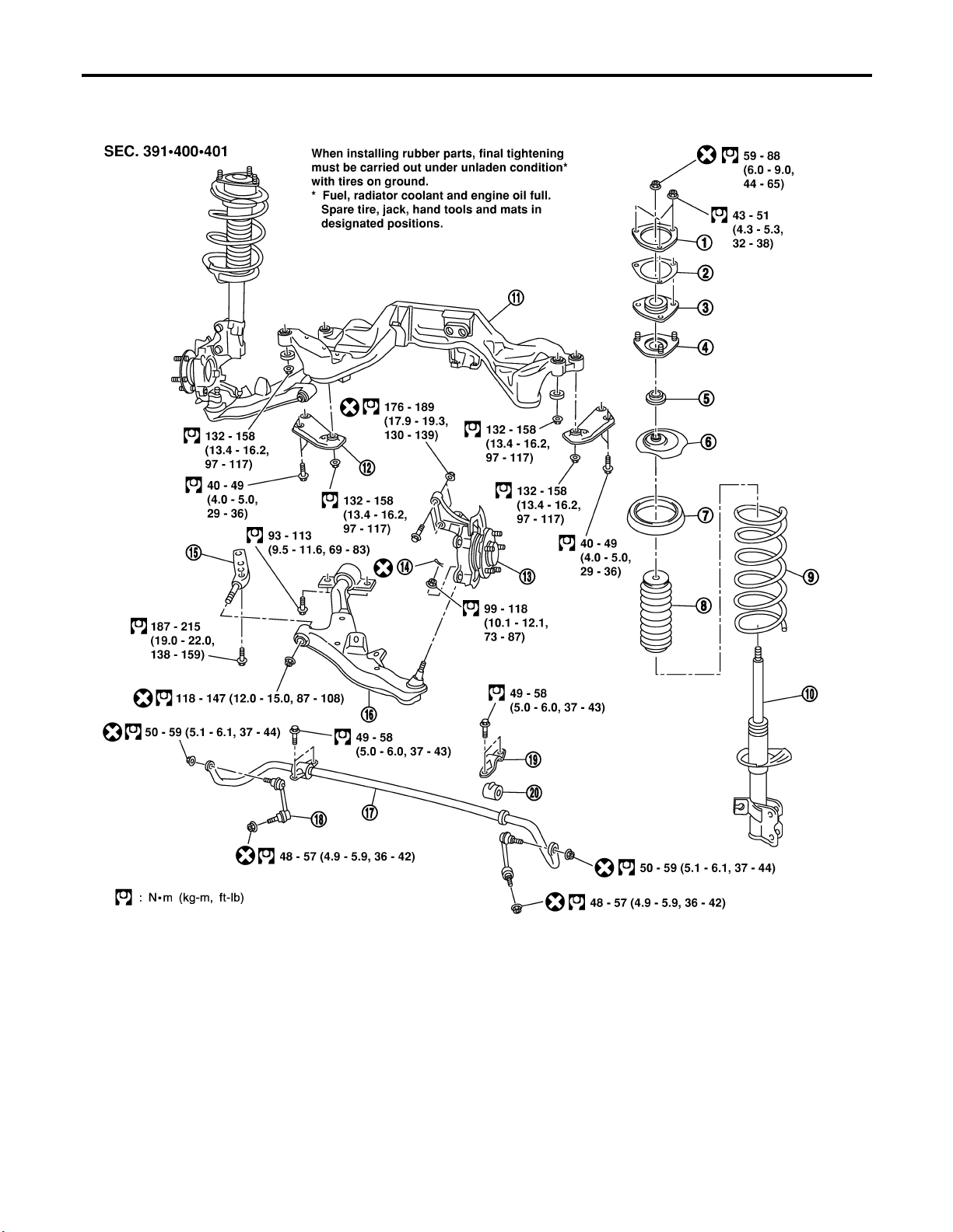
FRONT SUSPENSION
Precautions
PRECAUTIONS
! When installing rubber parts, final tightening must be car-
ried out under unladen condition* with tires on ground.
Oil will shorten the life of rubber bushes. Be sure to wipe
off any spilled oil.
*: Fuel, radiator coolant and engine oil full. Spare tire, jack,
hand tools and mats in designated positions.
! After installing removed suspension parts, check wheel
alignment and adjust if necessary.
! Use flare nut wrench when removing or installing brake
tubes.
! Always torque brake lines when installing.
! Lock nuts are unreusable parts; always use new ones.
When replacing, do not wipe the oil off the new lock nut
before tightening.
NHSU0001
Preparation
SPECIAL SERVICE TOOLS
The actual shapes of Kent-Moore tools may differ from those of special service tools illustrated here.
Tool number
(Kent-Moore No.)
Tool name
HT72520000
(J25730-A)
Ball joint remover
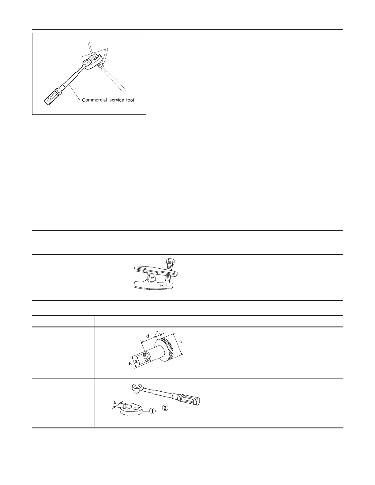
COMMERCIAL SERVICE TOOLS
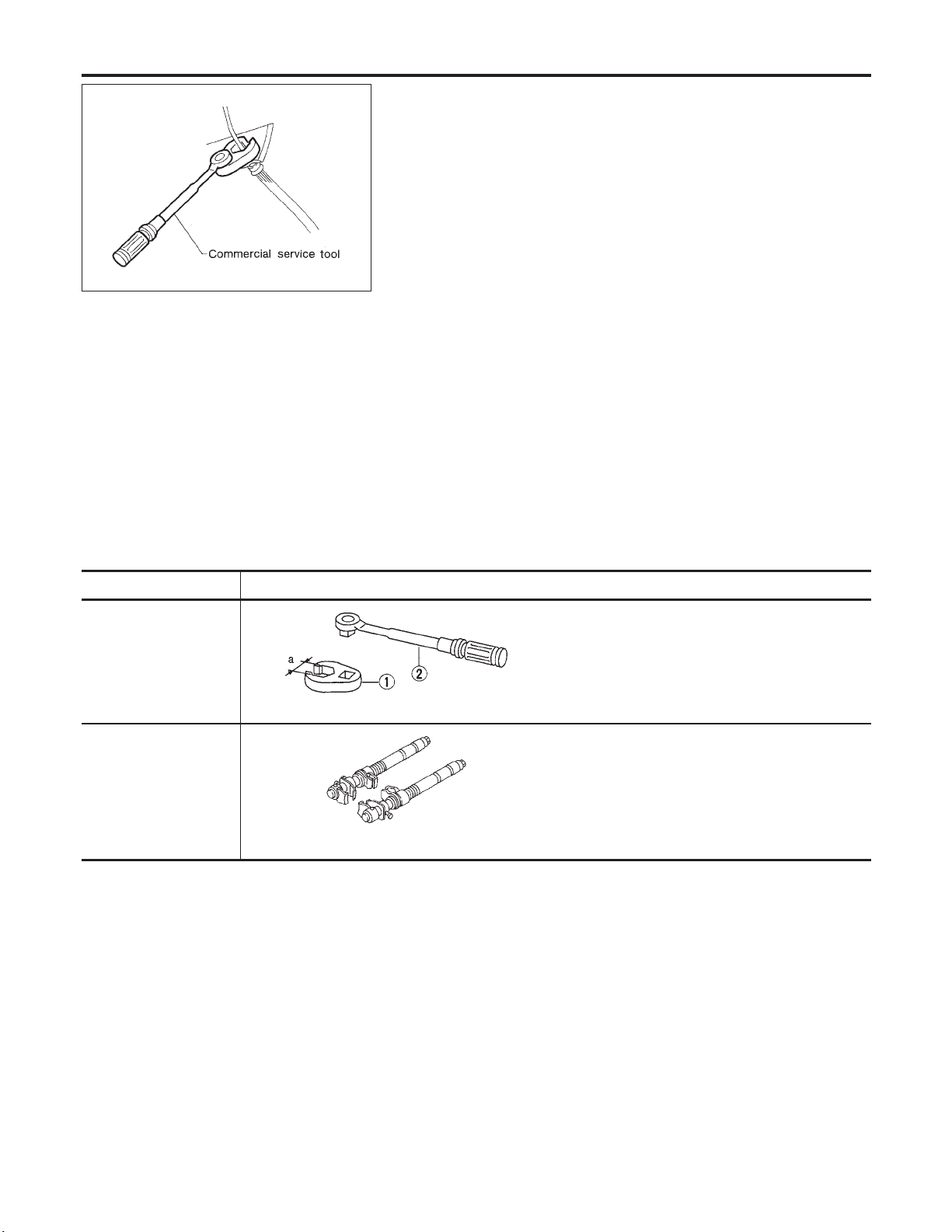
Tool name Description
Attachment Wheel alignment
1 Flare nut crowfoot
2 Torque wrench
Description
Removing tie-rod outer end and lower ball joint
NT146
Measure wheel alignment
a: Screw M24 x 1.5 pitch
b: 35 mm (1.38 in) dia.
c: 65 mm (2.56 in) dia.
d: 56 mm (2.20 in)
e: 12 mm (0.47 in)
NT148
Removing and installing each brake piping
a: 10 mm (0.39 in)
NHSU0002
NHSU0003
NT360
SU-2
Page 8

Tool name Description
FRONT SUSPENSION
Preparation (Cont’d)
Spring compressor
Removing and installing coil spring
GI
MA
NT717
EM
LC
EC
FE
AT
AX
BR
ST
RS
BT
HA
SC
EL
IDX
SU-3
Page 9

FRONT SUSPENSION
Noise, Vibration and Harshness (NVH) Troubleshooting
Noise, Vibration and Harshness (NVH)
Troubleshooting
NVH TROUBLESHOOTING CHART
Use the chart below to help you find the cause of the symptom. If necessary, repair or replace these parts.
=NHSU0004
NHSU0004S01
Reference page
SU-5, 19
Possible Cause and
SUSPECTED
PARTS
Improper installation, looseness
Noise ЧЧЧЧЧЧ ×× ××××
Shake ×××× × ×× ××××
Vibration ЧЧЧЧЧ ×× × ×
Shimmy ×××× × × ××××
Judder ××× × ××××
SUSPENSION
Poor quality
ride or handling
ЧЧЧЧЧ ×× × ××
—
SU-11, 25
Shock absorber deformation,
damage or deflection
Bushing or mounting deterioration
—
—
Parts interference
Spring fatigue
SU-6
SU-10, 23
Suspension looseness
Incorrect wheel alignment
SU-6
SU-12
Stabilizer bar fatigue
Out-of-round
—
—
Imbalance
Incorrect air pressure
—
Uneven tire wear
—
—
Deformation or damage
Non-uniformity
—
Incorrect tire size
AX-3
AX-3
DRIVE SHAFT
AXLE
—
—
SUSPENSION
TIRES
—
BR-7
ROAD WHEEL
BRAKES
ST-5
STEERING
Noise ×××××××××××××
Shake ×××××××××××××
Vibration ××××××
Shimmy ×××××××××××××
Symptom
TIRES
Judder ××××××××××××
Poor quality
ride or handling
Noise ××××××××××
Shake ××××××××××
Shimmy,
Judder
Poor quality
ROAD WHEEL
ride or handling
×: Applicable
××××××××××
×××××××××
×××××××
SU-4
Page 10

FRONT SUSPENSION
Components
Components
NHSU0005
GI
MA
EM
LC
EC
FE
AT
AX
1. Front suspension member
2. Stabilizer bar
3. Transverse link
4. Rebound stopper
5. Knuckle
6. Strut assembly
7. Coil spring
8. Strut mount plate
BR
ST
RS
BT
HA
SC
SSU009
EL
IDX
SU-5
Page 11

On-vehicle Service
SMA525A
FRONT SUSPENSION
On-vehicle Service
FRONT SUSPENSION PARTS
Check front axle and front suspension parts for excessive play,
cracks, wear or other damage.
! Shake each front wheel to check for excessive play.
! Make sure that cotter pin is inserted.
! Retighten all axle and suspension nuts and bolts to the speci-
fied torque.
Tightening torque:
Refer to “FRONT SUSPENSION”, SU-5.
! Check strut (shock absorber) for oil leakage or other damage.
! Check suspension ball joint for grease leakage and ball joint
dust cover for cracks or other damage.
If ball joint dust cover is cracked or damaged, replace transverse link.
NHSU0006
SFA392B
SFA818AA
SSU010
! Check spring height from top of wheelarch to the ground.
a) Vehicle must be unladen*, parked on a level surface, and tires
checked for proper inflation and wear (tread wear indicator
must not be showing).
*: Fuel, radiator coolant and engine oil full. Spare tire, jack,
hand tools and mats in designated positions.
b) Bounce vehicle up and down several times before measuring.
Standard height: Refer to SDS (SU-17).
c) Spring height is not adjustable. If out of specification, check for
worn springs or suspension parts.
! Check suspension ball joint end play.
a) Jack up front of vehicle and set the stands.
b) Clamp dial indicator onto transverse link and place indicator tip
on lower edge of brake caliper.
c) Make sure front wheels are straight and brake pedal is
depressed.
d) Place a pry bar between transverse link and inner rim of road
wheel.
e) While raising and releasing pry bar, observe maximum dial
indicator value.
Vertical end play: 0 mm (0 in)
f) If ball joint movement is beyond specifications, remove and
replace it.
FRONT WHEEL ALIGNMENT
NHSU0007
Before checking front wheel alignment, be sure to make a preliminary inspection (Unladen*).
*: Fuel, radiator coolant and engine oil full. Spare tire, jack, hand
tools and mats in designated positions.
SU-6
Page 12

FRONT SUSPENSION
On-vehicle Service (Cont’d)
SFA975B
SFA981B
Preliminary Inspection
Aluminum wheel
1. Check tires for wear and improper inflation.
2. Check wheels for deformation, cracks and other damage.
If deformed, remove wheel and check wheel runout.
a. Remove tire from aluminum wheel and mount on a tire balance
machine.
b. Set dial indicator as shown in the illustration.
Wheel runout (Dial indicator value):
Refer to SDS, SU-17.
3. Check front wheel bearings for looseness.
4. Check front suspension for looseness.
5. Check steering linkage for looseness.
6. Check that front shock absorbers work properly.
7. Check vehicle posture (Unladen).
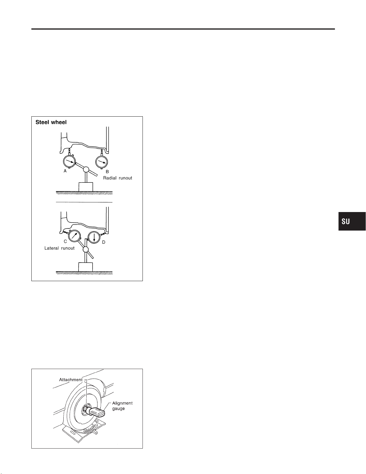
Steel wheel
1. Check tires for wear and improper inflation.
2. Check wheels for deformation, cracks and other damage.
If deformed, remove wheel and check wheel runout.
a. Remove tire from steel wheel and mount wheel on a tire bal-
ance machine.
b. Set two dial indicators as shown in the illustration.
c. Set each dial indicator to 0.
d. Rotate wheel and check dial indicators at several points
around the circumference of the wheel.
e. Calculate runout at each point as shown below.
Radial runout = (A + B)/2
Lateral runout = (C + D)/2
f. Select maximum positive runout value and the maximum
negative value.
Add the two values to determine total runout.
In case a positive or negative value is not available, use the
maximum value (negative or positive) for total runout.
If the total runout value exceeds the limit, replace steel wheel.
Wheel runout:
Refer to SDS, SU-17.
3. Check front wheel bearings for looseness.
4. Check front suspension for looseness.
5. Check steering linkage for looseness.
6. Check that front shock absorbers work properly.
7. Check vehicle posture (Unladen).
NHSU0007S01
NHSU0007S0103
NHSU0007S0104
GI
MA
EM
LC
EC
FE
AT
AX
BR
ST
RS
BT
HA
SC
EL
IDX
SU-7
Page 13

On-vehicle Service (Cont’d)
FRONT SUSPENSION
SRA096A
AFA050
Camber, Caster and Kingpin Inclination
NHSU0007S02
Camber, caster and kingpin inclination are preset at factory
and cannot be adjusted.
1. Measure camber, caster and kingpin inclination of both right
and left wheels with a suitable alignment gauge.
Camber, caster and kingpin inclination:
Refer to SDS, SU-16.
2. If camber, caster or kingpin inclination is not within
specification, inspect front suspension parts. Replace damaged or worn out parts.
Toe-in
NHSU0007S03
Measure toe-in using the following procedure.
WARNING:
! Always perform the following procedure on a flat surface.
! Make sure that no person is in front of the vehicle before
pushing it.
1. Bounce front of vehicle up and down to stabilize the posture.
2. Push the vehicle straight ahead about 5 m (16 ft).
3. Put a mark on base line of tread (rear side) of both tires at the
same height as hub center. These are measuring points.
4. Measure distance “A” (rear side).
5. Push the vehicle slowly ahead to rotate the wheels 180
degrees (1/2 turn).
If the wheels have rotated more than 180 degrees (1/2 turn), try
the above procedure again from the beginning. Never push
vehicle backward.
6. Measure distance “B” (front side).
Total toe-in:
Refer to SDS, SU-16.
SFA234AC
SFA486A
SFA439BA
7. Adjust toe-in by varying the length of steering tie-rods.
a. Loosen lock nuts.
b. Adjust toe-in by screwing tie-rods in and out.
Standard length “L”:
Refer to ST-30, “SDS”.
c. Tighten lock nuts to specified torque.
Lock nut tightening torque:
Refer to ST-15, “POWER STEERING GEAR AND LINKAGE”.
Front Wheel Turning Angle
NHSU0007S04
1. Set wheels in straight-ahead position. Then move vehicle forward until front wheels rest on turning radius gauge properly.
2. Rotate steering wheel all the way right and left; measure turning angle.
Do not hold the steering wheel on full lock for more than
15 seconds.
Wheel turning angle (Full turn):
Refer to SDS, SU-16.
SU-8
Page 14

FRONT SUSPENSION
3. Check stopper bolt head to see whether it contacts stopper
bracket at specified outside wheel angle. If not, adjust stopper
bolt to contact stopper bracket at the correct angle.
Adjust protrusion of stopper bolt before placing stopper bolt
cap.
Apply grease to face of stopper bracket that bolt touches.
Tighten stopper bolt lock nut.
: 54 - 72 N·m (5.5 - 7.3 kg-m, 40 - 53 ft-lb)
SSU023
On-vehicle Service (Cont’d)
GI
MA
EM
LC
EC
FE
AT
AX
BR
ST
RS
BT
HA
SC
EL
SU-9
IDX
Page 15
Coil Spring and Shock Absorber
FRONT SUSPENSION
Coil Spring and Shock Absorber
COMPONENTS
=NHSU0008
1. Strut mount upper plate
2. Strut spacer
3. Strut mount insulator
4. Strut mount bracket
5. Strut mount bearing
6. Spring upper seat
7. Spring rubber seat
8. Bound bumper rubber
9. Coil spring
10. Shock absorber
11. Suspension member
12. Rebound stopper
13. Wheel hub and steering knuckle
14. Cotter pin
SU-10
SSU011-A
15. Bush link pin
16. Transverse link
17. Stabilizer
18. Connecting rod
19. Stabilizer clamp
20. Bushing
Page 16

FRONT SUSPENSION
Coil Spring and Shock Absorber (Cont’d)
SFA956A
SSU002
REMOVAL AND INSTALLATION
! Remove shock absorber fixing bolt and nut (to hoodledge).
! Do not remove piston rod lock nut on vehicle.
DISASSEMBLY
1. Set shock absorber on vise, then loosen piston rod lock nut.
! Do not remove piston rod lock nut at this time.
2. Compress spring with Tool so that shock absorber mounting
insulator can be turned by hand.
WARNING:
Make sure that the pawls of the two spring compressors are
firmly hooked on the spring. The spring compressors must be
tightened alternately so as not to tilt the spring.
3. Remove piston rod lock nut.
=NHSU0009
NHSU0010
GI
MA
EM
LC
EC
FE
AT
AX
SSU003
INSPECTION
Shock Absorber Assembly
! Check for smooth operation through a full stroke, both com-
pression and extension.
! Check for oil leakage on welded or gland packing portions.
! Check piston rod for cracks, deformation or other damage.
Replace if necessary.
Mounting Insulator and Rubber Parts
! Check cemented rubber-to-metal portion for separation or
cracks. Check rubber parts for deterioration.
Replace if necessary.
Thrust Bearing
! Check thrust bearing parts for abnormal noise or excessive
rattle in axial direction.
! Replace if necessary.
Coil Spring
! Check for cracks, deformation or other damage. Replace if
necessary.
NHSU0011
NHSU0011S01
NHSU0011S02
NHSU0011S06
NHSU0011S03
BR
ST
RS
BT
HA
SC
EL
IDX
SU-11
Page 17

Coil Spring and Shock Absorber (Cont’d)
FRONT SUSPENSION
SFA508A
SFA664A
ASSEMBLY
NHSU0012
! When installing coil spring on strut, it must be positioned as
shown in the figure at left.
! Install upper spring seat with its cutout facing the outer side of
vehicle.
Stabilizer Bar
REMOVAL AND INSTALLATION
! Remove stabilizer bar.
NHSU0017
SSU027
SSU026
SFA604B
! When installing stabilizer, make sure that band and clamp face
in their correct directions.
! Make sure that slit in bushing is in the position shown in the
figure.
SU-12
Page 18

FRONT SUSPENSION
! When removing and installing stabilizer bar.
SSU027
! Install stabilizer bar with ball joint socket properly placed.
Stabilizer Bar (Cont’d)
GI
MA
EM
LC
EC
FE
AT
SFA449BB
ARA027
SFA651A
! Check stabilizer for deformation or cracks. Replace if neces-
sary.
! Check rubber bushings for deterioration or cracks. Replace if
necessary.
! Check ball joint can rotate in all directions. If movement is not
smooth and free, replace stabilizer bar connecting rod.
Transverse Link and Lower Ball Joint
REMOVAL AND INSTALLATION
1. Remove wheel bearing lock nut.
2. Remove tie-rod ball joint.
3. Remove strut lower bracket fixing bolts and nuts.
4. Separate drive shaft from knuckle by slightly tapping drive
shaft end.
Cover boots with shop towel so as not to damage them when
removing drive shaft.
5. Separate lower ball joint stud from knuckle with suitable tool.
Refer to AX-5, “FRONT AXLE — Wheel Hub and Knuckle”.
NHSU0018
AX
BR
ST
RS
BT
HA
SC
EL
IDX
SFA113A
SU-13
Page 19
Transverse Link and Lower Ball Joint (Cont’d)
SSU012
FRONT SUSPENSION
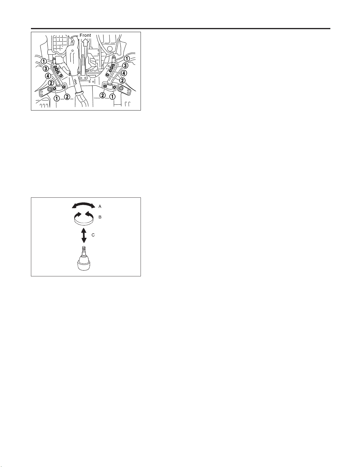
6. Remove fixing bolts.
7. Remove transverse link and lower ball joint.
8. Install fixing bolts in order of number.
Tightening torque:
Refer to “FRONT SUSPENSION”, SU-6.
9. During installation, final tightening must be carried out at curb
weight with tires on the ground.
10. After installation, check wheel alignment. Refer to “ON-VEHICLE SERVICE — Front Wheel Alignment”, SU-6.
INSPECTION
Transverse Link
! Check transverse link for damage, cracks or deformation.
Replace it if necessary.
! Check rubber bushing for damage, cracks and deformation.
Replace transverse link if necessary.
NHSU0019
NHSU0019S01
SFA858A
Lower Ball Joint
NHSU0019S02
! Check ball joint for play. Replace transverse link assembly if
any of the following cases occur. Ball stud is worn, play in axial
direction is excessive or joint is hard to swing.
Before checking, turn ball joint at least 10 revolutions so that
ball joint is properly broken in.
Swinging force “A”:
(measuring point: cotter pin hole of ball stud):
7.8 - 77.5 N (0.8 - 7.9 kg, 1.8 - 17.4 lb)
Turning torque “B”:
0.50 - 4.90 N·m (5.1 - 50 kg-cm, 4.4 - 43.4 in-lb)
Vertical end play “C”:
0 mm (0 in)
! Check dust cover for damage. Replace it and cover clamp if
necessary.
SU-14
Page 20

FRONT SUSPENSION
Service Data and Specifications (SDS)
GENERAL SPECIFICATIONS (FRONT)
Suspension type Independent MacPherson strut
Shock absorber type Double-acting hydraulic
Stabilizer bar Standard equipment
Service Data and Specifications (SDS)
=NHSU0020
GI
MA
EM
LC
EC
FE
AT
AX
BR
ST
RS
BT
HA
SC
EL
SU-15
IDX
Page 21

Service Data and Specifications (SDS) (Cont’d)
FRONT SUSPENSION
FRONT WHEEL ALIGNMENT (UNLADEN*1)
Tire size 225/50R17 215/55R16
Camber
Degree minute (Decimal degree)
Caster
Degree minute (Decimal degree)
Kingpin inclination
Degree minute (Decimal degree)
Total toe-in
Distance (A − B)
mm (in)
Angle (left plus right)
Degree minute (Decimal degree)
Wheel turning angle
Full turn*2
Inside
Degree minute (Decimal degree)
Outside
Degree minute (Decimal degree)
Minimum −1°00′ (−1.00°)
Nominal −0°15′ (−0.25°)
Maximum 0°30′ (0.50°)
Left and right difference 45′ (0.75°) or less
Minimum 2°00′ (2.00°)
Nominal 2°45′ (2.75°)
Maximum 3°30′ (3.50°)
Left and right difference 45′ (0.75°) or less
Minimum 13°30′ (13.50°)
Nominal 14°15′ (14.25°)
Maximum 15°00′ (15.00°)
Minimum 0 (0)
Nominal 1 (0.04)
Maximum 2 (0.08)
Minimum 0′ (0.00°)
Nominal 6′ (0.10°)
Maximum 12′ (0.20°)
Minimum 29°30′ (29.50°) 36°00′ (36.0°)
Nominal 33°00′ (33.0°) 39°30′ (39.50°)
Maximum 34°00′ (34.0°) 40°30′ (40.50°)
Nominal 28°30′ (28.50°) 32°00′ (32.00°)
=NHSU0021
*1: Fuel, radiator coolant and engine oil full. Spare tire, jack, hand tools and mats in designated positions.
*2: On power steering models, wheel turning force (at circumference of steering wheel) of 98 to 147 N (10 to 15 kg, 22 to 33 lb) with
engine idle.
LOWER BALL JOINT
Swinging force “A”
(Measuring point: cotter pin hole of ball stud) N (kg, lb)
Turning torque “B” N·m (kg-cm, in-lb) 0.50 - 4.90 (5.1 - 50.0, 4.4 - 43.4)
Vertical end play “C” mm (in) 0 (0)
7.8 - 77.5 (0.8 - 7.9, 1.8 - 17.4)
NHSU0022
SU-16
Page 22
FRONT SUSPENSION
Service Data and Specifications (SDS) (Cont’d)
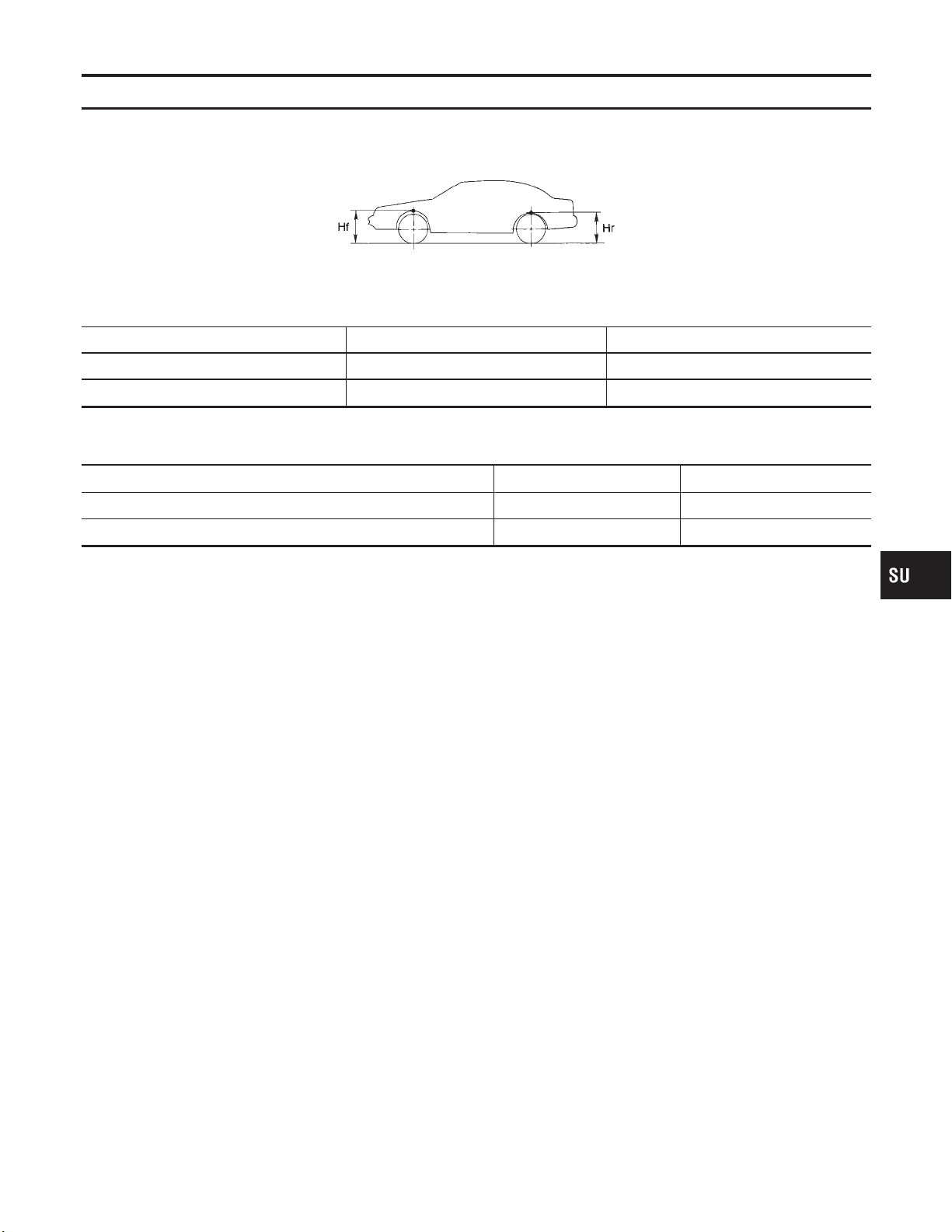
WHEELARCH HEIGHT (UNLADEN*)
Applied model Models with 225/50R17 tire Models with 215/55R16 tire
Front (Hf) mm (in) 706 (27.80) 698 (27.48)
Rear (Hr) mm (in) 694 (27.32) 683 (26.89)
*: Fuel, radiator coolant and engine oil full. Spare tire, jack, hand tools and mats in designated positions.
WHEEL RUNOUT
Wheel type Aluminum Steel wheel
Radial runout limit mm (in) 0.3 (0.012) 0.5 (0.020)
Lateral runout limit mm (in) 0.3 (0.012) 0.8 (0.031)
=NHSU0041
SFA818A
NHSU0023
GI
MA
EM
LC
EC
FE
AT
AX
BR
ST
RS
BT
HA
SC
EL
IDX
SU-17
Page 23
Precautions
SBR686C
REAR SUSPENSION
Precautions
PRECAUTIONS
! When installing each rubber part, final tightening must be
carried out under unladen condition* with tires on ground.
Oil will shorten the life of rubber bushes. Be sure to wipe
off any spilled oil.
*: Fuel, radiator coolant and engine oil full. Spare tire, jack,
hand tools and mats in designated positions.
! Use flare nut wrench when removing or installing brake
tubes.
! After installing removed suspension parts, check wheel
alignment.
! Do not jack up at the trailing arm and lateral link.
! Always torque brake lines when installing.
! Lock nuts are unreusable parts; always use new ones.
When replacing, do not wipe the oil off of the new lock nut
before tightening.
NHSU0024
COMMERCIAL SERVICE TOOLS
Tool name Description
Equivalent to
GG94310000
1 Flare nut crowfoot
2 Torque wrench
NT360
Spring compressor
NT717
Preparation
NHSU0026
Removing and installing brake piping
a: 10 mm (0.39 in)
Removing and installing coil spring
Noise, Vibration and Harshness (NVH)
Troubleshooting
Refer to “Noise, Vibration and Harshness (NVH) Troubleshooting”,
“FRONT SUSPENSION”, SU-4.
NHSU0027
SU-18
Page 24

REAR SUSPENSION
Components
Components
NHSU0028
GI
MA
EM
LC
EC
FE
AT
AX
1. Shock absorber mounting seal
2. Coil spring
3. Shock absorber
4. Suspension member
5. Control rod
6. Lateral link
7. Torsion beam
BR
ST
RS
BT
HA
SC
SSU013
EL
IDX
SU-19
Page 25

On-vehicle Service
SMA525A
REAR SUSPENSION
On-vehicle Service
REAR SUSPENSION PARTS
Check axle and suspension parts for excessive play, wear or damage.
! Shake each rear wheel to check for excessive play.
! Retighten all nuts and bolts to the specified torque.
Tightening torque:
Refer to “REAR SUSPENSION”, SU-19.
NHSU0029
SSU014
SMA113
! Check shock absorber for oil leakage or other damage.
! Check wheelarch height. Refer to “On-vehicle Service”,
“FRONT SUSPENSION PARTS”, SU-6.
REAR WHEEL ALIGNMENT
NHSU0030
Before checking rear wheel alignment, be sure to make a preliminary inspection (Unladen*).
*: Fuel, radiator coolant and engine oil full. Spare tire, jack, hand
tools and mats in designated positions.
SFA975B
Preliminary Inspection
Aluminum wheel
NHSU0030S01
NHSU0030S0101
1. Check tires for wear and improper inflation.
2. Check wheels for deformation, cracks and other damage. If
deformed, remove wheel and check wheel runout.
a. Remove tire from aluminum wheel and mount on a tire balance
machine.
b. Set dial indicator as shown in the illustration.
Wheel runout (Dial indicator value):
Refer to SDS, SU-17.
SU-20
Page 26
REAR SUSPENSION
On-vehicle Service (Cont’d)
3. Check front wheel bearings for looseness.
4. Check front suspension for looseness.
5. Check steering linkage for looseness.
6. Check that front shock absorbers work properly.
7. Check vehicle posture (Unladen).
GI
MA
EM
SFA981B
Steel wheel
1. Check tires for wear and improper inflation.
2. Check wheels for deformation, cracks and other damage.
If deformed, remove wheel and check wheel runout.
a. Remove tire from steel wheel and mount wheel on a tire bal-
ance machine.
b. Set two dial indicators as shown in the illustration.
c. Set each dial indicator to 0.
d. Rotate wheel and check dial indicators at several points
around the circumference of the wheel.
e. Calculate runout at each point as shown below.
Radial runout = (A + B)/2
Lateral runout = (C + D)/2
f. Select maximum positive runout value and the maximum
negative value.
Add the two values to determine total runout.
In case a positive or negative value is not available, use the
maximum value (negative or positive) for total runout.
If the total runout value exceeds the limit, replace steel wheel.
Wheel runout:
Refer to SDS, SU-17.
3. Check front wheel bearings for looseness.
4. Check front suspension for looseness.
5. Check steering linkage for looseness.
6. Check that front shock absorbers work properly.
7. Check vehicle posture (Unladen).
NHSU0030S0102
LC
EC
FE
AT
AX
BR
ST
RS
BT
SFA948A
Camber
Camber is preset at factory and cannot be adjusted.
Camber:
Refer to SDS, SU-28.
! If the camber is not within specification, inspect and replace
any damaged or worn rear suspension parts.
NHSU0030S02
SU-21
HA
SC
EL
IDX
Page 27

On-vehicle Service (Cont’d)
REAR SUSPENSION
SFA614B
SFA234AC
Toe-in
NHSU0030S03
Toe-in is preset at factory and cannot be adjusted.
Measure toe-in using following procedure. If out of
specification, inspect and replace any damaged or worn rear
suspension parts.
WARNING:
! Perform following procedure always on a flat surface.
! Make sure that no person is in front of the vehicle before
pushing it.
1. Bounce rear of vehicle up and down to stabilize the posture.
2. Push the vehicle straight ahead about 5 m (16 ft).
3. Put a mark on base line of the tread (rear side) of both tires at
the same height of hub center. This mark is a measuring point.
4. Measure distance “A” (rear side).
5. Push the vehicle slowly ahead to rotate the wheels 180
degrees (1/2 turn).
If the wheels have rotated more than 180 degrees (1/2 turn), try
the above procedure again from the beginning. Never push
vehicle backward.
6. Measure distance “B” (front side).
Total toe-in: A − B
Refer to SDS, SU-28.
SU-22
Page 28

REAR SUSPENSION
Removal and Installation
Removal and Installation
NHSU0031
GI
MA
EM
LC
EC
FE
AT
AX
1. Washer
2. Bushing
3. Shock absorber mounting seal
4. Shock absorber mounting bracket
5. Distance tube
6. Bushing
7. Bound bumper cover
8. Bound bumper
9. Coil spring
10. Shock absorber
11. Torsion beam
12. Control rod
13. Lateral link
14. ABS sensor
15. Suspension member
BR
ST
RS
BT
HA
SC
SSU015
EL
IDX
SU-23
Page 29

Removal and Installation (Cont’d)
REAR SUSPENSION
SSU016
SSU017
REMOVAL
NHSU0031S01
CAUTION:
! Before removing the rear suspension assembly, discon-
nect the ABS wheel sensor from the assembly. Failure to
do so may result in damage to the sensor wires and the
sensor becoming inoperative.
! Remove suspension assembly.
1. Remove tires, then remove brake hose lock plate.
2. Disconnect parking brake cable from caliper and remove brake
caliper and rotor.
Suspend caliper assembly with wire so as not to stretch brake
hose.
Be careful not to depress brake pedal, or piston will pop out.
Make sure brake hose is not twisted.
3. Using a transmission jack, raise torsion beam a little, and
remove nuts and bolts from the trailing arm, shock absorber
assembly (lower side) and lateral link.
4. Lower transmission jack, and remove suspension.
5. Remove trunk room trim. Refer to BT-39, “Trunk Room Trim”.
6. Remove strut securing nuts (upper side). Then pull out strut
assembly.
INSTALLATION
NHSU0031S02
! Install suspension assembly.
CAUTION:
Refill with new brake fluid “DOT 3”.
Never reuse drained brake fluid.
1. Install suspension member.
a. Temporarily tighten bolt 5.
b. Tighten all bolts in numerical order shown in the figure.
Tightening torque:
Refer to SU-23.
SSU020
SSU018
2. Attach control rod to lateral link. Do not tighten bolts at this
time.
3. Attach lateral link, control rod and torsion beam to vehicle. Do
not tighten bolts at this time.
SU-24
Page 30
REAR SUSPENSION
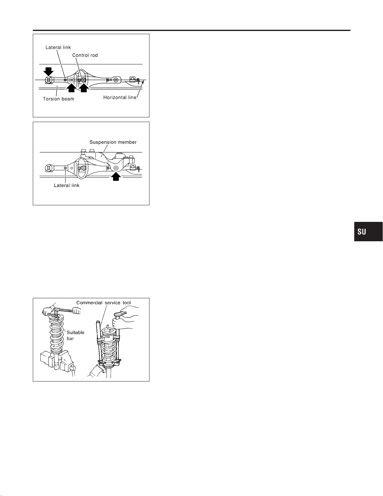
4. Using a transmission jack to lift the torsion beam, place lateral
link and control rod horizontally against torsion beam. Tighten
bolts and nuts to specified torque.
SSU019
5. Tighten lateral link at suspension member.
6. Attach shock absorber assembly to vehicle. Then tighten the
upper side of shock absorber assembly.
7. Remove transmission jack and lower torsion beam so that the
shock absorber assembly reaches full extension. Tighten torsion beam and lower side of shock absorber assembly to
specified torque.
Removal and Installation (Cont’d)
GI
MA
EM
LC
EC
FE
AT
SSU021
SRA806A
Coil Spring and Shock Absorber
REMOVAL AND INSTALLATION
Remove shock absorber upper and lower fixing nuts.
Do not remove piston rod lock nut on vehicle.
DISASSEMBLY
1. Set shock absorber in vise, then loosen piston rod lock nut.
Do not remove piston rod lock nut at this time.
2. Compress spring with Tool so that the shock absorber upper
spring seat can be turned by hand.
WARNING:
Make sure that the pawls of the two spring compressors are
firmly hooked on the spring. The spring compressors must be
tightened alternately so as not to tilt the spring.
3. Remove piston rod lock nut.
INSPECTION
Shock Absorber Assembly
! Check for smooth operation through a full stroke, both com-
pression and extension.
! Check for oil leakage on welded or gland packing portions.
! Check piston rod for cracks, deformation or other damage.
Replace if necessary.
NHSU0032
NHSU0033
NHSU0034
NHSU0034S01
AX
BR
ST
RS
BT
HA
SC
EL
IDX
Upper Rubber Seat and Bushing
Check rubber parts for deterioration or cracks.
Replace if necessary.
SU-25
NHSU0034S02
Page 31

Coil Spring and Shock Absorber (Cont’d)
REAR SUSPENSION
SRA699A
Coil Spring
NHSU0034S03
Check for cracks, deformation or other damage. Replace if
necessary.
ASSEMBLY
NHSU0035
! Locate upper spring seat as shown.
! When installing coil spring, be careful not to reverse top and
bottom direction. (Top end is flat.)
! When installing coil spring on shock absorber, it must be posi-
tioned as shown in figure at left.
CAUTION:
Do not reuse piston rod lock nut.
SFA436B
SSU025
Torsion Beam, Lateral Link and Control Rod
DISASSEMBLY
! Remove torsion beam assembly. Refer to “Removal and
Installation”, “REAR SUSPENSION”, SU-24.
! Remove lateral link and control rod from torsion beam.
INSPECTION
! Check for cracks, distortion or other damage. Replace if nec-
essary.
Standard length:
A 206.5 - 208.5 mm (8.13 - 8.21 in)
B 393.5 - 395.5 mm (15.49 - 15.57 in)
C 600 - 604 mm (23.62 - 23.78 in)
D 106 - 108 mm (4.17 - 4.25 in)
! Check all rubber parts for wear, cracks or deformation.
Replace if necessary.
NHSU0036
NHSU0037
SU-26
Page 32

REAR SUSPENSION
Torsion Beam, Lateral Link and Control Rod (Cont’d)
SRA793A
ASSEMBLY
1. Temporarily assemble lateral link and control rod.
! When installing the control rod, connect the bush with the
smaller inner diameter to the lateral link.
2. Temporarily install lateral link and control rod on torsion beam.
! When installing, place lateral link with the arrow topside.
NHSU0038
GI
MA
EM
LC
EC
FE
AT
AX
SSU022
SSU024
3. Place lateral link and control rod horizontally against torsion
beam, and tighten to the specified torque.
4. Install torsion beam assembly. Refer to “Removal and
Installation”, “REAR SUSPENSION”, SU-24.
BR
ST
RS
BT
HA
SC
EL
IDX
SU-27
Page 33

REAR SUSPENSION
Service Data and Specifications (SDS)
Service Data and Specifications (SDS)
GENERAL SPECIFICATIONS (REAR)
Suspension type Multi-link beam suspension
Shock absorber type Double-acting hydraulic
=NHSU0039
REAR WHEEL ALIGNMENT (UNLADEN*)
Camber
Degree minute (Decimal degree)
Total toe-in Distance (A − B)
mm (in)
Angle (left plus right)
Degree minute (Decimal degree)
*: Fuel, radiator coolant and engine oil full. Spare tire, jack, hand tools and mats in designated positions.
Minimum −1°45′ (−1.75°)
Nominal −1°00′ (−1.00°)
Maximum −0°15′ (−0.25°)
Minimum −3 (−0.12)
Nominal 1 (0.04)
Maximum 5 (0.20)
Minimum −16′ (−0.27°)
Nominal 5′30′′ (0.09°)
Maximum 26′ (0.43°)
NHSU0040
SU-28
Page 34

STEERING SYSTEM
GI
MA
CONTENTS
PRECAUTIONS ...............................................................2
Supplemental Restraint System (SRS) ″AIR
BAG″ and ″SEAT BELT PRE-TENSIONER″...............2
Precautions for Steering System.................................2
PREPARATION ...............................................................3
Special Service Tools ..................................................3
Commercial Service Tool .............................................4
NOISE, VIBRATION AND HARSHNESS (NVH)
TROUBLESHOOTING.....................................................5
NVH Troubleshooting Chart.........................................5
ON-VEHICLE SERVICE ..................................................6
Checking Steering Wheel Play....................................6
Checking Neutral Position on Steering Wheel ............6
PRE-CHECKING
CHECKING
Front Wheel Turning Angle..........................................6
Checking Gear Housing Movement ............................6
Checking and Adjusting Drive Belts ............................7
Checking Fluid Level ...................................................7
Checking Fluid Leakage ..............................................7
Bleeding Hydraulic System..........................................7
Checking Steering Wheel Turning Force ....................8
Checking Hydraulic System.........................................9
STEERING WHEEL AND STEERING COLUMN .........10
Components...............................................................10
Removal and Installation ...........................................10
STEERING WHEEL
STEERING COLUMN
........................................................6
...............................................................6
.................................................10
...............................................11
SECTION
Disassembly and Assembly.......................................13
Inspection...................................................................14
TILT MECHANISM
POWER STEERING GEAR AND LINKAGE ................15
Components...............................................................15
Removal and Installation ...........................................16
Disassembly...............................................................18
Inspection...................................................................19
.....................................................................19
BOOT
.....................................................................19
RACK
GEAR SUB-ASSEMBLY
GEAR HOUSING CYLINDER
TIE-ROD OUTER AND INNER SOCKETS
Assembly ...................................................................20
Adjustment .................................................................23
POWER STEERING OIL PUMP....................................25
Components...............................................................25
Pre-disassembly Inspection.......................................25
Disassembly...............................................................26
Inspection...................................................................27
Assembly ...................................................................27
SERVICE DATA AND SPECIFICATIONS (SDS) .........29
General Specifications...............................................29
Steering Wheel ..........................................................29
Steering Column ........................................................29
Steering Gear and Linkage .......................................30
Power Steering ..........................................................31
...................................................14
ST
...........................................19
....................................19
..................19
EM
LC
EC
FE
AT
AX
SU
BR
RS
BT
HA
SC
EL
IDX
Page 35

PRECAUTIONS
Supplemental Restraint System (SRS) “AIR BAG” and “SEAT BELT PRE-TENSIONER”
Supplemental Restraint System (SRS) “AIR
BAG” and “SEAT BELT PRE-TENSIONER”
The Supplemental Restraint System such as “AIR BAG” and “SEAT BELT PRE-TENSIONER” used along with
a seat belt, helps to reduce the risk or severity of injury to the driver and front passenger for certain types of
collision. The SRS system composition which is available to INFINITI I30 is as follows:
! For a frontal collision
The Supplemental Restraint System consists of driver air bag module (located in the center of the steering wheel), front passenger air bag module (located on the instrument panel on passenger side), seat belt
pre-tensioners, a diagnosis sensor unit, warning lamp, wiring harness and spiral cable.
! For a side collision
The Supplemental Restraint System consists of front side air bag module (located in the outer side of front
seat), satellite sensor, diagnosis sensor unit (one of components of air bags for a frontal collision), wiring
harness, warning lamp (one of components of air bags for a frontal collision).
Information necessary to service the system safely is included in the RS section of this Service Manual.
WARNING:
! To avoid rendering the SRS inoperative, which could increase the risk of personal injury or death
in the event of a collision which would result in air bag inflation, all maintenance should be performed by an authorized INFINITI dealer.
! Improper maintenance, including incorrect removal and installation of the SRS, can lead to per-
sonal injury caused by intentional activation of the system. For removal of Spiral Cable and Air Bag
Module, see the RS section.
! Do not use electrical test equipment on any circuit related to the SRS unless instructed to in this
Service Manual. Spiral cable and wiring harnesses covered with yellow insulation tape either just
before the harness connectors or for the complete harness are related to the SRS.
NHST0001
Precautions for Steering System
! Before disassembly, thoroughly clean the outside of the unit.
! Disassembly should be done in a clean work area. It is important to prevent the internal parts from
becoming contaminated by dirt or other foreign matter.
! Place disassembled parts in order, on a parts rack, for easier and proper assembly.
! Use nylon cloths or paper towels to clean the parts; common shop rags can leave lint that might
interfere with their operation.
! Before inspection or reassembly, carefully clean all parts with a general purpose, non-flammable
solvent.
! Before assembly, apply a coat of recommended power steering fluid* to hydraulic parts. Vaseline
may be applied to O-rings and seals. Do not use any grease.
! Replace all gaskets, seals and O-rings. Avoid damaging O-rings, seals and gaskets during instal-
lation. Perform functional tests whenever designated.
*: Genuine Nissan PSF II or equivalent. Refer to MA-11, “Fluids and Lubricants”.
NHST0003
ST-2
Page 36

PREPARATION
Special Service Tools
Special Service Tools
The actual shapes of Kent-Moore tools may differ from those of special service tools illustrated here.
Tool number
(Kent-Moore No.)
Tool name
KV48100700
(J26364)
Torque adapter
KV48102500
(J33914)
Pressure gauge adapter
ST27180001
(J25726-A)
Steering wheel puller
Description
Measuring pinion rotating torque
NT169
Measuring oil pressure
NT542
Removing steering wheel
NHST0004
GI
MA
EM
LC
EC
FE
AT
AX
HT72520000
(J25730-B)
Ball joint remover
KV48103500
(J26357 and J26357-
10)
Pressure gauge
KV48104400
(—)
Rack seal ring reformer
NT544
NT546
NT547
NT550
Removing ball joint
a: 33 mm (1.30 in)
b: 50 mm (1.97 in)
r: R11.5 mm (0.453 in)
Measuring oil pressure
Reforming teflon ring
a: 50 mm (1.97 in) dia.
b: 36 mm (1.42 in) dia.
c: 100 mm (3.94 in)
SU
BR
RS
BT
HA
SC
EL
IDX
ST-3
Page 37

Special Service Tools (Cont’d)
Tool number
(Kent-Moore No.)
Tool name
Description
PREPARATION
ST3127S000
1 GG91030000
(See J25765-A)
Torque wrench
2 HT62940000
(—)
Socket adapter
3 HT62900000
(—)
Socket adapter
Tool number Description
Oil pump attachment
NT541
NT774
Measuring turning torque
Commercial Service Tool
Disassembling and assembling oil pump
Unit: mm (in)
NHST0005
ST-4
Page 38
×: Applicable
Judder ×××××××
Symptom STEERING
Noise ЧЧЧЧЧЧЧЧЧ ЧЧЧЧЧЧ
Shake ××× ЧЧЧЧЧЧ
Vibration ЧЧЧЧЧ ××××
Shimmy ××× × ЧЧЧЧЧ
SUSPECTED PARTS
Possible cause and
Reference page
Use the chart below to help you find the cause of the symptom. If necessary, repair or replace these parts.
NOISE, VIBRATION AND HARSHNESS (NVH) TROUBLESHOOTING
ST-5
Fluid level
Air in hydraulic system
Tie-rod ball joint swinging force
Tie-rod ball joint rotating torque
Tie-rod ball joint end play
Steering gear fluid leakage
Steering wheel play
Steering gear rack sliding force
Drive belt looseness
Improper steering wheel
Improper installation or looseness or tilt lock lever
Mounting rubber deterioration
Steering column deformation or damage
Improper installation or looseness of steering column
Steering linkage looseness
DRIVE SHAFT
AXLE
SUSPENSION
TIRES
ROAD WHEEL
BRAKES
ST-7
ST-7
ST-19
ST-19
ST-19
ST-7
ST-6
ST-8
MA-13
—
ST-10
ST-6
ST-14
ST-13
ST-15
AX-3
AX-3
SU-4
SU-4
SU-4
BR-7
NVH Troubleshooting Chart
NVH Troubleshooting Chart
NHST0006S01
NHST0006
IDX
EL
SC
HA
BT
RS
BR
SU
AX
AT
FE
EC
LC
EM
MA
GI
Page 39
Checking Steering Wheel Play
ON-VEHICLE SERVICE
SST489B
SST490BA
Checking Steering Wheel Play
NHST0007
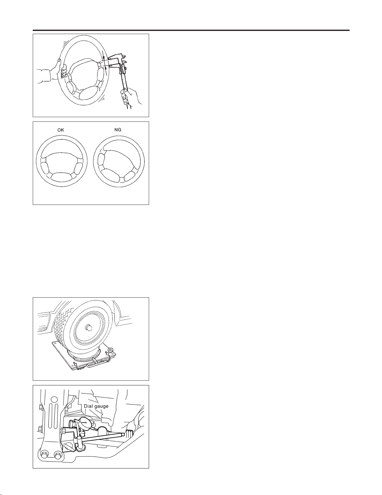
! With wheels in a straight-ahead position, check steering wheel
play.
Steering wheel play:
35 mm (1.38 in) or less
! If it is not within specification, check the following for loose or
worn components.
Steering gear assembly
Steering column
Front suspension and axle
Checking Neutral Position on Steering Wheel
PRE-CHECKING
NHST0008
NHST0008S01
! Make sure that wheel alignment is correct.
Wheel alignment:
Refer to SU-16, SDS.
! Verify that the steering gear is centered before removing the
steering wheel.
CHECKING
NHST0008S02
1. Check that the steering wheel is in the neutral position when
driving straight ahead.
2. If it is not in the neutral position, remove the steering wheel and
reinstall it correctly.
3. If the neutral position is between two teeth, loosen tie-rod lock
nuts. Turn the tie-rods by the same amount in opposite directions on both left and right sides.
SMA127
SST849C
Front Wheel Turning Angle
NHST0009
1. Rotate steering wheel all the way right and left; measure turning angle.
Turning angle of full turns:
Refer to SU-16, SDS.
2. If it is not within specification, check rack stroke.
Rack stroke “S”:
Refer to SDS, ST-30.
Checking Gear Housing Movement
NHST0010
1. Check the movement of steering gear housing during stationary steering on a dry paved surface.
! Apply a force of 49 N (5 kg, 11 lb) to steering wheel to check
the gear housing movement.
Turn off ignition key while checking.
Movement of gear housing:
±2 mm (±0.08 in) or less
2. If movement exceeds the limit, replace mount insulator after
confirming proper installation of gear housing clamps.
ST-6
Page 40

ON-VEHICLE SERVICE
Checking and Adjusting Drive Belts
SST850C
SST851C
Checking and Adjusting Drive Belts
Refer to MA-13, “Checking Drive Belts”.
Checking Fluid Level
Check fluid level, referring to the scale on reservoir tank.
Use “HOT” range for fluid temperatures of 50 to 80°C (122 to
176°F).
Use “COLD” range for fluid temperatures of 0 to 30°C (32 to 86°F).
CAUTION:
! Do not overfill.
! Recommended fluid is Genuine Nissan PSF II or equiva-
lent. Refer to MA-11, “Fluids and Lubricants”.
Checking Fluid Leakage
Check the lines for improper attachment and for leaks, cracks,
damage, loose connections, chafing and deterioration.
1. Run engine between idle speed and 1,000 rpm.
Make sure temperature of fluid in oil tank rises to 60 to 80°C
(140 to 176°F).
2. Turn steering wheel right-to-left several times.
3. Hold steering wheel at each “lock” position for five seconds
and carefully check for fluid leakage.
CAUTION:
Do not hold the steering wheel in a locked position for more
than 15 seconds.
4. If fluid leakage at connectors is noticed, loosen flare nut and
then retighten.
Do not overtighten connector as this can damage O-ring,
washer and connector.
5. If fluid leakage from power steering pump is noticed, check
power steering pump. Refer to ST-25.
6. Check rack boots for accumulation of power steering fluid.
NHST0011
NHST0012
NHST0013
GI
MA
EM
LC
EC
FE
AT
AX
SU
BR
RS
BT
HA
SC
Bleeding Hydraulic System
1. Raise front end of vehicle until wheels are clear of the ground.
2. Add fluid into oil tank to specified level. Then quickly turn steering wheel fully to right and left and lightly touch steering stoppers.
Repeat steering wheel operation until fluid level no longer
decreases.
3. Start engine.
Repeat step 2. above.
! Incomplete air bleeding will cause the following to occur. When
this happens, bleed air again.
NHST0014
ST-7
EL
IDX
Page 41

Bleeding Hydraulic System (Cont’d)
ON-VEHICLE SERVICE
a) Air bubbles in reservoir tank
b) Clicking noise in oil pump
c) Excessive buzzing in oil pump
Fluid noise may occur in the valve or oil pump. This is common
when the vehicle is stationary or while turning the steering wheel
slowly. This does not affect the performance or durability of the
system.
SST491B
SST090B
Checking Steering Wheel Turning Force
NHST0015
1. Park vehicle on a level, dry surface and set parking brake.
2. Start engine.
3. Bring power steering fluid up to adequate operating temperature. [Make sure temperature of fluid is approximately 60 to
80°C (140 to 176°F).]
Tires need to be inflated to normal pressure.
4. Check steering wheel turning force when steering wheel has
been turned 360° from the neutral position.
Steering wheel turning force:
39 N (4 kg, 9 lb) or less
5. If steering wheel turning force is out of specification, check
rack sliding force.
a. Disconnect steering column lower joint and knuckle arms from
the gear.
b. Start and run engine at idle to make sure steering fluid has
reached normal operating temperature.
c. Pull tie-rod slowly to move it from neutral position to ±11.5 mm
(±0.453 in) at speed of 3.5 mm (0.138 in)/s. Check that rack
sliding force is within specification.
Average rack sliding force:
216 - 284 N (22 - 29 kg, 49 - 64 lb)
Maximum force deviation:
98 N (10 kg, 22 lb)
d. Check sliding force outside the above range at rack speed of
40 mm (1.75 in)/s.
Rack sliding force:
Not more than 294 N (30 kg, 66 lb)
Maximum force deviation:
147 N (15 kg, 33 lb)
6. If rack sliding force is not within specification, overhaul steering gear assembly.
7. If rack sliding force is OK, inspect steering column. Refer to
ST-13.
ST-8
Page 42

ON-VEHICLE SERVICE
Checking Hydraulic System
SST834-F
Checking Hydraulic System
Before starting, check belt tension, driving pulley and tire pressure.
1. Set Tool. Open shut-off valve. Then bleed air. Refer to “Bleeding Hydraulic System”, ST-7.
2. Run engine at idle speed or 1,000 rpm.
Make sure temperature of fluid in tank rises to 60 to 80°C (140
to 176°F).
WARNING:
Warm up engine with shut-off valve fully opened. If engine is
started with shut-off valve closed, fluid pressure in oil pump
increases to maximum. This will raise oil temperature abnormally.
3. Check pressure with steering wheel fully turned to left and right
positions with engine idling at 1,000 rpm.
CAUTION:
Do not hold the steering wheel in a locked position for more
than 15 seconds.
Oil pump maximum standard pressure:
8,140 - 8,728 kPa (83 - 89 kg/cm
! If pressure reaches maximum operating pressure, system is
OK.
! If pressure increases above maximum operating pressure,
check power steering pump flow control valve. Refer to ST-25.
4. If power steering pressure is below the maximum operating
pressure, slowly close shut-off valve and check pressure
again.
CAUTION:
Do not close shut-off valve for more than 15 seconds.
! If pressure increases to maximum operating pressure, gear is
damaged. Refer to “Removal and Installation”, ST-16.
! If pressure remains below maximum operating pressure, pump
is damaged. Refer to “Disassembly”, ST-26.
5. After checking hydraulic system, remove Tool and add fluid as
necessary. Then completely bleed air out of system. Refer to
ST-7.
2
, 1,180 - 1,266 psi)
NHST0016
GI
MA
EM
LC
EC
FE
AT
AX
SU
BR
RS
ST-9
BT
HA
SC
EL
IDX
Page 43
Components
STEERING WHEEL AND STEERING COLUMN
Components
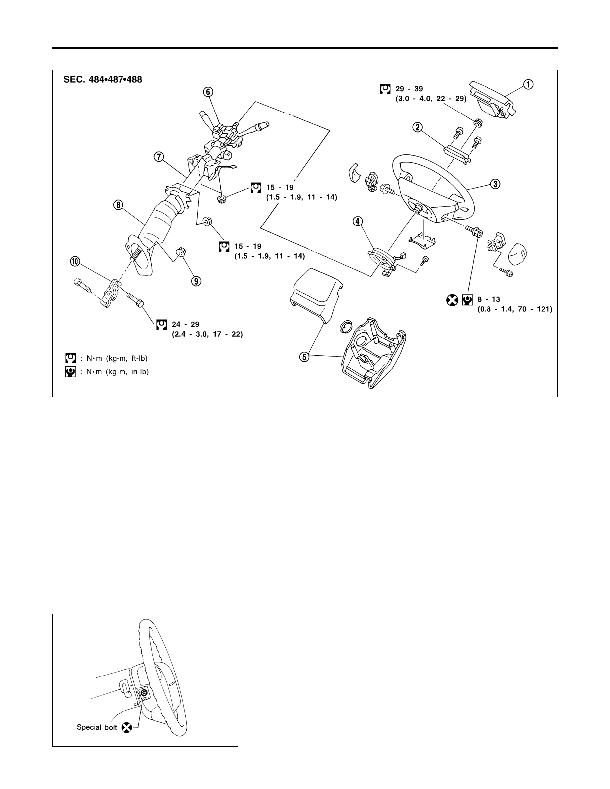
NHST0017
1. Air bag module
2. Damper
3. Steering wheel
4. Spiral cable
5. Column cover
6. Combination switch
7. Steering column assembly
8. Boot
9. Clip
10. Lower joint
CAUTION:
! The rotation of the spiral cable (SRS “Air bag” component
part) is limited. If the steering gear must be removed, set
the front wheels in the straight-ahead direction. Do not
rotate the steering column while the steering gear is
removed.
! Remove the steering wheel before removing the steering
lower joint to avoid damaging the SRS spiral cable.
Removal and Installation
STEERING WHEEL
! Remove air bag module and spiral cable.
Refer to RS-20, “Removal — Air Bag Module and Spiral Cable”.
SST852C
NHST0018
NHST0018S01
SBF812E
ST-10
Page 44

STEERING WHEEL AND STEERING COLUMN
Removal and Installation (Cont’d)
! Align spiral cable correctly when installing steering wheel.
a) Set the front wheels in the straight-ahead position.
b) Make sure that the spiral cable is in the neutral position.
The neutral position is detected by turning left 2.5 revolutions
from the right end position. Align the two marks (
CAUTION:
The spiral cable may snap due to steering operation if the
cable is installed in an improper position.
Also, with the steering linkage disconnected, the cable may
snap by turning the steering wheel beyond the limited number
of turns. (The spiral cable can be turned up to 2.5 turns from
the neutral position to both the right and left.)
).
GI
MA
EM
LC
EC
FE
AT
SRS266
SST853C
SST329C
! Remove damper for steering wheel.
! Remove steering wheel with Tool.
STEERING COLUMN
! Remove key interlock cable.
! When installing steering column, fingertighten all lower bracket
and clamp retaining bolts; then tighten them securely. Do not
apply undue stress to steering column.
! When attaching coupling joint, be sure tightening bolt faces
cutout portion.
NHST0018S02
AX
SU
BR
RS
BT
HA
SC
EL
IDX
SST800A
ST-11
Page 45

STEERING WHEEL AND STEERING COLUMN
Removal and Installation (Cont’d)
! Align slit of lower joint with projection on dust cover. Insert joint
until surface A contacts surface B.
CAUTION:
After installation, turn steering wheel to make sure it moves
smoothly. Ensure the number of turns are the same from the
straight forward position to left and right locks. Be sure that
the steering wheel is in a neutral position when driving
straight ahead.
SST491C
ST-12
Page 46

STEERING WHEEL AND STEERING COLUMN
Disassembly and Assembly
Disassembly and Assembly
=NHST0019
GI
MA
EM
LC
EC
FE
AT
AX
1. Combination switch
2. Lock nut
3. Jacket tube assembly
4. Tilt lever
5. Tilt lever stopper
6. Steering column mounting bracket
7. Spring
8. Adjust bolt
9. Adjust bolt stopper
! When disassembling and assembling, unlock steering lock
with key.
! Remove combination switch.
! Install lock nut on steering column shaft and tighten the nut.
10. Nut
11. Column shaft assembly
12. Steering column lower cover
13. Lower joint
SU
SST854CA
BR
RS
BT
HA
SC
EL
IDX
SST490C
ST-13
Page 47

STEERING WHEEL AND STEERING COLUMN
Disassembly and Assembly (Cont’d)
! Steering lock
a) Break self-shear type screws with a drill or other appropriate
tool.
SST741A
b) Install new self-shear type screws and then cut off self-shear
type screw heads.
SST742A
SST855C
Inspection
NHST0020
! When steering wheel does not turn smoothly, check the steer-
ing column as follows and replace damaged parts.
a) Check column bearings for damage or unevenness. Lubricate
with recommended multi-purpose grease or replace steering
column as an assembly, if necessary.
b) Check jacket tube for deformation or breakage. Replace if
necessary.
! When the vehicle comes into a light collision, check length “L”.
Steering column length “L”:
542 - 544 mm (21.34 - 21.42 in)
If out of the specifications, replace steering column as an assembly.
SST582B
TILT MECHANISM
NHST0020S01
! After installing steering column, check tilt mechanism opera-
tion.
ST-14
Page 48

POWER STEERING GEAR AND LINKAGE
Components
Components
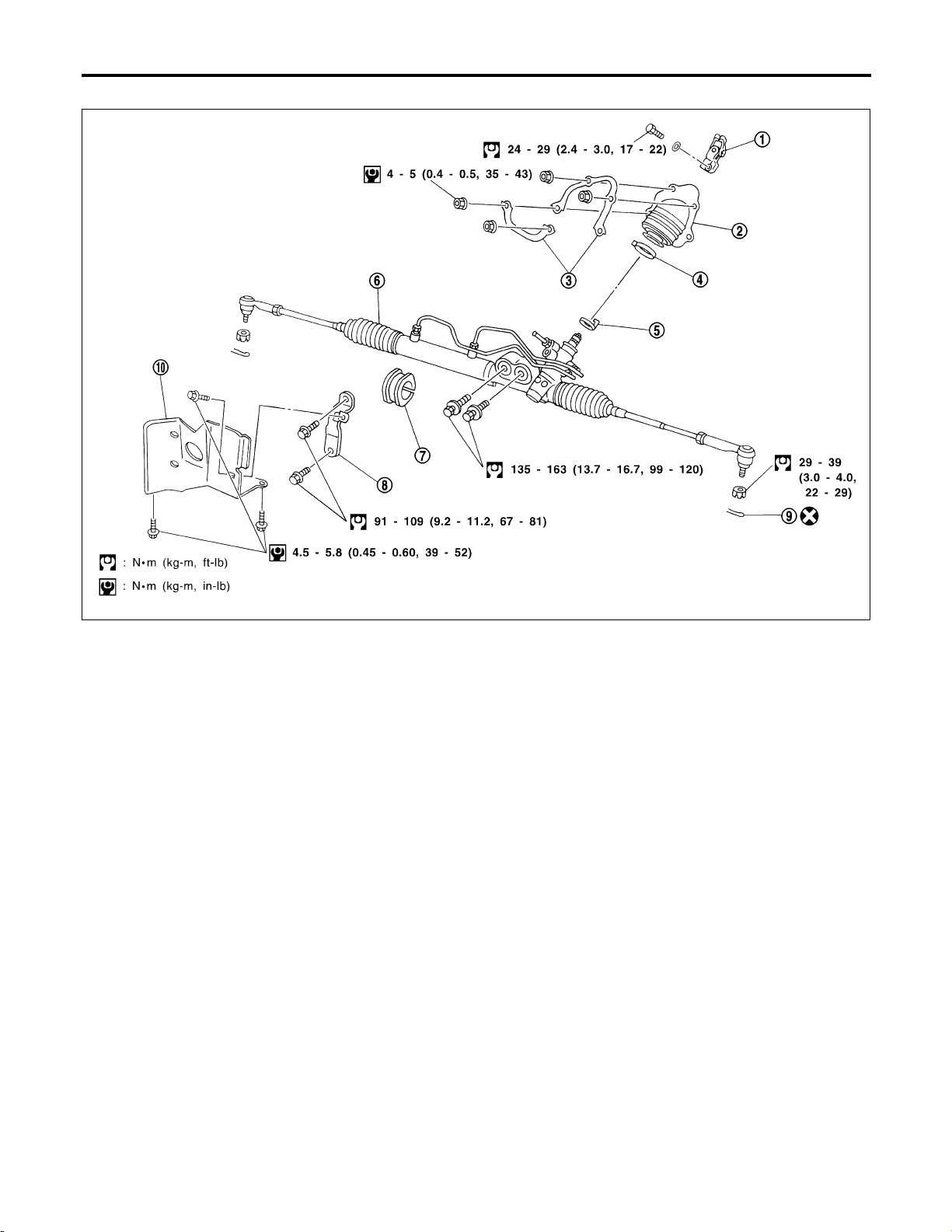
NHST0021
GI
MA
EM
LC
EC
FE
AT
AX
1. Rear cover cap
2. Gear sub-assembly
3. O-ring
4. Shim
5. Lock nut
6. Adjusting screw
7. Spring
8. Diaphragm spring
9. Washer
10. Spring seat
11. Retainer
12. Gear housing
13. Center bushing
14. Rack oil seal
15. Rack assembly
16. Rack seal ring
17. O-ring
18. Rack oil seal
19. End cover assembly
20. Boot band
21. Dust boot
22. Boot band
23. Spacer ring
24. Lock plate
25. Tie-rod inner socket
26. Tie-rod outer socket
27. Cotter pin
28. Gear housing tube
SU
BR
RS
BT
HA
SC
SST856C
EL
IDX
ST-15
Page 49
Removal and Installation
POWER STEERING GEAR AND LINKAGE
Removal and Installation
NHST0022
1. Lower joint
2. Hole cover
3. Insulator bracket
4. Clamp
5. Rear cover cap
6. Gear and linkage assembly
7. Rack mounting insulator
SST857C
8. Gear housing mounting bracket
9. Cotter pin
10. Heat insulator
ST-16
Page 50

POWER STEERING GEAR AND LINKAGE
Removal and Installation (Cont’d)
CAUTION:
! The rotation of the spiral cable (SRS “Air bag” component
part) is limited. If the steering gear must be removed, set
the front wheels in the straight-ahead direction. Do not
rotate the steering column while the steering gear is
removed.
! Remove the steering wheel before removing the steering
lower joint to avoid damaging the SRS spiral cable.
! Detach tie-rod outer sockets from knuckle arms with Tool.
1. Remove front exhaust tube. Refer to FE-11, “Removal and
SFA455BC
Installation”.
2. Set a suitable transmission jack under transaxle.
3. Remove center member and rear engine mounting. Refer to
EM-57, “Removal”.
4. Remove front stabilizer bar. Refer to SU-12, “Removal and
Installation”.
5. Remove steering gear assembly.
GI
MA
EM
LC
EC
FE
AT
SST858C
SST859C
! Install pipe connector.
! Observe specified tightening torque when tightening high-pres-
sure and low-pressure pipe connectors. Excessive tightening
will damage threads of connector or O-ring.
Connector tightening torque:
1 Low-pressure side
27 - 39 N·m (2.8 - 4.0 kg-m, 20 - 29 ft-lb)
2 High-pressure side
15 - 25 N·m (1.5 - 2.5 kg-m, 11 - 18 ft-lb)
! The O-ring in low-pressure pipe connector is larger than that
in high-pressure connector. Take care to install the proper
O-ring.
! Initially, tighten nut on tie-rod outer socket and knuckle arm to
29 to 39 N·m (3 to 4 kg-m, 22 to 29 ft-lb). Then tighten further
to align nut groove with first pin hole so that cotter pin can be
installed.
CAUTION:
Tightening torque must not exceed 49 N·m (5 kg-m, 36 ft-lb).
AX
SU
BR
RS
BT
HA
SC
EL
IDX
SST824A
ST-17
Page 51
POWER STEERING GEAR AND LINKAGE
Removal and Installation (Cont’d)
! Before removing lower joint from gear, set gear in neutral
(wheels in straight-ahead position). After removing lower joint,
put matching mark on pinion shaft and pinion housing to record
neutral position.
! To install, set left and right dust boots to equal deflection.
Attach lower joint by aligning matching marks of pinion shaft
and pinion housing.
SST860C
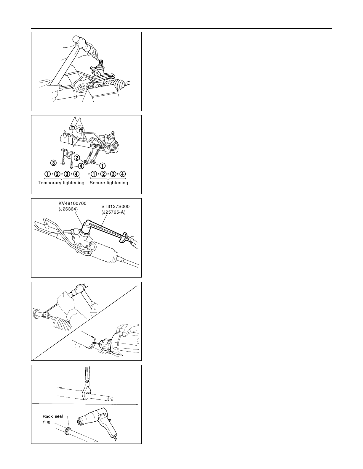
! Tighten gear housing mounting bracket bolts in the order
shown.
SST861C
SST862C
SST051C
Disassembly
NHST0023
1. Prior to disassembling, measure pinion rotating torque. Record
the pinion rotating torque as a reference.
! Before measuring, disconnect gear housing tube and
drain fluid.
! Use soft jaws when holding steering gear housing. Handle
gear housing carefully, as it is made of aluminum. Do not
grip cylinder in a vise.
2. Remove gear sub-assembly, O-ring and shim.
Gear sub-assembly cannot be disassembled. If it is faulty,
replace with a new one.
3. Remove tie-rod outer sockets and boots.
4. Loosen tie-rod inner socket by prying up staked portion, and
remove socket and spacer.
5. Remove retainer.
6. Use a 2 to 2.5 mm (0.079 to 0.098 in) diameter drill to completely remove staked portion of gear housing end.
7. Remove end cover assembly with a suitable tool.
8. Draw out rack assembly.
9. Remove rack seal ring.
! Using a heat gun, heat rack seal to approximately 40°C
(104°F).
! Remove rack seal ring.
Be careful not to damage rack.
SST052C
ST-18
Page 52
POWER STEERING GEAR AND LINKAGE
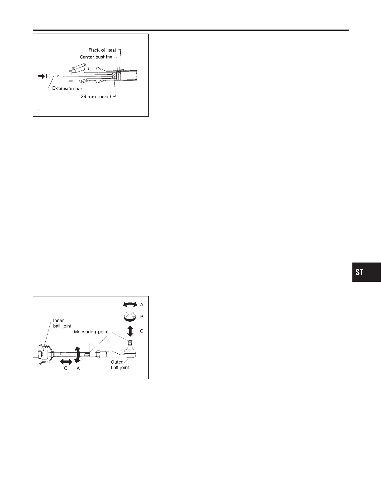
10. Remove center bushing and rack oil seal using tape wrapped
socket and extension bar.
Do not scratch inner surfaces of pinion housing.
SST472A
Disassembly (Cont’d)
GI
MA
EM
SST468C
Inspection
Thoroughly clean all parts in cleaning solvent or Genuine NISSAN
PSF II or equivalent. Blow dry with compressed air, if available.
BOOT
! Check condition of boot. If cracked excessively, replace it.
! Check boots for accumulation of power steering fluid.
RACK
Thoroughly examine rack gear. If damaged, cracked or worn,
replace it.
GEAR SUB-ASSEMBLY
! Check pinion gear. If it is worn or damaged, replace as a gear
sub-assembly.
! Manually spin bearing. If torque variations or free play are
noted, replace as a gear sub-assembly.
GEAR HOUSING CYLINDER
Check gear housing cylinder bore for scratches or other damage.
Replace if necessary.
TIE-ROD OUTER AND INNER SOCKETS
! Check ball joints for swinging force.
Tie-rod outer and inner ball joints swinging force “A”:
Refer to SDS, ST-30.
! Check ball joint for rotating torque.
Tie-rod outer ball joint rotating torque “B”:
Refer to SDS, ST-30.
! Check ball joints for axial end play.
Tie-rod outer and inner ball joints axial end play “C”:
Refer to SDS, ST-30.
! Check condition of dust cover. If cracked excessively, replace
outer tie-rod.
NHST0024
NHST0024S01
NHST0024S02
NHST0024S03
NHST0024S04
NHST0024S05
LC
EC
FE
AT
AX
SU
BR
RS
BT
HA
SC
EL
IDX
ST-19
Page 53
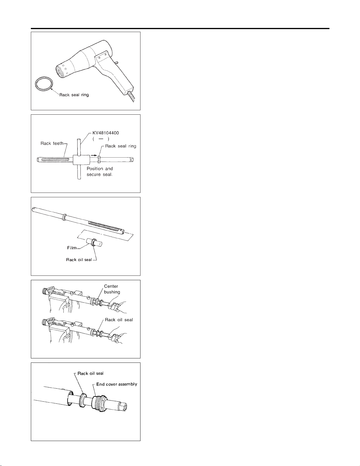
Assembly
POWER STEERING GEAR AND LINKAGE
SST083B
SST885BB
Assembly
NHST0025
1. Using a heat gun, heat new teflon rack seal ring to approximately 40°C (104°F). Then place it onto rack.
2. Using Tool, compress rack seal ring securely onto rack.
Always insert Tool from the rack gear side.
3. Insert new rack oil seal.
! Place plastic film into rack oil seal to prevent damage by
rack teeth.
! Do not forget to remove plastic film after rack oil seal is
positioned properly.
! Make sure lips of rack oil seal face each other.
SST201A
SST863C
SST321B
4. Install center bushing and rack oil seal with rack assembly.
5. Insert rack oil seal and end cover assembly to rack. Then
tighten end cover assembly.
ST-20
Page 54

POWER STEERING GEAR AND LINKAGE
6. Fasten end cover assembly to gear housing by staking.
SST073B
7. Set rack gear in neutral position.
Rack stroke “S”:
Refer to SDS, ST-30.
Assembly (Cont’d)
GI
MA
EM
LC
EC
FE
AT
SST086BA
SST864C
SST865C
8. Install adjustment shims and O-rings to gear sub-assembly.
! Install the same number of adjustment shims as before,
regardless of whether or not gear sub-assembly is replaced.
! Discard old O-rings; replace with new ones.
9. Tighten gear subassembly securing bolts to specified tightening torque.
10. Ensure that the rack is centered. Install rear cover cap so that
its protrusion is positioned as shown in figure.
11. Install diaphragm spring into gear housing.
! Always install retainer, spring washer and diaphragm spring in
that order.
! Make sure convex end (painted white) of diaphragm spring
faces outward when installing.
12. Install spring seat retainer spring and adjusting screw temporarily.
AX
SU
BR
RS
BT
HA
SC
EL
IDX
SST087B
ST-21
Page 55

Assembly (Cont’d)
POWER STEERING GEAR AND LINKAGE
13. Install lock plate to rack.
a. Temporarily install spacer ring to rack.
Discard old spacer ring; replace with a new one.
b. Install lock plate to inner socket.
Discard old lock plate; replace with a new one.
c. Apply a coat of locking sealant to inner socket threads. Screw
inner socket into rack and tighten to specified torque.
d. Clinch lock plate at rack groove location (at two points).
e. Install spacer ring to lock plate as shown in the Figure at left.
SST866C
Be careful not to damage spacer ring during installation
14. Tighten outer socket lock nut.
Tie-rod length “L”:
Refer to SDS, ST-30.
SST867C
SST086BA
SST967A
15. Measure rack stroke.
Rack stroke “S”:
Refer to SDS, ST-30.
16. Before installing boot, coat the contact surfaces between boot
and tie-rod with grease.
17. Install boot bands.
! Securely install boot band to boot groove and clinch the root
section of the trapezoidal area.
! Make sure that there is a clearance of 3.5 mm (0.138 in) or less
at the clinched section of the boot band. Refer to the Figure at
left.
SST868C
ST-22
Page 56

POWER STEERING GEAR AND LINKAGE
! After installing gear in vehicle, make sure that the clinched
section of boot band is positioned toward the rear of vehicle (to
prevent interference with adjacent parts).
SST869C
Assembly (Cont’d)
GI
MA
EM
SST719C
SST862C
Adjustment
Adjust pinion rotating torque as follows:
1. Set rack to the neutral position without fluid in the gear.
2. Coat the adjusting screw with locking sealant and screw it in.
3. Lightly tighten lock nut.
4. Tighten adjusting screw to a torque of 4.9 to 5.9 N·m (50 to 60
kg-cm, 43 to 52 in-lb).
5. Loosen adjusting screw, then retighten it to 0.2 N·m (2 kg-cm,
1.7 in-lb).
6. Move rack over its entire stroke several times.
7. Measure pinion rotating torque within the range of 180° from
neutral position.
Stop the gear at the point of maximum torque.
8. Loosen adjusting screw, then retighten it to 4.9 N·m (50 kg-cm,
43 in-lb).
9. Loosen adjusting screw by 60° to 80°.
10. Prevent adjusting screw from turning, and tighten lock nut to
specified torque.
NHST0026
LC
EC
FE
AT
AX
SU
BR
RS
BT
SST713C
SST090B
11. Check rack sliding force on vehicle as follows:
a. Install steering gear onto vehicle, but do not connect tie-rod to
knuckle arm.
b. Connect all piping and fill with steering fluid.
c. Start engine and bleed air completely.
d. Disconnect steering column lower joint from the gear.
e. Keep engine at idle and make sure steering fluid has reached
normal operating temperature.
f. Pull tie-rod slowly to move it from neutral position to ±11.5 mm
(±0.453 in) at speed of 3.5 mm (0.138 in)/s. Check that rack
sliding force is within specification.
ST-23
HA
SC
EL
IDX
Page 57

Adjustment (Cont’d)
POWER STEERING GEAR AND LINKAGE
Average rack sliding force:
216 - 284 N (22 - 29 kg, 49 - 64 lb)
Maximum force deviation:
98 N (10 kg, 22 lb)
g. Check sliding force outside above range at rack speed of 40
mm (1.57 in)/s.
Maximum rack sliding force:
294 N (30 kg, 66 lb)
Maximum force deviation:
147 N (15 kg, 33 lb)
! If rack sliding force is not within specification, readjust by
repeating adjustment procedure from the beginning.
! If rack sliding force is still out of specification after
readjustment, gear assembly needs to be replaced.
ST-24
Page 58

POWER STEERING OIL PUMP
Components
Components
NHST0027
GI
MA
EM
LC
EC
FE
AT
AX
1. Pulley
2. Snap ring
3. Drive shaft
4. Oil seal
5. Bracket
6. Front housing
7. O-ring
8. O-ring
9. Front side plate
10. Vane
11. Rotor
12. Pin
13. Cam ring
14. Gasket
15. Rear housing
16. O-ring
17. Suction pipe
18. Spring
19. Flow control valve
20. Washer
21. Joint
22. Connector
23. Washer
24. Hose
25. Connector bolt
26. Adjusting bracket
27. Adjusting bolt
28. Lock bolt
Pre-disassembly Inspection
Disassemble the power steering oil pump only if the following items
are found.
! Oil leak from any point shown in the figure
! Deformed or damaged pulley
! Poor performance
SU
BR
SST870C
RS
BT
HA
SC
EL
NHST0028
IDX
SST984A
ST-25
Page 59

Disassembly
POWER STEERING OIL PUMP
Disassembly
NHST0029
CAUTION:
! Parts which can be disassembled are strictly limited.
Never disassemble parts other than those specified.
! Disassemble in as clean a place as possible.
! Clean your hands before disassembly.
! Do not use rags; use nylon cloths or paper towels.
! Follow the procedures and cautions in the Service
Manual.
! When disassembling and reassembling, do not let foreign
matter enter or contact the parts.
! Remove snap ring, then draw drive shaft out.
Be careful not to drop drive shaft.
SST010B
SST034A
SST036A
! Remove oil seal.
Be careful not to damage front housing.
! Remove connector and flow control valve with spring.
Be careful not to drop flow control valve.
Do not disassemble flow control valve.
ST-26
Page 60

POWER STEERING OIL PUMP
Inspection
SST038A
Inspection
! If pulley is cracked or deformed, replace it.
! If an oil leak is found around pulley shaft oil seal, replace the
seal.
! If serration on pulley or pulley shaft is deformed or worn,
replace it.
Assembly
Assemble oil pump, noting the following instructions.
! Make sure O-rings and oil seal are properly installed.
! Always install new O-rings and oil seal.
! Be careful of oil seal direction.
! Cam ring, rotor and vanes must be replaced as a set if neces-
sary.
! Coat each part with Genuine Nissan PSF II or equivalent when
assembling.
! Pay attention to the direction of rotor.
NHST0030
NHST0031
GI
MA
EM
LC
EC
FE
AT
AX
SST289A
SST843A
! When assembling vanes to rotor, rounded surfaces of vanes
must face cam ring side.
SU
BR
RS
BT
HA
SC
EL
IDX
ST-27
Page 61
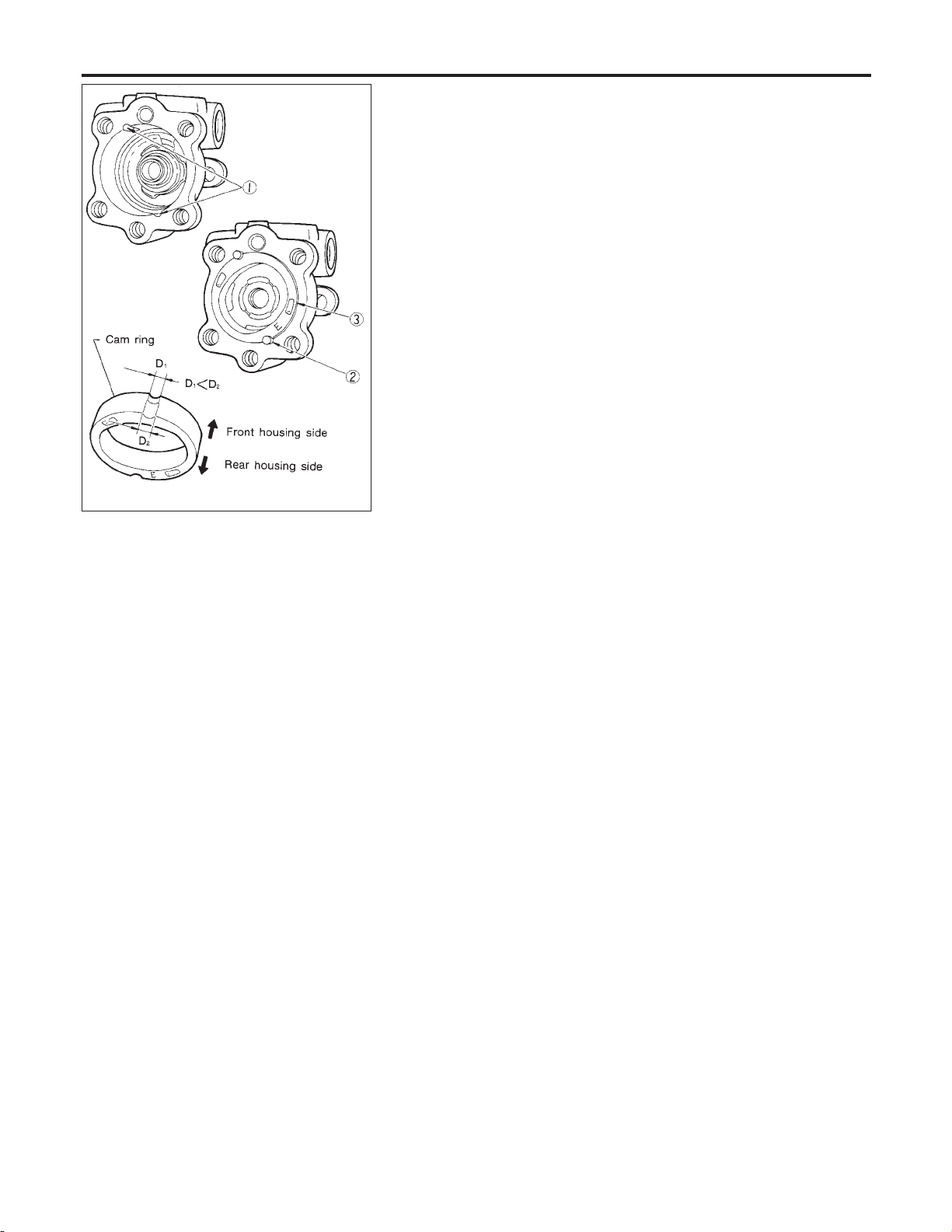
Assembly (Cont’d)
POWER STEERING OIL PUMP
! Insert pin 2 into pin groove 1 of front housing and front side
plate. Then install cam ring 3 as shown at left.
Cam ring:
D1is less than D2.
SST472C
ST-28
Page 62

SERVICE DATA AND SPECIFICATIONS (SDS)
General Specifications
General Specifications
Power steering
Steering model
15 or 16 inch tire 17 inch tire
Steering gear type PR26AD
Steering overall gear ratio 16.6
Turns of steering wheel (Lock to lock) 2.9 2.6
Steering column type Collapsible, tilt
Steering Wheel
Steering wheel axial play mm (in) 0 (0)
Steering wheel play mm (in) 35 (1.38) or less
Movement of gear housing mm (in) ±2(±0.08) or less
Steering Column
Applied model All
Steering column length “L” mm (in) 542 - 544 (21.34 - 21.42)
NHST0032
NHST0033
NHST0034
GI
MA
EM
LC
EC
FE
AT
AX
SST855C
SU
BR
RS
BT
HA
SC
EL
IDX
ST-29
Page 63

Steering Gear and Linkage
SERVICE DATA AND SPECIFICATIONS (SDS)
Steering Gear and Linkage
Applied model All
Steering gear type PR26AD
Swinging force at cotter pin hole: “A” N (kg, lb) 6.5 - 65.7 (0.66 - 6.59, 1.5 - 14.8)
Tie-rod outer ball joint
Tie-rod inner ball joint
Tie-rod standard length “L” mm (in) 193.2 (7.606)
*: Measuring point [!: 172 mm (6.77 in)]
Rotating torque: “B” N·m (kg-cm, in-lb) 0.29 - 2.94 (3.0 - 30.0, 2.6 - 26.0)
Axial end play: “C” mm (in) 0.4 (0.016) or less
Swinging force*: “A” N (kg, lb) 5.7 - 45.6 (0.58 - 4.65, 1.3 - 10.3)
Axial end play: “C” mm (in) 0.2 (0.008) or less
NHST0035
SST867C
Initial tightening torque N·m (kg-cm, in-lb) 4.9 - 5.9 (50 - 60, 43 - 52)
Retightening torque after loosening N·m (kg-cm,
Retainer adjustment
Adjusting screw
Steering gear type PR26AD
Rack stroke “S” mm (in) 70.5 (2.776)
in-lb)
Tightening torque after gear has settled N·m
(kg-cm, in-lb)
Returning angle degree 60° - 80°
0.2 (2, 1.7)
4.9 - 5.9 (50 - 60, 43 - 52)
SST086BA
ST-30
Page 64

SERVICE DATA AND SPECIFICATIONS (SDS)
Power Steering
Power Steering
Applied model All
Steering gear type PR26AD
Range within ±11.5 mm (±0.453 in)
Rack sliding force N (kg, lb)
Under normal operating oil pressure
Steering wheel turning force
(Measured at one full turn from the neutral position) N (kg, lb)
Fluid capacity (Approximate) ! (US qt, Imp qt) 1.0 (1-1/8, 7/8)
Oil pump maximum pressure kPa (kg/cm
from the neutral position at rack
speed of 3.5 mm (0.138 in)/s
Except for the above range
2
, psi)
Average force 216 - 284 (22 - 29, 49 - 64)
Maximum force deviation 98 (10, 22)
Maximum sliding force 294 (30, 66)
Maximum force deviation 147 (15, 33)
39 (4, 9) or less
8,140 - 8,728 (83 - 89, 1,180 -
1,266)
NHST0036
GI
MA
EM
LC
EC
FE
AT
AX
SU
BR
RS
BT
HA
SC
EL
IDX
ST-31
Page 65

NOTES
Page 66

STARTING & CHARGING SYSTEM
GI
MA
CONTENTS
PRECAUTIONS ...............................................................2
Supplemental Restraint System (SRS) ″AIR
BAG″ and ″SEAT BELT PRE-TENSIONER″...............2
Wiring Diagrams and Trouble Diagnosis .....................2
BATTERY.........................................................................3
How to Handle Battery ................................................3
METHODS OF PREVENTING OVER-DISCHARGE
CHECKING ELECTROLYTE LEVEL
SPECIFIC GRAVITY CHECK
CHARGING THE BATTERY
STARTING SYSTEM .......................................................6
System Description......................................................6
Wiring Diagram - START -...........................................7
Construction.................................................................8
Removal and Installation .............................................8
REMOVAL
.................................................................8
........................................5
............................3
......................................4
......3
SECTION
INSTALLATION
Pinion/Clutch Check ....................................................9
CHARGING SYSTEM ....................................................10
System Description....................................................10
Wiring Diagram - CHARGE -..................................... 11
Trouble Diagnoses.....................................................12
WITH IC REGULATOR
MALFUNCTION INDICATOR
Construction...............................................................13
Removal and Installation ...........................................13
REMOVAL
INSTALLATION
SERVICE DATA AND SPECIFICATIONS (SDS) .........14
Battery........................................................................14
Starter ........................................................................14
Alternator ...................................................................14
..........................................................8
...............................................................13
........................................................13
SC
.............................................12
....................................12
EM
LC
EC
FE
AT
AX
SU
BR
ST
RS
BT
HA
EL
IDX
Page 67

PRECAUTIONS
Supplemental Restraint System (SRS) “AIR BAG” and “SEAT BELT PRE-TENSIONER”
Supplemental Restraint System (SRS) “AIR
BAG” and “SEAT BELT PRE-TENSIONER”
The Supplemental Restraint System such as “AIR BAG” and “SEAT BELT PRE-TENSIONER” used along with
a seat belt, helps to reduce the risk or severity of injury to the driver and front passenger for certain types of
collision. The SRS system composition which is available to INFINITI I30 is as follows:
! For a frontal collision
The Supplemental Restraint System consists of driver air bag module (located in the center of the steering wheel), front passenger air bag module (located on the instrument panel on passenger side), seat belt
pre-tensioners, a diagnosis sensor unit, warning lamp, wiring harness and spiral cable.
! For a side collision
The Supplemental Restraint System consists of front side air bag module (located in the outer side of front
seat), satellite sensor, diagnosis sensor unit (one of components of air bags for a frontal collision), wiring
harness, warning lamp (one of components of air bags for a frontal collision).
Information necessary to service the system safely is included in the RS section of this Service Manual.
WARNING:
! To avoid rendering the SRS inoperative, which could increase the risk of personal injury or death
in the event of a collision which would result in air bag inflation, all maintenance should be performed by an authorized INFINITI dealer.
! Improper maintenance, including incorrect removal and installation of the SRS, can lead to per-
sonal injury caused by unintentional activation of the system. For removal of Spiral Cable and Air
Bag Module, see the RS section.
! Do not use electrical test equipment on any circuit related to the SRS unless instructed to in this
Service Manual. Spiral cable and wiring harnesses covered with yellow insulation tape either just
before the harness connectors or for the complete harness are related to the SRS.
NHSC0001
Wiring Diagrams and Trouble Diagnosis
When you read wiring diagrams, refer to the following:
! GI-9, “HOW TO READ WIRING DIAGRAMS”
! EL-10, “POWER SUPPLY ROUTING” for power distribution circuit
When you perform trouble diagnosis, refer to the following:
! GI-36, “HOW TO FOLLOW TEST GROUPS IN TROUBLE DIAGNOSES”
! GI-25, “HOW TO PERFORM EFFICIENT DIAGNOSIS FOR AN ELECTRICAL INCIDENT”
NHSC0002
SC-2
Page 68

BATTERY
How to Handle Battery
MEL040F
How to Handle Battery
CAUTION:
! If it becomes necessary to start the engine with a booster
battery and jumper cables, use a 12-volt booster battery.
! After connecting battery cables, ensure that they are
tightly clamped to battery terminals for good contact.
! Never add distilled water through the hole used to check
specific gravity.
METHODS OF PREVENTING OVER-DISCHARGE
The following precautions must be taken to prevent over-discharging a battery.
! The battery surface (particularly its top) should always be kept
clean and dry.
! The terminal connections should be clean and tight.
! At every routine maintenance, check the electrolyte level.
This also applies to batteries designated as “low maintenance”
and “maintenance-free”.
! When the vehicle is not going to be used over a long period of
time, disconnect the negative battery terminal. (If the vehicle
has an extended storage switch, turn it off.)
NHSC0003
NHSC0003S01
GI
MA
EM
LC
EC
FE
AT
AX
SU
MEL041F
MEL042F
! Check the charge condition of the battery.
Periodically check the specific gravity of the electrolyte. Keep
a close check on charge condition to prevent over-discharge.
CHECKING ELECTROLYTE LEVEL
WARNING:
Do not allow battery fluid to come in contact with skin, eyes,
fabrics, or painted surfaces. After touching a battery, do not
touch or rub your eyes until you have thoroughly washed your
hands. If acid contacts eyes, skin or clothing, immediately
flush with water for 15 minutes and seek medical attention.
NHSC0003S02
BR
ST
RS
BT
HA
EL
IDX
SC-3
Page 69
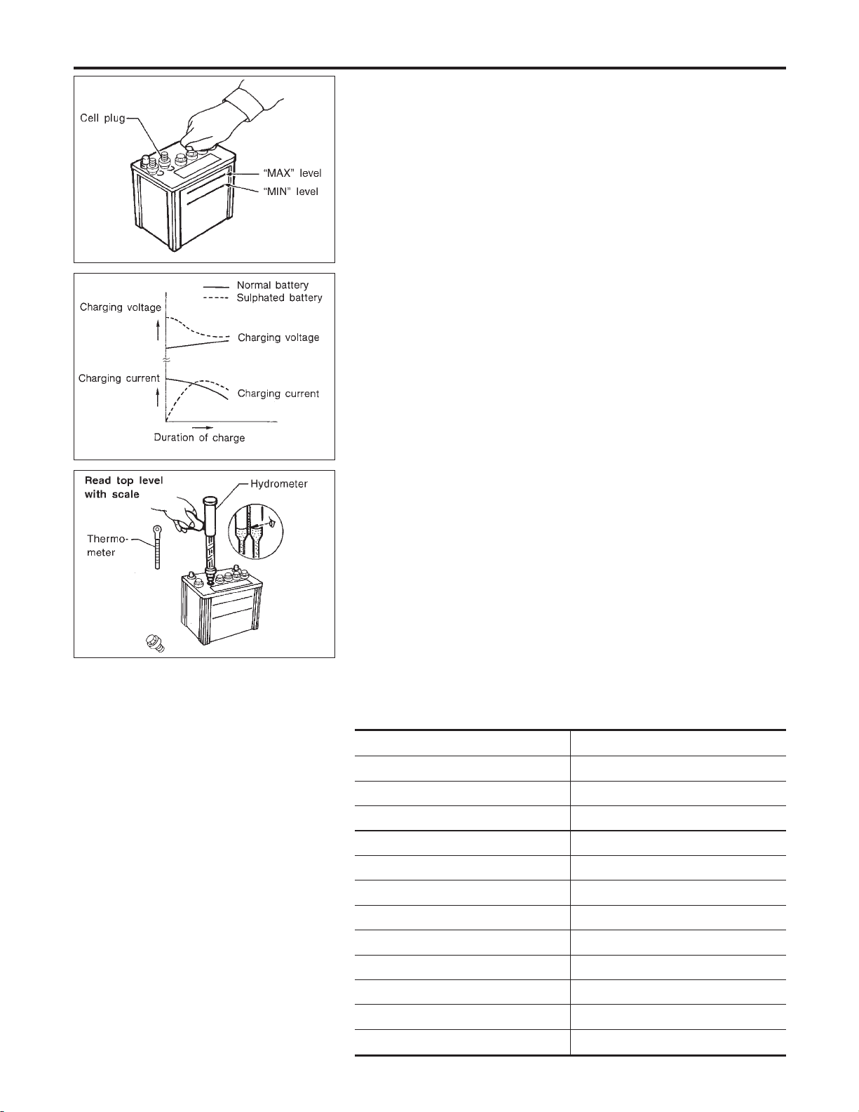
How to Handle Battery (Cont’d)
MEL043F
SEL709E
BATTERY
! Remove the cell plug using a suitable tool.
! Add distilled water up to the MAX level.
Sulphation
A battery will be completely discharged if it is left unattended
for a long time and the specific gravity will become less than
1.100. This may result in sulphation on the cell plates.
To determine if a battery has been “sulphated”, note its voltage and current when charging it. As shown in the figure, less
current and higher voltage are observed in the initial stage of
charging sulphated batteries.
A sulphated battery may sometimes be brought back into service by means of a long, slow charge, 12 hours or more, followed by a battery capacity test.
SPECIFIC GRAVITY CHECK
1. Read hydrometer and thermometer indications at eye level.
NHSC0003S0201
NHSC0003S03
MEL042FA
2. Use the chart below to correct your hydrometer reading
according to electrolyte temperature.
Hydrometer Temperature Correction
Battery electrolyte temperature °C (°F) Add to specific gravity reading
71 (160) 0.032
66 (150) 0.028
60 (140) 0.024
54 (130) 0.020
49 (120) 0.016
43 (110) 0.012
38 (100) 0.008
32 (90) 0.004
27 (80) 0
21 (70) −0.004
16 (60) −0.008
10 (50) −0.012
NHSC0003S0301
SC-4
Page 70

BATTERY
How to Handle Battery (Cont’d)
Battery electrolyte temperature °C (°F) Add to specific gravity reading
4 (40) −0.016
−1 (30) −0.020
−7 (20) −0.024
−12 (10) −0.028
−18 (0) −0.032
Corrected specific gravity Approximate charge condition
1.260 - 1.280 Fully charged
1.230 - 1.250 3/4 charged
1.200 - 1.220 1/2 charged
1.170 - 1.190 1/4 charged
1.140 - 1.160 Almost discharged
1.110 - 1.130 Completely discharged
CHARGING THE BATTERY
NHSC0003S04
CAUTION:
! Do not “quick charge” a fully discharged battery.
! Keep the battery away from open flame while it is being
charged.
! When connecting the charger, connect the leads first, then
turn on the charger. Do not turn on the charger first, as
this may cause a spark.
! If battery electrolyte temperature rises above 60°C (140°F),
stop charging. Always charge battery at a temperature
below 60°C (140°F).
Charging Rates
Amps Time
NHSC0003S0401
GI
MA
EM
LC
EC
FE
AT
AX
SU
BR
ST
RS
50 1 hour
25 2 hours
10 5 hours
5 10 hours
Do not charge at more than 50 ampere rate.
NOTE:
The ammeter reading on your battery charger will automatically
decrease as the battery charges. This indicates that the voltage of
the battery is increasing normally as the state of charge improves.
The charging amps indicated above refer to initial charge rate.
! If, after charging, the specific gravity of any two cells varies
more than .050, the battery should be replaced.
SC-5
BT
HA
EL
IDX
Page 71

System Description
STARTING SYSTEM
System Description
Power is supplied at all times
! through 40A fusible link (letter c, located in the fuse and fusible link box)
! to ignition switch terminal 1.
With the ignition switch in the ON or START position, power is supplied
! through 15A fuse [No. 20, located in the fuse block (J/B)]
! to park/neutral position relay terminal 1.
Also, with the ignition switch in the START position, power is supplied
! from ignition switch terminal 5
! to park/neutral position relay terminal 6.
Ground is supplied, with the selector lever in the P or N position
! to park/neutral position relay terminal 2
! through park/neutral position switch.
The park/neutral position relay is energized and power is supplied
! from ignition switch terminal 5
! through park/neutral position relay terminals 6 and 7
! to terminal 2 of the starter motor windings.
The starter motor plunger closes and provides a closed circuit between the battery and the starter motor. The
starter motor is grounded to the cylinder block. With power and ground supplied, the starter motor operates.
NHSC0004
SC-6
Page 72

STARTING SYSTEM
Wiring Diagram — START —
Wiring Diagram — START —
NHSC0005
GI
MA
EM
LC
EC
FE
AT
AX
SU
BR
ST
RS
BT
HA
EL
IDX
SC-7
MEL393K
Page 73

Construction
STARTING SYSTEM
Construction
NHSC0006
SEL457T
Removal and Installation
REMOVAL
1. Remove air duct assembly.
2. Remove harness protector from engine room harness.
3. Disconnect starter harness.
4. Remove starter bolts (two).
5. Remove starter.
INSTALLATION
To install, reverse the removal procedure.
SEL456TF
NHSC0007
NHSC0007S01
NHSC0007S02
SEL458T
SC-8
Page 74

STARTING SYSTEM
Pinion/Clutch Check
Pinion/Clutch Check
1. Inspect pinion teeth.
! Replace pinion if teeth are worn or damaged. (Also check
condition of ring gear teeth.)
2. Inspect reduction gear teeth.
! Replace reduction gear if teeth are worn or damaged. (Also
check condition of armature shaft gear teeth.)
3. Check to see if pinion locks in one direction and rotates
smoothly in the opposite direction.
! If it locks or rotates in both directions, or unusual resistance is
evident, replace.
NHSC0008
GI
MA
EM
LC
EC
FE
AT
AX
SU
BR
ST
RS
BT
HA
EL
IDX
SC-9
Page 75

System Description
CHARGING SYSTEM
System Description
The alternator provides DC voltage to operate the vehicle’s electrical system and to keep the battery charged.
The voltage output is controlled by the IC regulator.
Power is supplied at all times to alternator terminal 3 (S) through:
! 120A fusible link (letter a, located in the fuse and fusible link box), and
! 10A fuse (No. 70, located in the fuse and fusible link box).
Terminal B supplies power to charge the battery and operate the vehicle’s electrical system. Output voltage
is controlled by the IC regulator at terminal 3 (S) detecting the input voltage. The charging circuit is protected
by the 120A fusible link.
The alternator is grounded to the engine block.
With the ignition switch in the ON or START position, power is supplied
! through 10A fuse [No. 30, located in the fuse block (J/B)]
! to combination meter terminal 66 for the charge warning lamp.
Ground is supplied to terminal 68 of the combination meter through terminal 2 (L) of the alternator. With power
and ground supplied, the charge warning lamp will illuminate. When the alternator is providing sufficient voltage with the engine running, the ground is opened and the charge warning lamp will go off.
If the charge warning lamp illuminates with the engine running, a fault is indicated.
NHSC0009
SC-10
Page 76

CHARGING SYSTEM
Wiring Diagram — CHARGE —
Wiring Diagram — CHARGE —
NHSC0010
GI
MA
EM
LC
EC
FE
AT
AX
SU
BR
ST
RS
BT
HA
EL
IDX
SC-11
MEL210K
Page 77

Trouble Diagnoses
CHARGING SYSTEM
Trouble Diagnoses
NHSC0011
Before conducting an alternator test, make sure that the battery is fully charged. A 30-volt voltmeter and suitable test probes are necessary for the test. The alternator can be checked easily by referring to the Inspection Table.
! Before starting, inspect the fusible link.
! Use fully charged battery.
WITH IC REGULATOR
NHSC0011S01
SEL338V
NOTE:
! If the inspection result is OK even though the charging system is malfunctioning, check the B terminal
connection. (Check the tightening torque.)
! When field circuit is open, check condition of rotor coil, rotor slip ring and brush. If necessary, replace faulty
parts with new ones.
MALFUNCTION INDICATOR
NHSC0011S02
The IC regulator warning function activates to illuminate “CHARGE” warning lamp, if any of the following
symptoms occur while alternator is operating:
! Excessive voltage is produced.
! No voltage is produced.
SC-12
Page 78

CHARGING SYSTEM
Construction
Construction
NHSC0012
GI
MA
EM
LC
EC
FE
AT
AX
SEL460T
Removal and Installation
REMOVAL
1. Remove engine undercover RH.
2. Remove side inspection cover RH.
3. Loosen belt idler pulley.
4. Remove drive belt.
5. Remove A/C compressor mounting bolts (four).
6. Slide A/C compressor forward.
7. Disconnect alternator harness connector.
8. Remove alternator upper bolt and lower bolt.
INSTALLATION
To install, reverse the removal procedure.
SEL276VI
NHSC0013
NHSC0013S01
NHSC0013S02
SU
BR
ST
RS
BT
HA
EL
IDX
MEL384KA
SC-13
Page 79

Battery
SERVICE DATA AND SPECIFICATIONS (SDS)
Battery
Type 80D26L
Capacity V-AH 12-55
Cold cranking current A
(For reference value)
582
Starter
S114-801D
Type
System voltage 12V
Terminal voltage 11.0V
No-load
Minimum diameter of commutator 28.0 mm (1.102 in)
Minimum length of brush 10.5 mm (0.413 in)
Brush spring tension 12.7 - 17.7 N (1.3 - 1.8 kg, 2.9 - 4.0 lb)
Clearance between pinion front edge and pinion stopper 0.3 - 2.5 mm (0.012 - 0.098 in)
Current Less than 90A
Revolution More than 2,700 rpm
HITACHI make
Reduction gear type
NHSC0014
NHSC0015
Alternator
Type
Nominal rating 12V-110A
Ground polarity Negative
Minimum revolution under no-load (When 13.5 volts is applied) Less than 950 rpm
Hot output current (When 13.5 volts is applied)
Regulated output voltage 14.1 - 14.7V
Minimum length of brush More than 6.00 mm (0.2362 in)
Brush spring pressure 1.000 - 3.432 N (102 - 350 g, 3.60 - 12.34 oz)
Slip ring minimum outer diameter More than 26.0 mm (1.024 in)
Rotor (Field coil) resistance 2.31Ω
LR1100-725C
HITACHI make
More than 33A/1,300 rpm
More than 81A/2,500 rpm
More than 93A/5,000 rpm
NHSC0016
SC-14
Page 80

RESTRAINT SYSTEM
GI
MA
CONTENTS
SEAT BELTS ...................................................................3
Precautions ..................................................................3
SUPPLEMENTAL RESTRAINT SYSTEM (SRS)
″AIR BAG″ AND ″SEAT BELT PRE-TENSIONER″
PRECAUTION FOR SEAT BELT SERVICE
Front Seat Belt.............................................................5
REMOVAL AND INSTALLATION
Rear Seat Belt .............................................................7
REMOVAL AND INSTALLATION
Seat Belt Inspection.....................................................9
AFTER A COLLISION
PRELIMINARY CHECKS
SEAT BELT RETRACTOR ON-VEHICLE CHECK
SEAT BELT RETRACTOR OFF-VEHICLE CHECK
Tether Anchor Plate ...................................................12
REMOVAL AND INSTALLATION
SUPPLEMENTAL RESTRAINT SYSTEM (SRS) .........13
Precautions ................................................................13
SUPPLEMENTAL RESTRAINT SYSTEM (SRS)
″AIR BAG″ AND ″SEAT BELT PRE-TENSIONER″
PRECAUTIONS FOR SRS ″AIR BAG″ AND ″SEAT
BELT PRE-TENSIONER″ SERVICE
WIRING DIAGRAMS AND TROUBLE DIAGNOSIS
Preparation ................................................................14
SPECIAL SERVICE TOOLS
COMMERCIAL SERVICE TOOL
SRS Configuration ..................................................... 15
Seat Belt Pre-tensioner with Load Limiter.................16
Built-in Type Side Air Bag..........................................16
SRS Component Parts Location ...............................17
Maintenance Items ....................................................17
Diagnosis Sensor Unit ...............................................18
REMOVAL AND INSTALLATION
Seat Belt Pre-tensioner .............................................19
REMOVAL AND INSTALLATION
Satellite Sensor..........................................................19
REMOVAL AND INSTALLATION
Driver Air Bag Module and Spiral Cable ...................20
REMOVAL AND INSTALLATION
REMOVAL
...............................................................20
.................................................9
.................................5
.................................7
............................................9
...............................12
...........................13
......................................14
................................15
...............................18
...............................19
...............................19
...............................20
........3
..................3
.......10
.....10
......13
.....13
SECTION
INSTALLATION
Front Passenger Air Bag Module ..............................22
REMOVAL
INSTALLATION
Side Air Bag Module..................................................24
REMOVAL
INSTALLATION
Disposal of Air Bag Module and Seat Belt Pre-
tensioner ....................................................................25
CHECKING DEPLOYMENT TOOL
DEPLOYMENT PROCEDURES FOR AIR BAG
MODULE (OUTSIDE OF VEHICLE)
DEPLOYMENT PROCEDURES FOR SEAT BELT
PRE-TENSIONER (OUTSIDE OF VEHICLE)
DEPLOYMENT OF AIR BAG MODULE AND SEAT
BELT PRE-TENSIONER WHILE MOUNTED IN
VEHICLE
DISPOSING OF AIR BAG MODULE AND SEAT
BELT PRE-TENSIONER
Trouble Diagnoses Introduction.................................32
DIAGNOSIS FUNCTION
DIAGNOSIS MODE FOR CONSULT-II
HOW TO CHANGE SELF-DIAGNOSIS MODE
WITH CONSULT-II
HOW TO CHANGE SELF-DIAGNOSIS MODE
WITHOUT CONSULT-II
HOW TO ERASE SELF-DIAGNOSIS RESULTS
How to Perform Trouble Diagnoses for Quick
and Accurate Repair ..................................................35
INFORMATION FROM CUSTOMER
PRELIMINARY CHECK
WORK FLOW
Schematic ..................................................................37
Wiring Diagram - SRS -.............................................38
SRS Operation Check ...............................................41
DIAGNOSTIC PROCEDURE 1
Trouble Diagnoses with CONSULT-II...................42
DIAGNOSTIC PROCEDURE 2
DIAGNOSTIC PROCEDURE 3
DIAGNOSTIC PROCEDURE 4 (CONTINUED
FROM DIAGNOSTIC PROCEDURE 2)
........................................................22
...............................................................22
........................................................23
...............................................................24
........................................................25
.................................................................30
..........................................................36
RS
.............................26
...........................27
..............29
...........................................30
...........................................32
.......................32
...................................................33
............................................33
.........33
..........................35
............................................35
..................................41
..................................42
..................................45
......................47
EM
LC
EC
FE
AT
AX
SU
BR
ST
BT
HA
SC
EL
IDX
Page 81

CONTENTS (Cont’d)
DIAGNOSTIC PROCEDURE 5
Trouble Diagnoses without CONSULT-II..............51
DIAGNOSTIC PROCEDURE 6
DIAGNOSTIC PROCEDURE 7
DIAGNOSTIC PROCEDURE 8 (CONTINUED
FROM DIAGNOSTIC PROCEDURE 6)
Trouble Diagnoses: ″AIR BAG″ Warning Lamp
Does Not Turn Off .....................................................59
..................................47
..................................51
..................................56
......................58
DIAGNOSTIC PROCEDURE 9
Trouble Diagnoses: ″AIR BAG″ Warning Lamp
Does Not Turn On .....................................................61
DIAGNOSTIC PROCEDURE 10
Collision Diagnosis ....................................................62
FOR FRONTAL COLLISION
FOR SIDE COLLISION
..................................59
................................61
.....................................62
.............................................64
RS-2
Page 82

SEAT BELTS
Precautions
Precautions
SUPPLEMENTAL RESTRAINT SYSTEM (SRS) “AIR BAG” AND “SEAT BELT
PRE-TENSIONER”
The Supplemental Restraint System such as “AIR BAG” and “SEAT BELT PRE-TENSIONER” used along with
a seat belt, helps to reduce the risk or severity of injury to the driver and front passenger for certain types of
collision. The SRS composition which is available to INFINITI I30 is as follows:
! For a frontal collision
The Supplemental Restraint System consists of driver air bag module (located in the center of the steering wheel), front passenger air bag module (located on the instrument panel on passenger side), seat belt
pre-tensioners, a diagnosis sensor unit, warning lamp, wiring harness and spiral cable.
! For a side collision
The Supplemental Restraint System consists of front side air bag module (located in the outer side of front
seat), satellite sensor, diagnosis sensor unit (one of components of air bags for a frontal collision), wiring
harness, warning lamp (one of components of air bags for a frontal collision).
WARNING:
! To avoid rendering the SRS inoperative, which could increase the risk of personal injury or death
in the event of a collision which would result in air bag inflation, all maintenance should be performed by an authorized INFINITI dealer.
! Improper maintenance, including incorrect removal and installation of the SRS, can lead to per-
sonal injury caused by unintentional activation of the system.
! Do not use electrical test equipment on any circuit related to the SRS unless instructed to in this
Service Manual. Spiral cable and wiring harnesses covered with yellow insulation tape either just
before the harness connectors or for the complete harness are related to the SRS.
PRECAUTION FOR SEAT BELT SERVICE
CAUTION:
! Before removing the seat belt pre-tensioner assembly, turn the ignition switch off, disconnect both
battery cables and wait at least 3 minutes.
! Do not use electrical test equipment for seat belt pre-tensioner connector.
! After replacing or reinstalling seat belt pre-tensioner assembly, or reconnecting seat belt pre-ten-
sioner connector, check the system function.
Refer to “SRS Operation Check” for details. (RS-41)
! Do not use disassemble buckle or seat belt assembly.
! Replace anchor bolts if they are deformed or worn out.
! Never oil tongue and buckle.
! If any component of seat belt assembly is questionable, do not repair. Replace the whole seat belt
assembly.
! If webbing is cut, frayed, or damaged, replace seat belt assembly.
! When replacing seat belt assembly, use a genuine seat belt assembly.
After A Collision
WARNING:
Inspect all seat belt assemblies including retractors and attaching hardware after any collision.
NISSAN recommends that all seat belt assemblies in use during a collision be replaced unless the
collision was minor and the belts show no damage and continue to operate properly. Failure to do so
could result in serious personal injury in an accident. Seat belt assemblies not in use during a collision should also be replaced if either damage or improper operation is noted. Seat belt pre-tensioner
should be replaced even if the seat belts are not in use during a frontal collision in which the air bags
are deployed.
Replace any seat belt assembly if:
! The seat belt was in use at the time of a collision (except for minor collisions and the belts, retractors and
buckles show no damage and continue to operate properly).
! The seat belt was damaged in an accident. (i.e. torn webbing, bent retractor or guide, etc.)
! The seat belt attaching point was damaged in an accident. Inspect the seat belt attaching area for dam-
age or distortion and repair as necessary before installing a new seat belt assembly.
! Anchor bolts are deformed or worn out.
! The seat belt pre-tensioner should be replaced even if the seat belts are not in use during the collision in
NHRS0001
NHRS0002
NHRS0002S01
GI
MA
EM
LC
EC
FE
AT
AX
SU
BR
ST
BT
HA
SC
EL
IDX
RS-3
Page 83

Precautions (Cont’d)
which the air bags are deployed.
SEAT BELTS
RS-4
Page 84

SEAT BELTS
Front Seat Belt
Front Seat Belt
REMOVAL AND INSTALLATION
1. Slide the seat all the way forward and tilt the seatback toward the front.
2. Remove adjuster cover.
3. Slide floor anchor cover.
4. Remove floor anchor bolt.
5. Remove shoulder anchor bolt.
6. Remove front and rear kicking plate, then remove center pillar upper and lower garnish. Refer to BT-32,
“SIDE AND FLOOR TRIM” for details.
7. Disconnect seat belt pre-tensioner connector.
8. Remove the screw securing seat belt pre-tensioner retractor, then remove seat belt and seat belt pre-tensioner retractor.
9. Remove bolts securing seat belt adjuster, then remove seat belt adjuster.
=NHRS0003
GI
MA
EM
LC
EC
FE
AT
SRS714-A
AX
SU
BR
ST
BT
HA
SC
EL
RS-5
IDX
Page 85
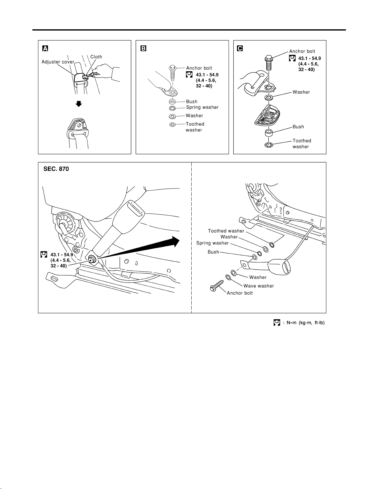
Front Seat Belt (Cont’d)
SEAT BELTS
RS-6
SRS789
Page 86
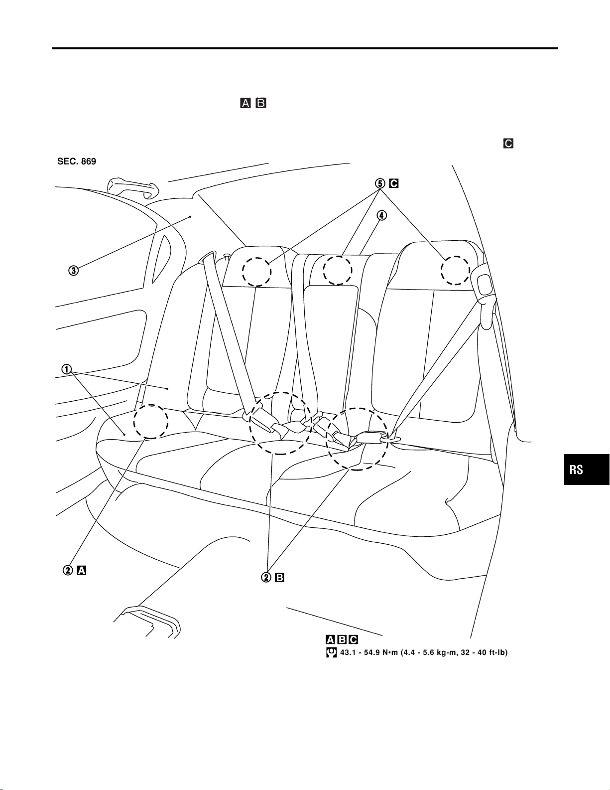
SEAT BELTS
Rear Seat Belt
REMOVAL AND INSTALLATION
1. Remove rear seat. Refer to BT-49, “REAR SEAT” for details.
2. Remove outer and floor anchor bolt.
3. Remove rear side garnish. Refer to BT-32, “SIDE AND FLOOR TRIM” for details.
4. Remove rear parcel shelf finisher. Refer to BT-32, “SIDE AND FLOOR TRIM” for details.
5. Remove bolts securing rear seat belt retractor, then remove seat belt and seat belt retractor.
Rear Seat Belt
=NHRS0004
GI
MA
EM
LC
EC
FE
AT
AX
SU
BR
ST
BT
HA
SC
EL
RS-7
IDX
SRS716-A
Page 87

Rear Seat Belt (Cont’d)
SEAT BELTS
RS-8
SRS717-A
Page 88

SEAT BELTS
Seat Belt Inspection
Seat Belt Inspection
AFTER A COLLISION
WARNING:
Inspect all seat belt assemblies including retractors and attaching hardware after any collision.
NISSAN recommends that all seat belt assemblies in use during a collision be replaced unless the
collision was minor and the belts show no damage and continue to operate properly. Failure to do so
could result in serious personal injury in an accident. Seat belt assemblies not in use during a collision should also be replaced if either damage or improper operation is noted. Seat belt pre-tensioner
should be replaced even if the seat belts are not in use during a frontal collision in which the air bags
are deployed.
Replace any seat belt assembly if:
! The seat belt was in use at the time of a collision (except for minor collisions and the belts, retractors and
buckles show no damage and continue to operate properly).
! The seat belt was damaged in an accident. (i.e. torn webbing, bent retractor or guide, etc.)
! The seat belt attaching point was damaged in an accident. Inspect the seat belt attaching area for dam-
age or distortion and repair as necessary before installing a new seat belt assembly.
! Anchor bolts are deformed or worn out.
! The seat belt pre-tensioner should be replaced even if the seat belts are not in use during the collision in
which the air bags are deployed.
PRELIMINARY CHECKS
1. Check the air bag warning lamp/chime for proper operation as follows:
a. Switch ignition ON. The air bag warning lamp should illuminate. Also, the air bag warning chime should
sound for about seven seconds.
b. Fasten driver’s seat belt. The seat belt warning lamp should go out and the chime (if sounding) should
stop.
c. If the air bag warning lamp is blinking, conduct self-diagnosis using CONSULT-II, and air bag warning lamp.
Refer to “SRS Operation Check”, RS-41.
2. Check that the seat belt retractor, seat belt anchor and buckle bolts are securely attached.
3. Check the shoulder seat belt guide and shoulder belt height adjuster for front seats. Ensure guide swivels freely and that belt lays flat and does not bind in guide. Ensure height adjuster operates properly and
holds securely.
4. Check retractor operation:
a. Fully extend the seat belt webbing and check for twists, tears or other damage.
b. Allow the seat belt to retract. Ensure that belt returns smoothly and completely into the retractor. If the seat
belt does not returns smoothly, wipe the inside of the loops with a clean paper cloth etc. because dirt built
up in the loops of the upper anchors can cause the seat belts to retractor slowly.
c. Fasten the seat belt. Pull firmly on belt and buckle to ensure belt remains latched. Unfasten seat belt.
Ensure belt releases freely and buckle button returns to original position.
=NHRS0052
NHRS0052S01
NHRS0052S02
GI
MA
EM
LC
EC
FE
AT
AX
SU
BR
ST
BT
HA
SRS718
5. Repeat steps above as necessary to check the other seat belts.
RS-9
SC
EL
IDX
Page 89

Seat Belt Inspection (Cont’d)
SEAT BELTS
SEAT BELT RETRACTOR ON-VEHICLE CHECK
Emergency Locking Retractors (ELR) and Automatic Locking Retractors (ALR)
NHRS0052S03
NHRS0052S0301
NOTE:
All seat belt retractors are of the Emergency Locking Retractors (ELR) type. In an emergency (sudden stop)
the retractor will lock and prevent the belt from extending any further. All 3-point type seat belt retractors except
the driver’s seat belt also have an Automatic Locking Retractors (ALR) mode. The ALR mode (also called child
restraint mode) is used when installing child seats. The ALR mode is activated when the seat belt is fully
extended. When the belt is then retracted partially, the ALR mode automatically locks the seat belt in a specific position so the belt cannot be extended any further. To cancel the ALR mode, allow the seat belt to fully
wind back into the retractor.
Check the seat belt retractors using the following test(s) to determine if a retractor assembly is operating
properly.
ELR Function Stationary Check
NHRS0052S0302
Grasp the shoulder belt and pull forward quickly. The retractor should lock and prevent the belt from extending further.
ALR Function Stationary Check
NHRS0052S0303
1. Pull out entire length of seat belt from retractor until a click is heard.
2. Retract the belt partially. A clicking noise should be heard as the belt retracts indicating that the retractor
is in the Automatic Locking Retractors (ALR) mode.
3. Grasp the seat belt and try to pull out the retractor. The belt must lock and not extend any further. If NG,
replace the retractor assembly.
4. Allow the entire length of the belt to retract to cancel the automatic locking mode.
ELR Function Moving Check
NHRS0052S0304
WARNING:
Perform the following test in a safe, open area clear of other vehicles and obstructions (for example,
a large, empty parking lot). Road surface must be paved and dry. DO NOT perform the following test
on wet or gravel roads or on public streets and highways. This could result in an accident and serious personal injury. The driver and passenger must be prepared to brace themselves in the event the
retractor does not lock.
1. Fasten driver’s seat belt. Buckle a passenger into the seat for the belt that is to be tested.
2. Proceed to the designated safe area.
3. Drive the vehicle at approximately 16 km/h (10 MPH). Notify any passengers of a pending sudden stop
and the driver and passenger must be prepared to brace themselves in the event the retractor does not
lock, apply brakes firmly and make a very hard stop.
During stop, seat belts should lock and not be extended. If the seat belt retractor assembly does not lock,
perform the retractor off-vehicle check.
SEAT BELT RETRACTOR OFF-VEHICLE CHECK
NHRS0052S04
1. Remove the seat belt retractor assembly.
2. Slowly pull out belt while tilting the retractor assembly forward from the mounted position without twisting
the retractor assembly as shown in the illustration.
15 degrees or less tilt: Belt can be pulled out.
35 degrees or more tilt: Belt locks and cannot be pulled out.
RS-10
Page 90
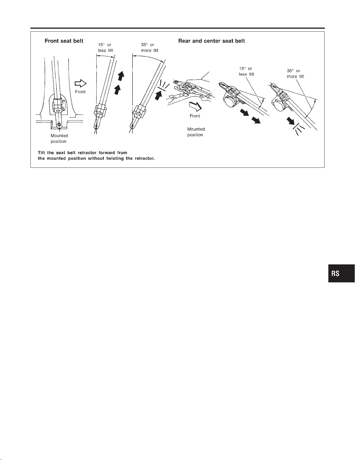
SEAT BELTS
Seat Belt Inspection (Cont’d)
GI
MA
EM
LC
EC
FE
SRS404-A
If NG, replace the retractor assembly.
AT
AX
SU
BR
ST
BT
HA
SC
RS-11
EL
IDX
Page 91

SEAT BELTS
Tether Anchor Plate
Tether Anchor Plate
REMOVAL AND INSTALLATION
CAUTION:
Replace anchor bolts if they are deformed or worn out.
=NHRS0039
1. Remove tether anchor plate cover. Refer to BT-32, “SIDE AND FLOOR TRIM” for details.
2. Remove tether anchor plate.
NOTE:
! To install, reverse the removal procedure sequence.
SRS719
RS-12
Page 92

SUPPLEMENTAL RESTRAINT SYSTEM (SRS)
Precautions
Precautions
SUPPLEMENTAL RESTRAINT SYSTEM (SRS) “AIR BAG” AND “SEAT BELT
PRE-TENSIONER”
The Supplemental Restraint System such as “AIR BAG” and “SEAT BELT PRE-TENSIONER” used along with
a seat belt, helps to reduce the risk or severity of injury to the driver and front passenger for certain types of
collision. The SRS composition which is available to INFINITI I30 is as follows:
! For a frontal collision
The Supplemental Restraint System consists of driver air bag module (located in the center of the steering wheel), front passenger air bag module (located on the instrument panel on passenger side), seat belt
pre-tensioners, a diagnosis sensor unit, warning lamp, wiring harness and spiral cable.
! For a side collision
The Supplemental Restraint System consists of front side air bag module (located in the outer side of front
seat), satellite sensor, diagnosis sensor unit (one of components of air bags for a frontal collision), wiring
harness, warning lamp (one of components of air bags for a frontal collision).
WARNING:
! To avoid rendering the SRS inoperative, which could increase the risk of personal injury or death
in the event of a collision which would result in air bag inflation, all maintenance should be performed by an authorized INFINITI dealer.
! Improper maintenance, including incorrect removal and installation of the SRS, can lead to per-
sonal injury caused by unintentional activation of the system.
! Do not use electrical test equipment on any circuit related to the SRS unless instructed to in this
Service Manual. Spiral cable and wiring harnesses covered with yellow insulation tape either just
before the harness connectors or for the complete harness are related to the SRS.
PRECAUTIONS FOR SRS “AIR BAG” AND “SEAT BELT PRE-TENSIONER” SERVICE
! Do not use electrical test equipment to check SRS circuits unless instructed to in this Service Manual.
! Before servicing the SRS, turn ignition switch “OFF”, disconnect both battery cables and wait at least 3
minutes.
For approximately 3 minutes after the cables are removed, it is still possible for the air bag and seat belt
pre-tensioner to deploy. Therefore, do not work on any SRS connectors or wires until at least 3 minutes
have passed.
! Diagnosis sensor unit must always be installed with their arrow marks “g” pointing towards the front of
the vehicle for proper operation. Also check diagnosis sensor unit for cracks, deformities or rust before
installation and replace as required.
! The spiral cable must be aligned with the neutral position since its rotations are limited. Do not attempt to
turn steering wheel or column after removal of steering gear.
! Handle air bag module carefully. Always place driver and passenger air bag modules with the pad side
facing upward and place side air bag module (built-in type) standing with stud bolt side setting bottom.
! Conduct self-diagnosis to check entire SRS for proper function after replacing any components.
! After air bag inflates, the front instrument panel assembly should be replaced if damaged.
WIRING DIAGRAMS AND TROUBLE DIAGNOSIS
When you read wiring diagrams, refer to the following:
! GI-11, “HOW TO READ WIRING DIAGRAMS”
! EL-10, “POWER SUPPLY ROUTING” for power distribution circuit
When you perform trouble diagnosis, refer to the following:
! GI-36, “HOW TO FOLLOW TEST GROUP IN TROUBLE DIAGNOSES”
! GI-25, “HOW TO PERFORM EFFICIENT DIAGNOSIS FOR AN ELECTRICAL INCIDENT”
NHRS0006
NHRS0007
NHRS0008
GI
MA
EM
LC
EC
FE
AT
AX
SU
BR
ST
BT
HA
SC
EL
IDX
RS-13
Page 93

SUPPLEMENTAL RESTRAINT SYSTEM (SRS)
Preparation
Preparation
SPECIAL SERVICE TOOLS
The actual shapes of Kent-Moore tools may differ from those of special service tools illustrated here.
Tool number
(Kent-Moore No.)
Tool name
Description
=NHRS0009
KV99106400
(J38381)
Deployment tool
KV99105300
(J41246)
Air bag module bracket
HT61961000 and
HT62152000 combined
(J38219)
*Special torx bit
KV99108300
(J38381-35)
Deployment tool adapter for passenger air bag
Disposing of air bag module
NT357
Anchoring air bag module
NT354
Use for special bolts [TAMPER RESISTANT TORX (Size T50)]
a: 3.5 (0.138) dia.
b: 8.5 - 8.6 (0.335 - 0.339) dia.
c: approx. 10 (0.39) sq.
Unit: mm (in)
NT361
NT775
KV99108200
(J38381-50)
Deployment tool adapter for seat
belt pre-tensioner
NT721
KV99109000
(J44230)
Deployment tool adapters for
built-in type side air bag
NT767
*: Special tool or commercial equivalent
RS-14
Page 94
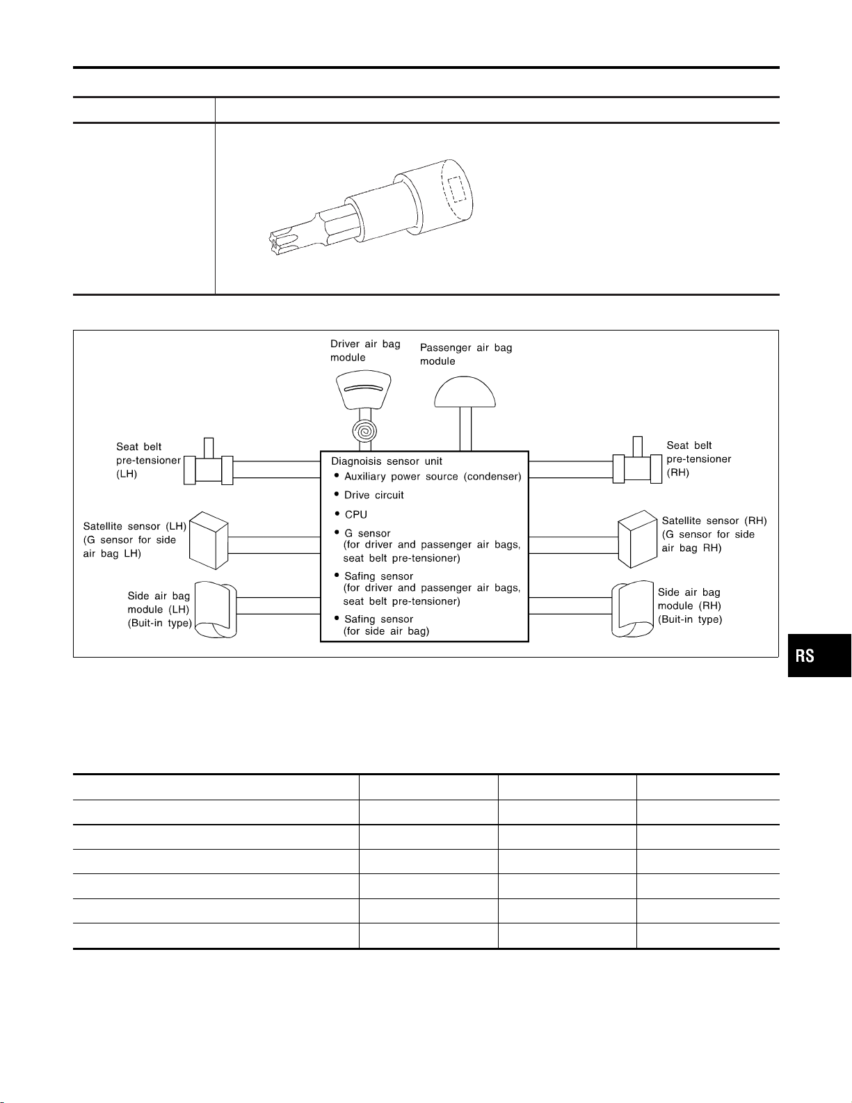
SUPPLEMENTAL RESTRAINT SYSTEM (SRS)
Preparation (Cont’d)
COMMERCIAL SERVICE TOOL
Tool name Description
Tamper resistant torx
socket
NT757
Size: T30
SRS Configuration
NHRS0040
NHRS0010
GI
MA
EM
LC
EC
FE
AT
AX
SU
BR
ST
SRS585-B
The air bag deploys if the diagnosis sensor unit activates while the ignition switch is in the “ON” or “START”
position.
The collision modes for which supplemental restraint systems are activated are different among the SRS systems. For example, the driver air bag module and passenger air bag module are activated in a frontal collision but not in a side collision.
SRS configurations which are activated for some collision modes are as follows;
SRS configuration Frontal collision Left side collision Right side collision
Driver air bag module " ——
Passenger air bag module " ——
Seat belt pre-tensioner (LH) " ——
Seat belt pre-tensioner (RH) " ——
Side air bag module (LH) — " —
BT
HA
SC
EL
IDX
Side air bag module (RH) — — "
RS-15
Page 95

SUPPLEMENTAL RESTRAINT SYSTEM (SRS)
Seat Belt Pre-tensioner with Load Limiter
SRS444
Seat Belt Pre-tensioner with Load Limiter
=NHRS0034
The seat belt pre-tensioner system with load limiter is installed to
both the driver’s seat and the front passenger’s seat. It operates
simultaneously with the SRS air bag system in the event of a frontal collision with an impact exceeding a specified level.
When the frontal collision with an impact exceeding a specified
level occurs, seat belt slack resulting from clothing or other factors
is immediately taken up by the pre-tensioner. Vehicle passengers
are securely restrained.
When passengers in a vehicle are thrown forward in a collision and
the restraining force of the seat belt exceeds a specified level, the
load limiter permits the specified extension of the seat belt by the
twisting of the ELR shaft, and a relaxation of the chest-area seat
belt web tension while maintaining force.
Built-in Type Side Air Bag
NHRS0035
Front side air bag is built-in type.
The front seat backs with built-in type side air bag have the labels
shown in figure at left.
SRS671-A
RS-16
Page 96

SUPPLEMENTAL RESTRAINT SYSTEM (SRS)
SRS Component Parts Location
SRS Component Parts Location
NHRS0011
GI
MA
EM
LC
EC
FE
AT
AX
SRS797-A
SRS672-A
Maintenance Items
CAUTION:
Do not use electrical test equipment to check SRS circuit.
1. Check operation of “AIR BAG” warning lamp.
After turning ignition key to “ON” position, “AIR BAG” warning
lamp illuminates. The “AIR BAG” warning lamp will go off after
about 7 seconds if no malfunction is detected. If any of the following “AIR BAG” warning lamp conditions occur, immediately
check the air bag system. Refer to RS-41 for details.
! The “AIR BAG” warning lamp does not illuminate when the
ignition switch is turned “ON”.
! The “AIR BAG” warning lamp does not go off about 7 seconds
after the ignition switch is turned “ON”.
! The “AIR BAG” warning lamp blinks after about 7 seconds after
the ignition switch is turned “ON”.
2. Visually check SRS components.
1) Diagnosis sensor unit
! Check diagnosis sensor unit and bracket for dents, cracks and
deformities.
! Check connectors for damage, and terminals for deformities.
2) Air bag module and steering wheel
! Remove air bag module from steering wheel, instrument panel
NHRS0012
SU
BR
ST
BT
HA
SC
EL
IDX
RS-17
Page 97

Maintenance Items (Cont’d)
SUPPLEMENTAL RESTRAINT SYSTEM (SRS)
or seatback. Check harness cover and connectors for damage,
terminals for deformities, and harness for binding.
! Install driver air bag module to steering wheel to check fit or
alignment with the wheel.
! Check steering wheel for excessive free play.
! Install passenger air bag module to instrument panel to check
fit or alignment with the instrument panel.
! Install side air bag module to seatback to check fit and align-
ment with the seat.
3) Spiral cable
! Check spiral cable for dents, cracks, or deformities.
! Check connectors and protective tape for damage.
! Check steering wheel for noise, binding or heavy operation.
4) Main harness, body harness, side air bag module sub-harness
! Check connectors for poor connections, damage, and termi-
nals for deformities.
! Check harnesses for binding, chafing or cut.
5) Seat belt pre-tensioner
! Check harness cover and connectors for damage, terminals
for deformities, and harness for binding.
! Check belts for damage and anchors for loose mounting.
! Check retractor for smooth operation.
! Perform self-diagnosis for seat belt pre-tensioner using “AIR
BAG” warning lamp or CONSULT-II.
Refer to “SRS Operation Check” for details. (RS-41)
6) Satellite sensor
! Check satellite sensor (including bracket portion) for dents,
cracks or deformities.
! Check connectors for damage, and terminals for deformities.
CAUTION:
Replace previously used special bolts and ground bolt with
new ones.
Diagnosis Sensor Unit
REMOVAL AND INSTALLATION
CAUTION:
! Before servicing SRS, turn the ignition switch off, discon-
nect both battery cables and wait at least 3 minutes.
! The special bolts are coated with bonding agent while the
other bolt is for ground. Do not use old bolts after
removal; replace with new ones.
! Check diagnosis sensor unit for proper installation.
! Check diagnosis sensor unit to ensure it is free of
deformities, dents, cracks or rust. If they show any visible
signs of damage, replace them with new ones.
! Check diagnosis sensor unit brackets to ensure they are
free of deformities or rust.
! Replace diagnosis sensor unit if it has been dropped or
sustained an impact.
! After replacement of diagnosis sensor unit, perform self-
diagnosis for SRS. Refer to “SRS Operation Check” for
details. (RS-41)
NHRS0013
RS-18
Page 98
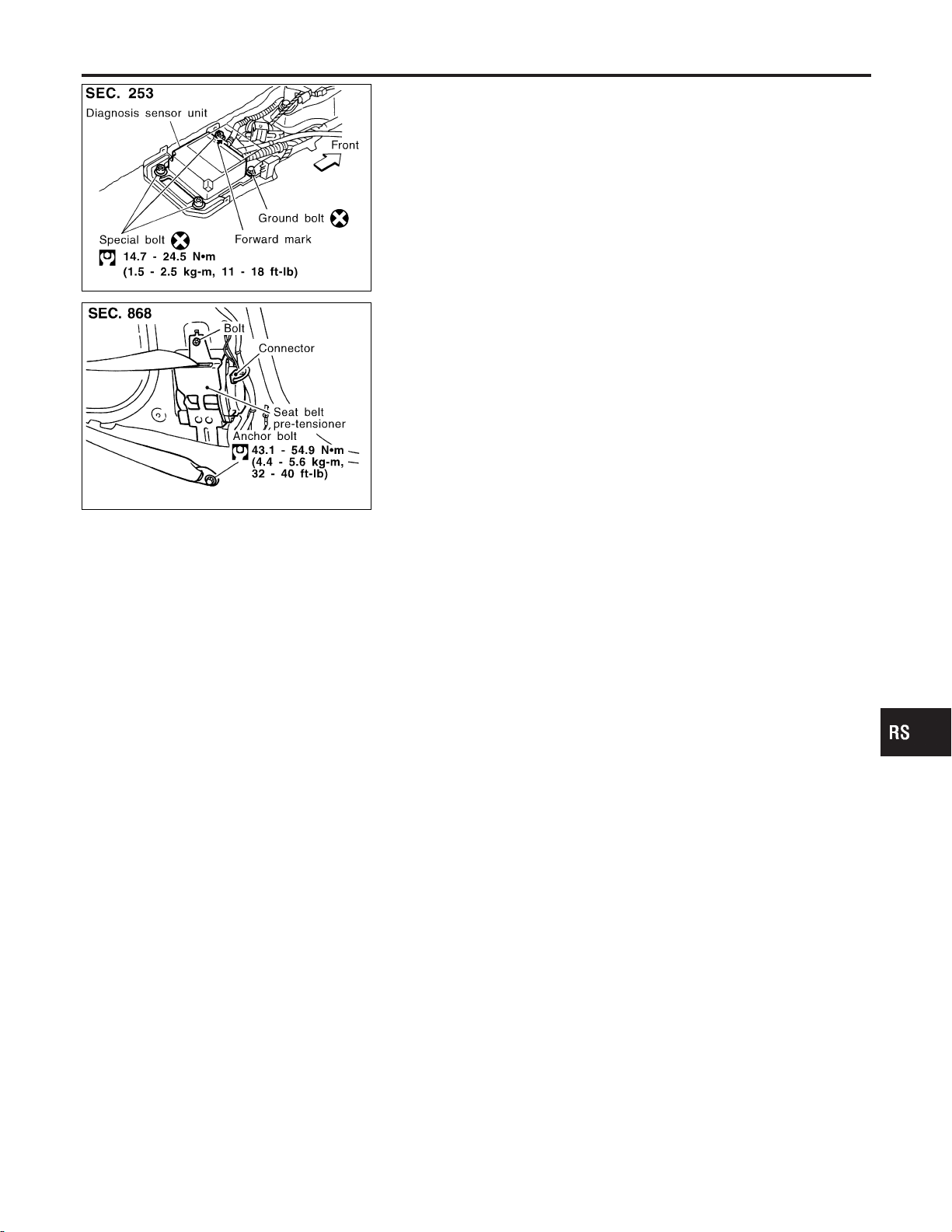
SUPPLEMENTAL RESTRAINT SYSTEM (SRS)
Diagnosis Sensor Unit (Cont’d)
1. Disconnect driver, passenger and side air bag module connectors. Also, disconnect seat belt pre-tensioner connector.
2. Remove console box. Refer to BT-28, “ INSTRUMENT PANEL
ASSEMBLY”.
3. Disconnect diagnosis sensor unit connector.
4. Remove ground bolt and also remove special bolts using the
TAMPER RESISTANT TORX (Size T50), from diagnosis sensor unit.
Then remove the diagnosis sensor unit.
NOTE:
SRS673-A
! To install, reverse the removal procedure sequence.
GI
MA
EM
SRS563-C
Seat Belt Pre-tensioner
REMOVAL AND INSTALLATION
CAUTION:
! Before servicing SRS, turn the ignition switch off, discon-
nect both battery cables and wait at least 3 minutes.
! Check seat belt pre-tensioner with load limiter for proper
installation.
! After replacement of seat belt pre-tensioner, check SRS
function and perform self-diagnosis for SRS.
Refer to “SRS Operation Check” for details. (RS-41)
! Do not attempt to disassemble seat belt pre-tensioner with
load limiter.
! Replace seat belt pre-tensioner if it has been dropped or
sustained an impact.
! Do not expose seat belt pre-tensioner to temperatures
exceeding 80°C (176°F).
For removal of seat belt pre-tensioner, refer to “Front Seat Belt” for
details. (RS-5)
NOTE:
! To install, reverse the removal procedure sequence.
NHRS0036
Satellite Sensor
REMOVAL AND INSTALLATION
CAUTION:
! Before servicing SRS, turn the ignition switch off, discon-
nect both battery cables and wait at least 3 minutes.
! Do not use old bolts coated with bonding agent after
removal; replace with new ones.
! Check satellite sensor for proper installation.
! Check satellite sensor to ensure they are free of
deformities, dents, cracks or rust. If it shows any visible
signs of damage, replace it with new one.
! After replacement of satellite sensor, check SRS function
and perform self-diagnosis for SRS. Refer to “SRS Operation Check” for details. (RS-41)
! Do not attempt to disassemble satellite sensor.
! Replace satellite sensor if it has been dropped or sus-
tained an impact.
NHRS0014
LC
EC
FE
AT
AX
SU
BR
ST
BT
HA
SC
EL
IDX
RS-19
Page 99

SUPPLEMENTAL RESTRAINT SYSTEM (SRS)
Satellite Sensor (Cont’d)
SRS674-A
REMOVAL AND INSTALLATION
1. Remove seat belt pre-tensioner. Refer to “Front Seat Belt” for
details. (RS-5)
2. Disconnect satellite sensor connector.
3. Remove bolt and nuts from satellite sensor unit.
Then remove the satellite sensor.
NOTE:
! To install, reverse the removal procedure sequence.
Driver Air Bag Module and Spiral Cable
NHRS0015
SRS566
SRS798-A
REMOVAL
NHRS0016
CAUTION:
! Before servicing SRS, turn the ignition switch off, discon-
nect both battery cables and wait at least 3 minutes.
! Always work from the side of air bag module.
1. Remove lower lid from steering wheel, and disconnect air bag
module connector.
2. Remove side lids, ASCD steering switch and TEL switch.
Using the TAMPER RESISTANT TORX (Size T30), remove left
and right special bolts. Air bag module can then be removed.
SBF812E
RS-20
Page 100

SUPPLEMENTAL RESTRAINT SYSTEM (SRS)
Driver Air Bag Module and Spiral Cable (Cont’d)
CAUTION:
! Always place air bag module with pad side facing upward.
! Do not attempt to disassemble air bag module.
! The special bolts are coated with bonding agent. Do not
use old bolts after removal; replace with new ones.
! Do not insert any foreign objects (screwdriver, etc.) into
air bag module connector.
SRS443
! Replace air bag module if it has been dropped or sus-
tained an impact.
! Do not expose the air bag module to temperatures exceed-
ing 90°C (194°F).
! Do not allow oil, grease or water to come in contact with
the air bag module.
GI
MA
EM
LC
EC
FE
AT
SBF814E
SRS676
SRS384
3. Set steering wheel in the neutral position.
4. Disconnect horn connector and remove nuts.
5. Remove dynamic damper. Then using steering wheel puller,
remove steering wheel. Be careful not to over-tighten puller
bolt on steering wheel.
CAUTION:
! Do not tap or bump the steering wheel.
6. Remove steering column cover.
7. Remove four spiral cable securing screws, and extract spiral
cable forward. Unlock spiral cable connector, then remove spiral cable.
CAUTION:
! Do not attempt to disassemble spiral cable.
! Do not apply lubricant to the spiral cable.
AX
SU
BR
ST
BT
HA
SC
EL
RS-21
IDX
 Loading...