


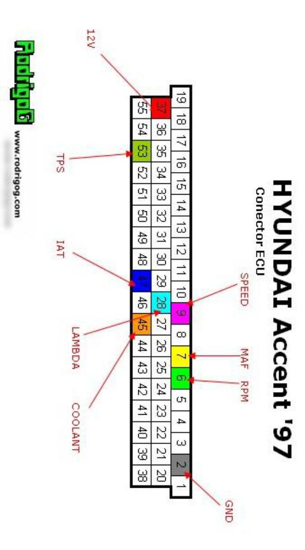
Descripción de pines: |
|
||
N° |
I/O |
Cable |
Descripción |
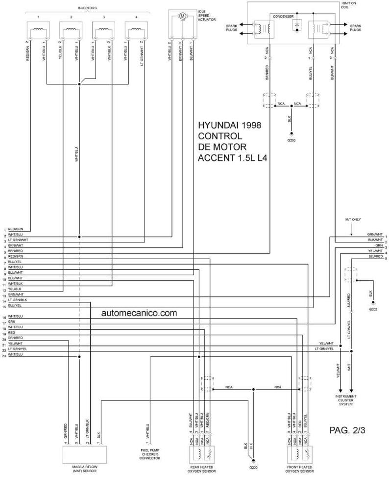
01 |
O |
café/rojo |
Control bobina alta tensión (Bujía 2 y 3) |
02 |
- |
negro |
Tierra |
03 |
O |
blanco/amarillo |
Relé control bomba de combustible |
04 |
O |
azul/blanco |
Control Abriendo válvula de relantí |
05 |
O |
rojo/negro |
Control de valvula solenoide de purga |
06 |
O |
verde claro/rojo |
Señal de revoluciones RPM a TCM |
07 |
I |
verde/rojo |
Flujómetro de aire (MAF) |
08 |
I |
verde |
Sensor de posición del árbol de levas |
09 |
I |
verde/blanco |
Entrada de velocidad del vehículo |
10 |
- |
negro |
Tierra |
11 |
I |
celeste |
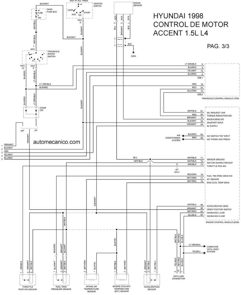
Sensor de cascabeleo (KNOCK) |
12 |
O |
verde/blanco |
Alimentación +5V para sensor de posición del acelerador (TPS) |
13 |
- |
blanco/rojo |
Comunicación OBDII |
14 |
- |
negro |
Tierra |
15 |
- |
- |
- |
16 |
O |
blanco/negro |
Control inyector 3 |
17 |
O |
rojo/verde |
Control inyector 1 |
18 |
I |
verde/blanco |
alimentación +12V para memoria |
19 |
- |
negro |
Tierra |
20 |
O |
azul/amarillo |
Control bobina de alta tensión (Bujía 1 y 4) |
21 |
O |
amarillo/azul |
Control indicador de falla |
22 |
O |
café/blanco |
Control Cerrando válvula de relantí |
23 |
- |
- |
- |
24 |
- |
negro |
Tierra |
25 |
- |
- |
- |
26 |
- |
azul/negro |
Tierra de flujómetro de aire |
27 |
I |
negro/blanco |
Partida ON |
28 |
I |
naranja |
Sensor de oxigeno (Lambda) |
29 |
- |
- |
- |
30 |
- |
negro |
Tierra de sensores |
31 |
- |
- |
- |
32 |
O |
rojo/amarillo |
Control relé aire acondicionado |
33 |
O |
amarillo/negro |
Control relé de ventilador del radiador |
34 |
O |
amarillo/negro |
Control inyector 2 |
35 |
O |
verde claro/blanco |
Control inyector 4 |
36 |
O |
negro/amarillo |
Control relé control ECM |
37 |
I |
blanco/azul |
Alimentación desde relé control ECM |
38 |
- |
- |
- |
39 |
- |
- |
- |
40 |
I |
café |
Sw presión de A/C |
41 |
I |
negro/rojo |
Respuesta A/C |
42 |
I |
verde/blanco |
Caja de cambios en neutro |
43 |
- |
- |
- |
44 |
- |
- |
- |
45 |
I |
blanco/rojo |
Sensor de temperatura del motor (COOLANT) |
46 |
- |
- |
- |
47 |
I |
blanco/verde |
Sensor de temperatura de aire (IAT) |
48 |
- |
café |
Tierra sensor de posición árbol de levas |
49 |
I |
negro/naranja |
Sensor de posición árbol de levas |
50 |
- |
- |
- |
51 |
- |
- |
- |
52 |
O |
verde |
Salida sensor de posición de acelerador (TPS) a TCM |
53 |
I |
verde/negro |
Sensor de posición de acelerador (TPS) |
54 |
- |
negro |
Tierra |
55 |
- |
Azul/negro |
Comunicación OBDII |

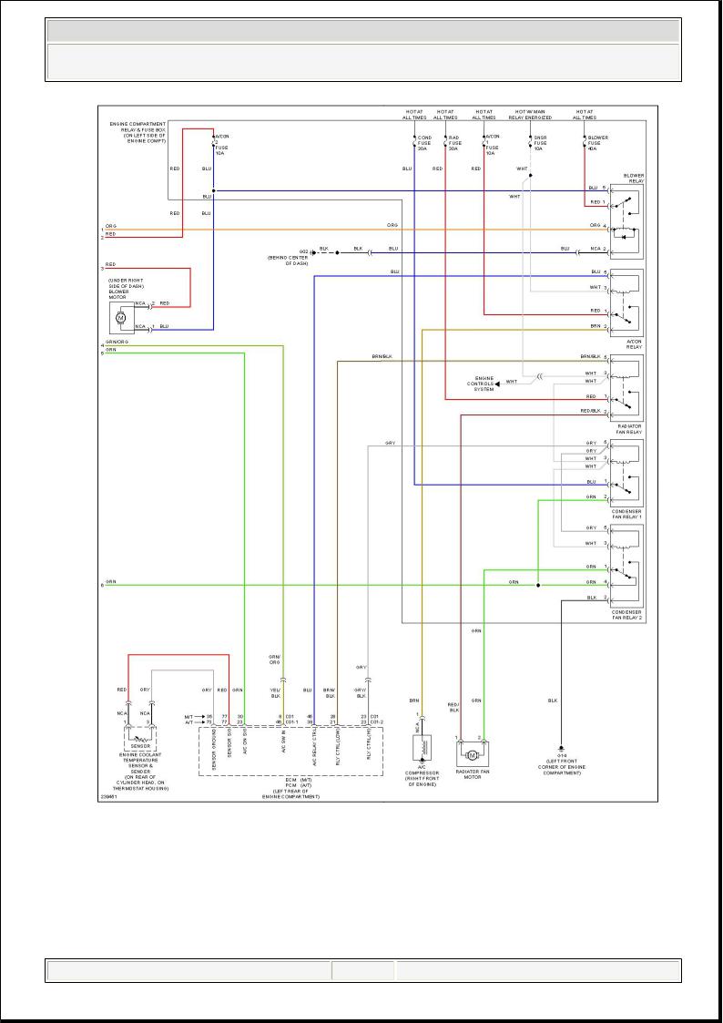
2006 Hyundai Accent GLS
SYSTEM WIRING DIAGRAMS
Fig. 1: Automatic A/C Circuit (1 of 2)
martes, 17 de marzo de 2015 19:00:02 |
Page 1 © 2005 Mitchell Repair Information Company, LLC. |
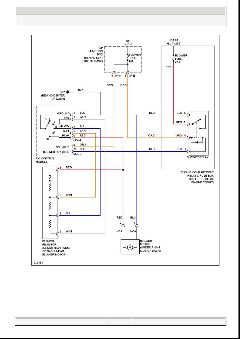
2006 Hyundai Accent GLS
SYSTEM WIRING DIAGRAMS
Fig. 2: Automatic A/C Circuit (2 of 2)
martes, 17 de marzo de 2015 19:00:29 |
Page 1 © 2005 Mitchell Repair Information Company, LLC. |
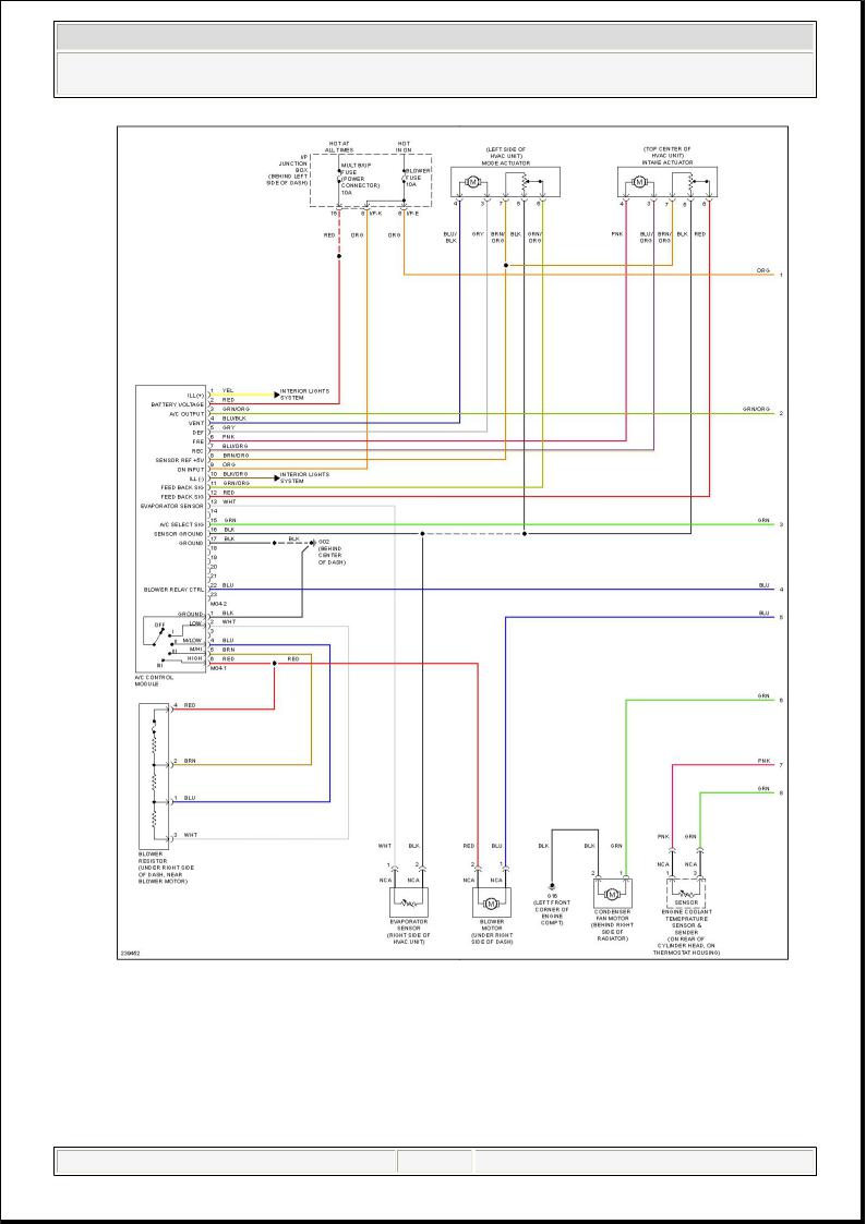
2006 Hyundai Accent GLS
SYSTEM WIRING DIAGRAMS
Fig. 3: Heater Circuit
martes, 17 de marzo de 2015 19:00:52 |
Page 1 © 2005 Mitchell Repair Information Company, LLC. |
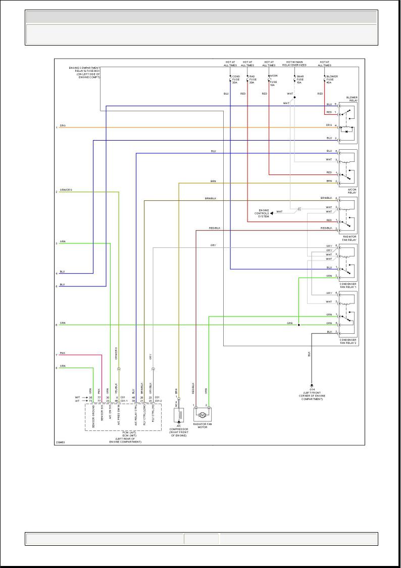
2006 Hyundai Accent GLS
SYSTEM WIRING DIAGRAMS
Fig. 4: Manual A/C Circuit (1 of 2)
martes, 17 de marzo de 2015 19:01:12 |
Page 1 © 2005 Mitchell Repair Information Company, LLC. |
2006 Hyundai Accent GLS
SYSTEM WIRING DIAGRAMS
Fig. 5: Manual A/C Circuit (2 of 2)
martes, 17 de marzo de 2015 19:01:29 |
Page 1 © 2005 Mitchell Repair Information Company, LLC. |
2006 Hyundai Accent GLS
SYSTEM WIRING DIAGRAMS
Fig. 6: Anti-lock Brakes Circuit
martes, 17 de marzo de 2015 19:01:49 |
Page 1 © 2005 Mitchell Repair Information Company, LLC. |
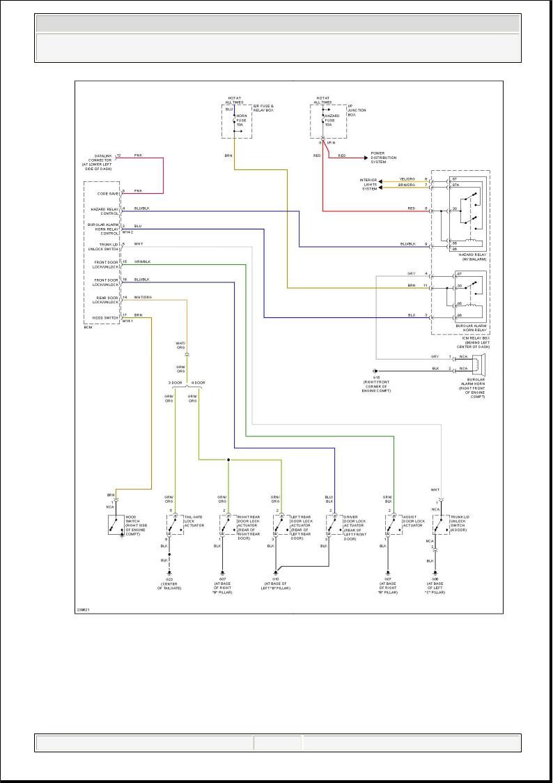
2006 Hyundai Accent GLS
SYSTEM WIRING DIAGRAMS
Fig. 7: Anti-theft Circuit
martes, 17 de marzo de 2015 19:02:08 |
Page 1 © 2005 Mitchell Repair Information Company, LLC. |
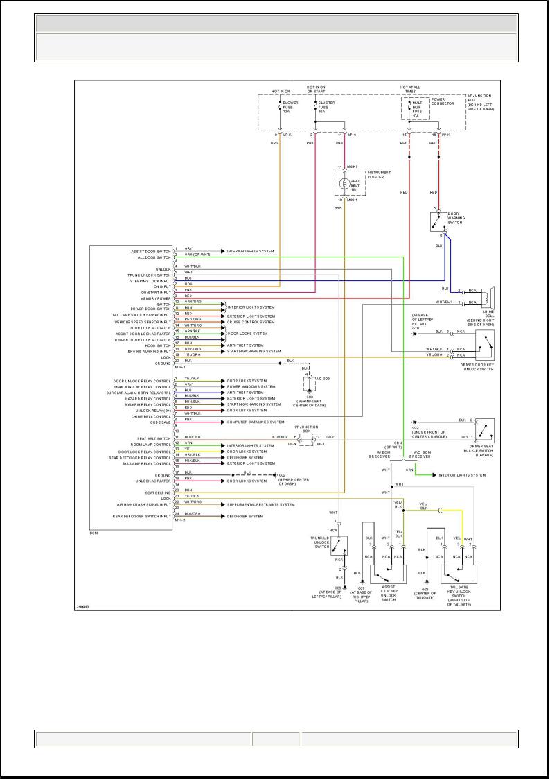
2006 Hyundai Accent GLS
SYSTEM WIRING DIAGRAMS
Fig. 8: Body Control Modules Circuit
martes, 17 de marzo de 2015 19:02:26 |
Page 1 © 2005 Mitchell Repair Information Company, LLC. |

2006 Hyundai Accent GLS
SYSTEM WIRING DIAGRAMS
Fig. 9: Computer Data Lines Circuit
martes, 17 de marzo de 2015 19:02:44 |
Page 1 © 2005 Mitchell Repair Information Company, LLC. |
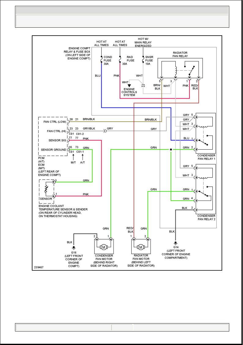
2006 Hyundai Accent GLS
SYSTEM WIRING DIAGRAMS
Fig. 10: Cooling Fan Circuit
martes, 17 de marzo de 2015 19:03:22 |
Page 1 © 2005 Mitchell Repair Information Company, LLC. |
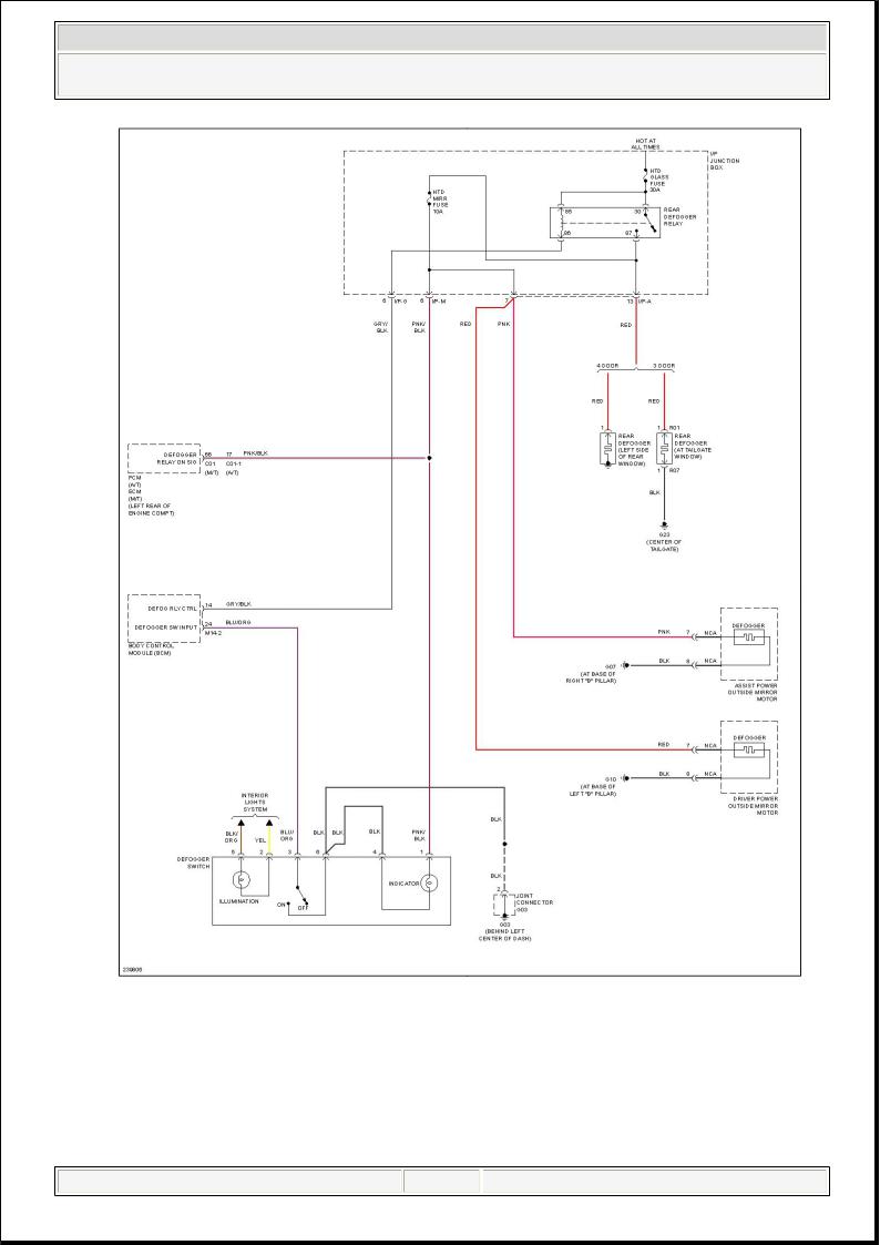
2006 Hyundai Accent GLS
SYSTEM WIRING DIAGRAMS
Fig. 11: Defoggers Circuit
martes, 17 de marzo de 2015 19:03:40 |
Page 1 © 2005 Mitchell Repair Information Company, LLC. |

2006 Hyundai Accent GLS
SYSTEM WIRING DIAGRAMS
Fig. 12: 1.6L, Engine Performance Circuit, A/T (1 of 4)
martes, 17 de marzo de 2015 19:04:08 |
Page 1 © 2005 Mitchell Repair Information Company, LLC. |
 Loading...