

Page 1

https://truckmanualshub.com/
EC Declaration of conformity - update 05/01/’10
1. We hereby declare that the following machine comply with the machine directive 2006/42/EC,
EMC-directive 2004/108/EC, Non-road mobile machinery emission directive 97/68/EC (amended by
2002/88/EC, 2004/26/EC, 2006/105/EC) and noise emission 2000/14/EC (amended by 2005/88/EC).
Forklifts Model :
Serial Nr. :
2. Manufacturer Hyundai Heavy Industries Co. Ltd.
1 Chonha-Dong, Dong-Ku
Ulsan
The republic of Korea
Authorized representative :
Owner of the technical fi le for
machine production.
(TCF : Technical Construction File)
3. Harmonized European directives : ISO3691-1.3, ISO 20898:2008, EN ISO 2867:2008
4. Noise level :
Certain n˚ :
Date :
Conformity assessment procedure :
Authorized entity :
Engine power :
Guaranteed sound power level :
Hyundai Heavy Industries Europe N.V.
Vossendal 11
2440 Geel
Belgium
e13*2000/14*2005/88*0059*08
2009-06-17
Attachment VIII following the periodical inspection on technical
extended with “Information on the scope of delivery” by TÜV
Rheinland.
Société Nationale de Certification et d’Homologation s.à r.l
CE0499 11, route de Luxembourg
5230 Sandweiler
Luxemburg
*** kW
*** dB (A)
*******
***
5. Remarks
*****
Managing Director
Geel, Belgium
**/**/****
Page 2

Lift trucks are specialized machines with unique operating characteristics, designed to perform a specific
job. Their function and operation is not like a car or ordinary truck. They require specific instructions
and rules for safe operation and maintenance.
Safe operation of lift trucks is of primary importance to HYUNDAI.
Our experience with lift truck accidents has shown that when accidents happen and people are killed or
injured, the causes are:
ÂÂ
Operator not properly trained
Â
Operator not experienced with lift truck operation
ÂÂ
Basic safety rules not followed
Â
Lift truck not maintained in safe operating condition
For these reasons, HYUNDAI wants you to know about the safe operation and correct maintenance of
your lift truck.
This manual is designed to help you operate your lift truck safely.
This manual shows and tells you about safety inspections and the important general safety rules and
hazards of lift truck operation. It describes the special components and features of the truck and
explains their function. The correct operating procedures are shown and explained. Illustrations and
important safety messages are included for clear understanding. A section on maintenance and
lubrication is included for the lift truck mechanic.
The operator's manual is not a training manual. It is a guide to help trained and authorized operators
safety operate their lift truck by emphasizing and illustrating the correct procedures. However, it cannot
cover every possible situation that may result in an accident. You must watch for hazards in your work
areas and avoid or correct them. It is important that you know and understand the information in this
manual and that you know and follow your company safety rules!
Be sure that your equipment is maintained in a safe condition. Do not operate a damaged or
malfunctioning truck. Practice safe operation every time you use your lift truck. Let's join together to set
high standards in safety.
Remember, before you start operating this lift truck, be sure you understand all driving procedures. It is
your responsibility, and it is important to you and your family, to operate your lift truck safely and
efficiently.
Be aware that the Federal Occupational S
afety and Health Act(OSHA) and state laws require
that operators be completely trained in the safe operation of lift trucks; It is also an (OSHA)
requirement that a machine inspection be performed before every shift. If you need training in
operating or inspecting your lift truck, ask your supervisor.
HYUNDAI lift trucks are built to take hard work, but not abuse. They are built to be dependable, but they
are only as safe and efficient as the operator and the persons responsible for maintaining them. Do not
make any repairs to this truck unless you have been trained in safe lift truck repair procedures and are
authorized by your employer.
This manual describes procedures for operation, handling, lubrication, maintenance, checking and
adjustment. It will help the operator realize peak performance through effective, economical and safe
machine operation.
A MESSAGE TO HYUNDAI LIFT TRUCK OPERATORS
0-1
https://truckmanualshub.com/
Page 3

HYUNDAI welcomes you to the growing group of professionals who own, operate and maintain
HYUNDAI lift trucks. We take pride in the long tradition of quality products and superior value the
HYUNDAI name represents. This manual familiarizes you with safety, operating, and maintenance
information about your new lift truck. It has been specially prepared to help you use and maintain your
HYUNDAI lift truck in a safe and correct manner.
Your HYUNDAI lift truck has been designed and built to be as safe and efficient as today's technology
can make it. As manufactured, for some models, it meets all the applicable mandatory requirements of
ANSI B56.1-1988 Safety Standard for Powered Industrial Trucks. Some trucks are also furnished with
equipment to help you operate safety; for example, load back rest, parking brake and horn are standard
equipment.
Safe, productive operation of a lift truck requires both skill and knowledge on the part of the operator.
The operator must know, understand, and practice the safety rules and safe driving and load handling
techniques described in this manual. To develop the skill required, the operator must become familiar
with the construction and features of the lift truck and how they function, the operator must understand
its capabilities and limitations, and see that it is kept in a safe condition.
Routine Servicing and Maintenance
Regular maintenance and care of your lift truck is not only important for economy and utilization
reasons; it is essential for your safety. A faulty lift truck is a potential source of danger to the operator,
and to other personnel working near it. As with all quality equipment, keep your lift truck in good
operating condition by following the recommended schedule of maintenance.
Operator Daily Inspection - Safety and Operating Checks
A lift truck should always be examined by the operator, before driving, to be sure it is safe to operate.
The importance of this procedure is emphasized in this manual with a brief illustrated review and later
with more detailed instructions. HYUNDAI dealers can supply copies of a helpful
Dri
vers Daily
Checklist.
It is an OSHA requirement.
Planned Maintenance
In addition to the daily operator inspection, HYUNDAI recommends that a planned maintenance and
safety inspection program(PM) be performed by a trained and authorized mechanic on a regular basis.
The PM will provide an opportunity to make a thorough inspection of the safety and operating condition
of your lift truck. Necessary adjustments and repairs can be done during the PM, which will increase the
life of components and reduce unscheduled downtime and increase safety. The PM can be scheduled
to meet your particular application and lift truck usage.
The procedures for a periodic planned maintenance program that covers inspections, operational
checks, cleaning, lubrication, and minor adjustments are outlined in this manual. Your HYUNDAI dealer
is prepared to help you with a Planned Maintenance Program by trained service personnel who know
your lift truck and can keep it operating safely and efficiently.
Service Manual
In-depth service information for trained service personnel is found in Service Manual.
INTRODUCTION
0-2
https://truckmanualshub.com/
Page 4

This manual is a digest of essential information about the safe operation, the features and functions and
explains how to maintain your lift truck. This manual is organized into nine major parts:
Section 1. Safety hints
, reviews and illustrates accepted practices for safe operation of a lift truck.
Section 2. Operating Hazards
, warns of conditions that could cause damage to the truck or injury to
the operator or other personnel.
Section 3. Know Your Truck
, describes the major operating components, systems, controls, and other
features of your truck and tells how they function.
Section 4. Operator Maintenance and Care
, presents details on how to perform the operator's daily
safety inspection and refuel the lift truck.
Section 5. Starting and Operating Procedures
, discusses specific instructions on the safe, efficient
operation of your lift truck.
Section 6. Emergency Starting and Towing
, gives instructions for towing your truck in an emergency
and for using battery jumper cables to start your truck in an emergency.
Section 7. Planned Maintenance and Lubrication
, describes the PM (Planed Maintenance) program.
Section 8. Specifications
, provides reference information and data on features, components, and
maintenance items.
Section 9. Troubleshooting
, provides trouble symptoms, causes and methods of remedy.
Section10. Testing and Adjusting
, gives instructions for testing and adjusting.
ö
TThe descriptions and specifications included in this manual were in effect at the time of printing.
HYUNDAI reserves the right to make improvements and changes in specifications or design, without
notice and without incurring obligation. Please check with your authorized HYUNDAI dealer for
information on possible updates or revisions.
The examples, illustrations, and explanations in this manual should help you improve your skill and
knowledge as a professional lift truck operator and take full advantage of the capabilities and safety
features of your new lift truck.
The first section of the manual is devoted to a review, with illustrations and brief messages, of general
safety rules and the major operating hazards you can encounter while operating a lift truck. Next, you
will find description's of the components of your specific lift truck model and how the instruments,
gauges, and controls operate. Then, you will find a discussion of safe and efficient operating
procedures, followed by instruction's on how to tow a disabled lift truck. The later sections of the manual
are devoted to maintenance and truck specifications.
Take time to carefully read the
Know Your Truck
section. By acquiring a good basic understanding of
your truck's features, and how they function, you are better prepared to operate it both efficiently and
safely.
In
Planned Maintenance
, you will find essential information for correct servicing and periodic
maintenance of your truck, including charts with recommended maintenance intervals and component
capacities. Carefully follow these instructions and procedures.
Each major section has its own table of contents, so that you can find the various topics more easily.
HOW TO USE THIS MANUAL
0-3
https://truckmanualshub.com/
Page 5

We urge you to first carefully read the manual from cover to cover. Take time to read and understand
the information on general safety rules and operating hazards. Acquaint yourself with the various
procedures in this manual. Understand how all gauges, indicator lights, and controls function. Please
contact your authorized HYUNDAI dealer for the answers to any questions you may have about your lift
truck's features, operation, or manuals.
Operate your lift truck safely; careful driving is your responsibility.
Drive defensively and think about the safety of people who are working nearby. Know your truck's
capabilities and limitations. Follow all instructions in this manual, including all symbols( ) and
messages to avoid damage to your lift truck or the possibility of any harm to yourself or others.
This manual is intended to be a permanently attached part of your lift truck. Keep it on the truck as a
ready reference for anyone who may drive or service it. If the truck you operate is not equipped with a
manual, ask your supervisor to obtain one and have it attached to the truck. And, remember, your
HYUNDAI dealer is pleased to answer any questions about the operation and maintenance of your lift
truck and will provide you with additional information should you require it.
ö
I
Illustrations may differ from your machine, but they are applicable to your machine.
ö
0-4
https://truckmanualshub.com/
Page 6

Â
Noise level (2000/14/EC and EN 12053) are as followings.
EC REGULATION APPROVED
Model
15D/18D/20DA-7E
20D/25D/30D/33D-7E
20DF/25DF/30DF/33DF-7, 35DF-7
35D/40D/45D-7E, 50D-7AE
35DS/40DS/45DS/50DA-7E
50D/60D/70D-7E, 80D-7E
50DF/60DF/70DF-7
50DS/60DS/70DS-7E
LPA
81
dB
80
dB
80
dB
82
dB
82
dB
82
dB
82
dB
82
dB
LWA(EU only)
101
dB
103
dB
103
dB
106
dB
106
dB
107
dB
107
dB
107
dB
Â
The value of vibrations transmitted by the operator's seat are lower than standard value of
(2002/44/EC)
0-5
https://truckmanualshub.com/
Page 7
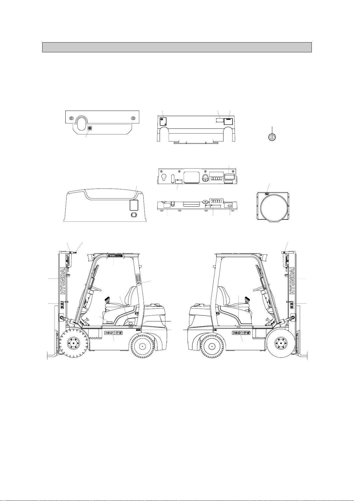
1. LOCATION
Always keep these labels clean. If they are lost or damaged, attach them again or replace them with
new labels.
15D/18D/20DA-7E
SAFETY LABELS
0-6
1 Logo
2 Warning plate
3 Tire caution
4 Air intake
5 Start key
6 Radiator & fan
8 Hydraulic oil
10 Start warning
11 Hand caution
12 Diesel fuel
13 Temperature
14 Parking brake
15 Warning safety
16 Hook
17 Safety instruction
18 Brake fluid
20 Model name
21 Noise
22 Load chart
23 Label(UL)
24 Name plate(CE)
25 Name plate(UL)
26 Fuse
27 Bonnet cover
START SWITCH
5
12
15
11
16
1
2
20
8
20
1
2
16
27
3
10
18
14
DASHBOARD COVER
DASHBOARD
SUB BONNET
BONNET
FAN SHROUD
17
6
24
,
25
13
22
21
16
4
23
26
15D7EOM101
1)
https://truckmanualshub.com/
Page 8
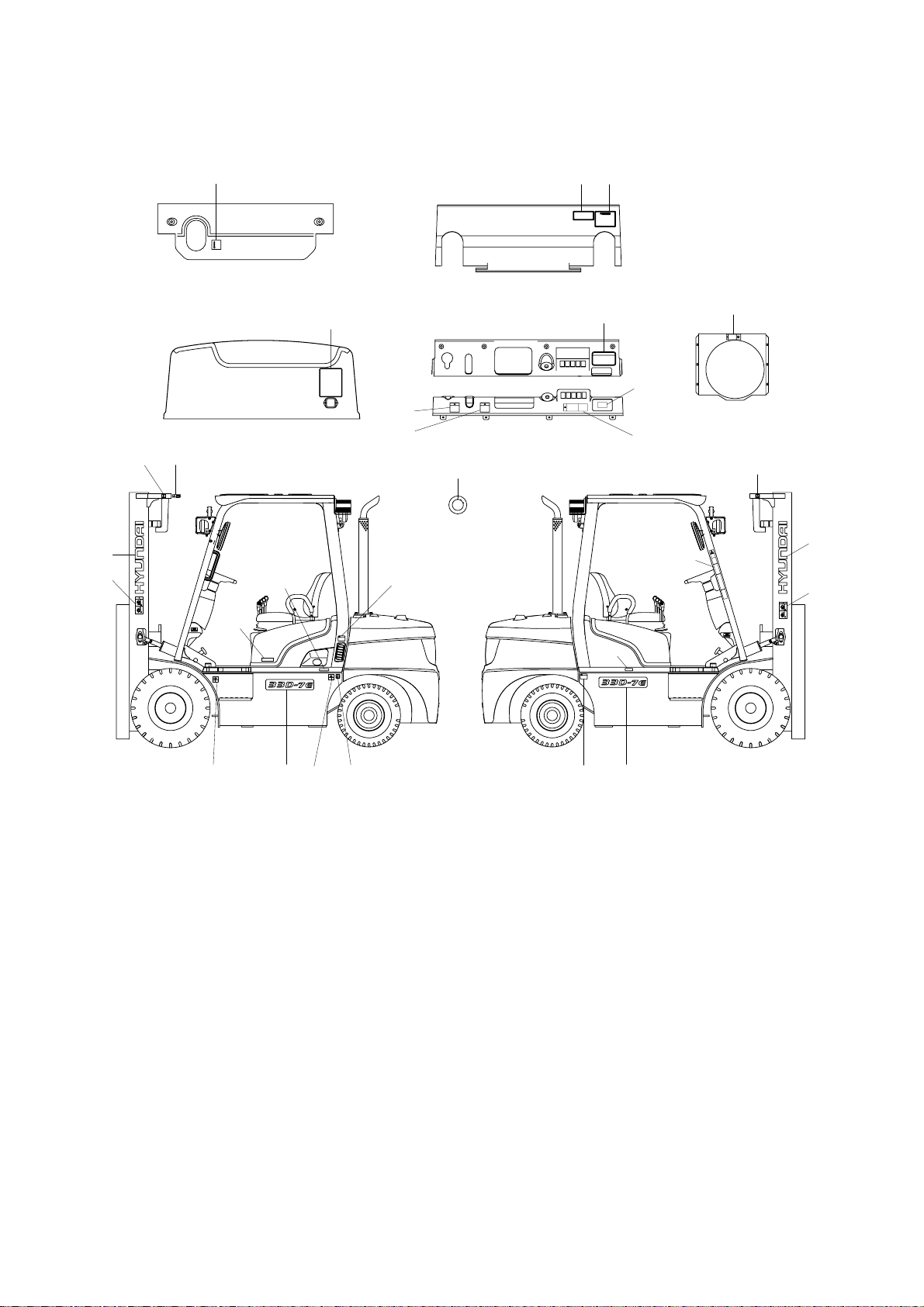
20D/25D/30D/33D-7E
TRAVEL power can be shutdown
When an operator leaves more than 3seconds
without parking and neutral position.
SAFETY INSTRUCTION
ENGINE AIR INTAKE
KEEP WATER AND OTHER
FOREIGN MATERIALS OUT.
A
B
C
D
91FJ-00180
91FP-00340
A
B
C
D
91FP-00340
SUB BONNET
13
BONNET
22
DASHBOARD
DASHBOARD COVER
FAN SHROUD
17
14
18
10
6
START SWITCH
5
16
11
1
2
15
12
20
24, 25
8
LOAD CAPACITY CHART
16
2
1
16
3
3
26
27
20
4
3
23
20D7EOM101
2)
0-7
1 Logo
2 Warning plate
3 Tire caution
4 Air intake
5 Start key
6 Radiator & fan
8 Hydraulic oil
10 Start warning
11 Hand caution
12 Diesel fuel
13 Temperature
14 Parking brake
15 Warning safety
16 Hook
17 Safety instruction
18 Brake fluid
20 Model name
21 Noise
22 Load chart
23 Label(UL)
24 Name plate(CE)
25 Name plate(UL)
26 Fuse
27 Bonnet cover
https://truckmanualshub.com/
Page 9

20DF/25DF/30DF/33DF-7, 35DF-7
91FP-00340
A
B
C
D
13
22
5
16
11
1
2
14
18
9
26
17
24, 25
6
FAN SHROUD
27
3 20 12 3 16
8
BONNET
DASH BOARDSUB BONNET
DASH BOARD COVER
START SWITCH
15
21
4
23
35DFOM101
3)
1 Logo
2 Warning plate
3 Tire caution
4 Air intake
5 Start key
6 Radiator & fan
8 Hydraulic oil
10 Start warning
11 Hand caution
12 Diesel fuel
13 Temperature
14 Parking brake
15 Warning safety
16 Hook
17 Safety instruction
18 Brake fluid
20 Model name
21 Noise
22 Load chart
23 Label(UL)
24 Name plate(CE)
25 Name plate(UL)
26 Fuse box
27 Bonnet cover
0-8
https://truckmanualshub.com/
Page 10
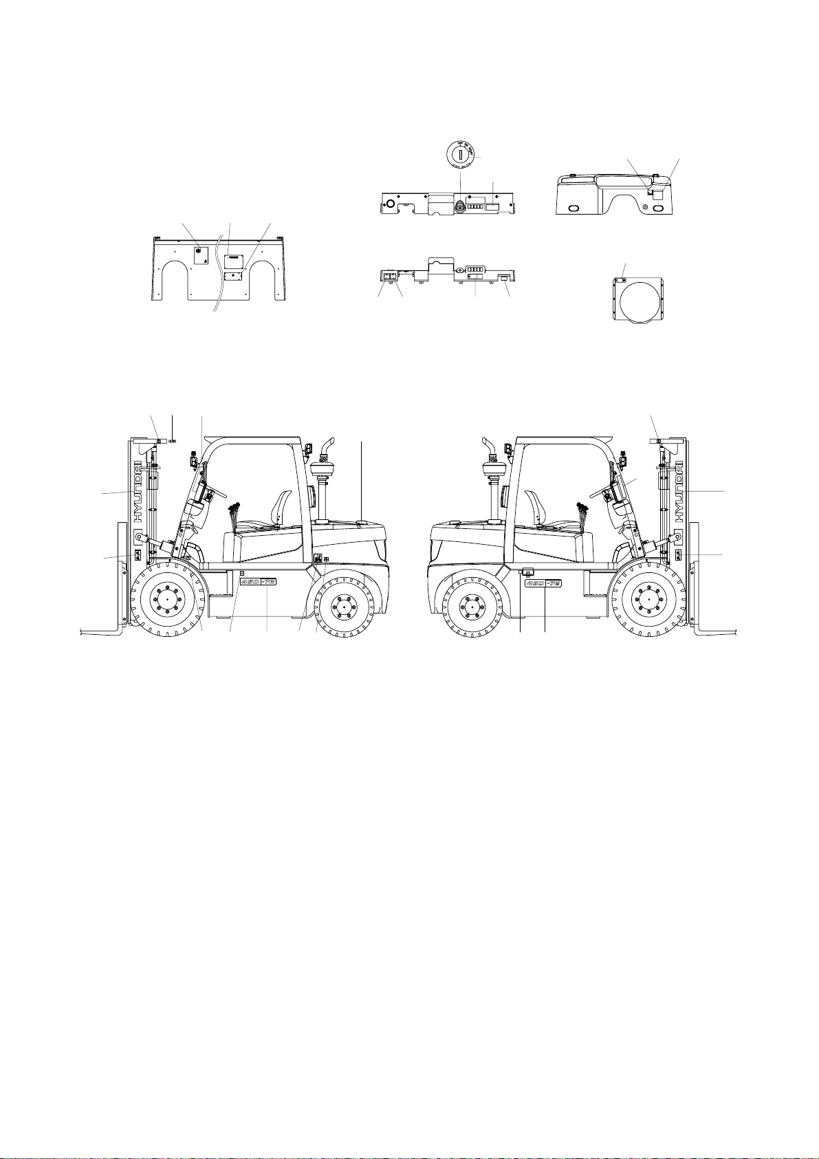
35D/40D/45D-7E, 50D-7AE, 35DS/40DS/45DS/50DA-7E
5
16
11
1
2
15
29
8
25
18
28
6
22
10
14
12
20
20
1
2
16
13
91FP-00340
91FP-00340
15
BONNET
FAN SHROUD
DASH BOARD
DASH BOARD COVER
26
21
24
23,
17
3
3
35D7EOM101
4)
0-9
1 Logo
2 Warning plate
3 Tire caution
5 Start key
6 Radiator & fan
8 Hydraulic oil
10 Start warning
11 Hand caution
12 Diesel fuel
13 Temperature
14 Parking brake
15 Warning safety
16 Hook
17 Safety instruction
18 Brake fluid
20 Model name
21 Noise
22 Load chart
23 Label(UL)
24 Name plate(CE)
25 Name plate(UL)
26 Fuse
28 Engine room
29 Hanger
https://truckmanualshub.com/
Page 11

50D/60D/70D-7E, 80D-7E
5
10
6
14
FAN SHROUD
PARKING BRAKE
DASH BOARD COVER
32 12 19
13
32 1931
HEAD GUARD
22
21
23
25
15 16
1
2
26
28
16
20
28
17
2083
16
3
1
2
16 11
30
28
24
80D7EOM101
5)
0-10
1 Logo
2 Warning plate
3 Tire caution
5 Start key
6 Radiator cap & fan
8 Hydraulic oil
10 Start warning
11 Hand caution
12 Fuel
13 Temperature
14 Parking brake
15 Warning safety
16 Hook
17 Safety instruction
19 No step
20 Model name
21 Noise
22 Load chart
23 Label-UL
24 Name plate (CE)
25 Name plate (UL)
26 Fuse
28 Engine room
30 Cab tilting warning
31 Accumulator
32 Safety work
https://truckmanualshub.com/
Page 12

50DS/60DS/70DS-7E
25
10
14
24
,
26
23
21
17
18
START SWITCH
5
DASHBOARD COVER
DASHBOARD
FAN SHROUD
6
13
3
22
8
11
20
1
2
29
16
15
2
11
16
1
20
3
12
31
50DS7EOM101
6)
1 Logo
2 Warning plate
3 Tire caution
5 Start key
6 Radiator & fan
8 Hydraulic oil
10 Start warning
11 Hand caution
12 Diesel
13 Temperature
14 Parking brake
15 Warning safety
16 Hook
17 Safety instruction
18 Brake fluid
20 Model name
21 Noise
22 Load chart
23 Label(UL)
24 Name plate(CE)
25 Name plate(UL)
26 Fuse
29 Hanger
31 Accumulator
0-11
https://truckmanualshub.com/
Page 13
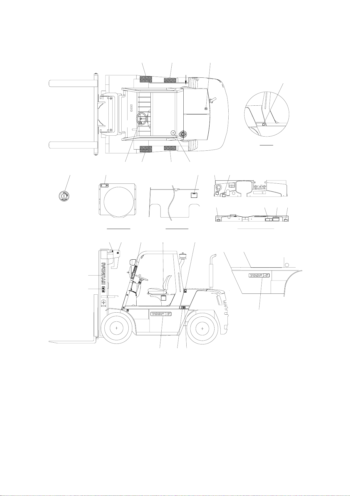
50DF/60DF/70DF-7
DASH BOARDFAN SHROUD DASH BOARD COVER
VIEW A
32 32 13
12
A
26 32 32 31
5 6 24 18 14
10 17 2121
16 11
1
2
15 22
20
20
19
83
50DF7OM101
7)
1 Logo
2 Warning plate
3 Tire caution
5 Start key
6 Radiator cap & fan
8 Hydraulic oil
10 Start warning
11 Hand caution
12 Fuel
13 Temperature
14 Parking brake
15 Warning safety
16 Hook
17 Safety instruction
18 Brake fluid wet
19 Hanger
20 Model name
21 Grease
22 Load capacity
24 Name plate (CE)
26 Sound
31 Accumulator
32 Safety work
0-12
https://truckmanualshub.com/
Page 14

2. DESCRIPTION
There are several specific warning labels on this machine please become familiarized with all warning
labels. Item numbers are based on the 15D/18D/20DA-7E
Replace any safety label that is damaged, or missing.
WARNING PLATE
(item 2)
This warning label is positioned on the both
side of the mast.
Never stand or work under the raised
forks even if the hydraulic safety lock
lever is
applied.
In case of working under the forks, it is
essential to support the carriage with
blocks.
1)
TEMPERATURE
(item 13)
This warning label is positioned on the left
of top side of sub bonnet.
Coolant must be checked as specified in
the maintenance chart.
2)
0-13
053
+07
20DE0FW06
25L7A0OM06
https://truckmanualshub.com/
053
+07
㷔,
92SB-00250
㶊
Page 15
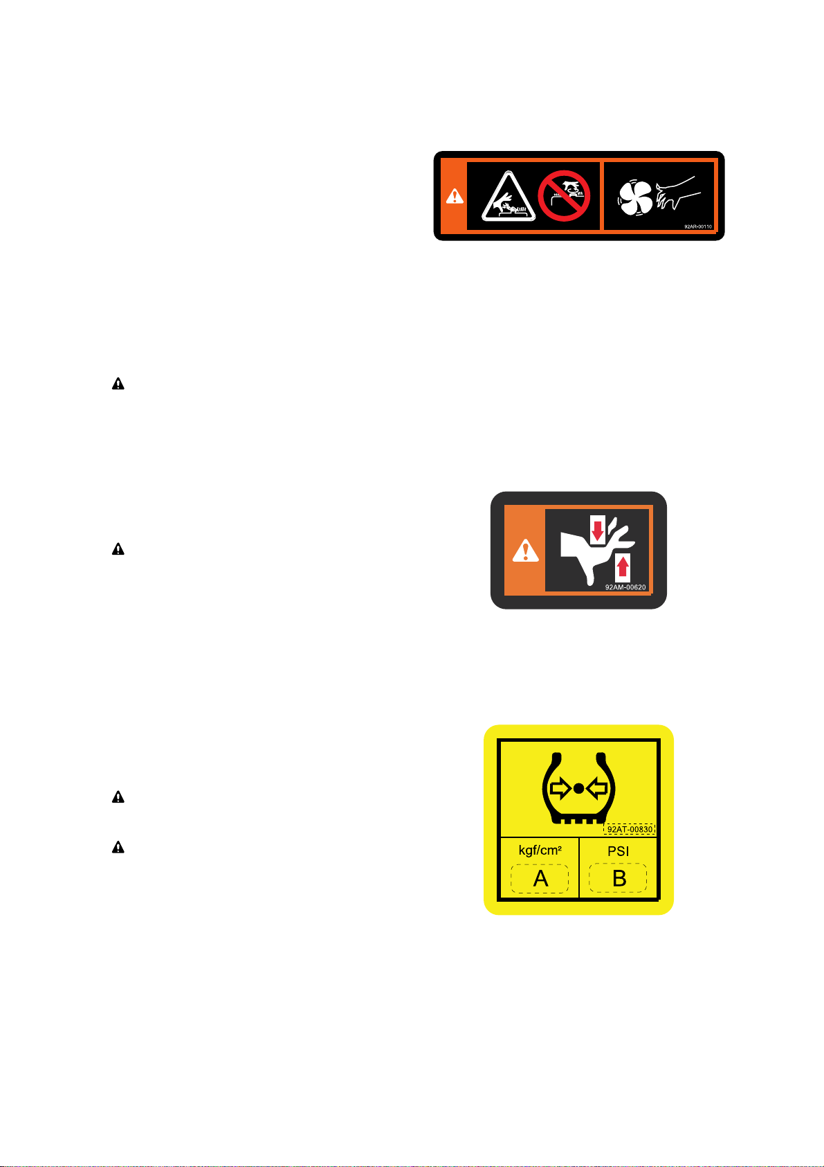
RADIATOR CAP & FAN
(item 6)
This warning label is positioned on the
cooling fan shroud of the radiator to warn of
the danger or injury from spinning fan
blades and forbid to open the filler cap of
the radiator because operator might get
scalded due to spouting of hot water. When
the engine is running. Be sure that you keep
your hands, fingers, arms, and clothing
away from a spinning fan. Don't stand in line
with a spinning fan. Fan blades can break at
excessively high RPM and be thrown out of
the engine compartment.
Never open the filler cap while engine
running or at high coolant temperature.
3)
25L7A0OM07
HAND CAUTION
(item 11)
This label is positioned on respectively near
the front fender and the rear fender of the
left side of the main frame.
It warns of the danger of injury from
move m ent betw e en rails , c hains,
sheaves, fork carr
iage, and other parts of
the mast assembly. Do not climb on or
reach into the mast. Personal injury wil
l
result if any part of your body is put
between moving parts of the mast.
4)
TIRE CAUTION
(item 3)
This label is positioned on both side of main
frame.
Tire p ressure m ust be chec k ed in
accordance with the maintenance chart.
Refer to page 5-3
for the regulated tire
air pressure(A and B).
5)
35DEOM103
20DEOM104
0-14
https://truckmanualshub.com/
Page 16

0-15
50D7EFW04
CABIN TILTING WARNING
(item 30)
This warning label is positioned on the left
top side of the frame.
Refe r to p age 7- 28 fo r safe tilt i ng
procedures.
7)
HOOK (
item 16)
This warning label is positioned respectively
on the both top side of mast and near rear
tire of the both side of the main frame.
Ref er to page 7-5 9 f or safe loading
procedures.
6)
92FT-40640
50DEOM35
SAFETY INSTRUCTION
(item 17)
This warning label is positioned on the
dashboard cover if the truck is for USA or
equipped with *
OPSS
.
This forklift is equipped with an operator
exis t ence sensing syst e m pe r
ANSI/
ASME B56.1-7.21.10 / 7.21.11 and
ASME ISO 3691.
Powered travel movement of the truck shall
be possible only if the operator is in the
normal operating position. Transmission will
automatically shift to neutral upon the exiting
of the operator.
The forward/reverse lever must be cycled
through neutral with the operator in the
normal operating position to regain powered
direction control.
8)
1.
2.
25L7A0OM02
OPSS : Operator Presence Sensing System
https://truckmanualshub.com/
Page 17

PARKING BRAKE
(item 14)
This warning plate is located on the right
side of the parking brake lever.
Pull by sufficient tension for constant
parking ability.
11)
ö
SSTART WARNING
(item 10)
This warning and caution plate are located
on the right side of the dashboard cover.
Start key switch after 5~6 seconds from
ON posi t ion. I t n eeds appr o x 5 ~6
seconds to se
t correct position of throttle.
Warnings before leaving the operator seat.
Be sure to lower the attachment to the
ground.
Apply the parking brake.
Cautions before starting or operating the
truck.
Put the gear shift lever in the neutral.
Apply the brake.
Read this operator's manual carefully.
10)
ö
1.
2.
0-16
92AD-00920
P
5 6'
~
I
50DEFW55
25L7A0OM04
-
-
-
-
-
BRAKE FLUID
(item 18)
This warning label is located on the left side
of dashboard cover.
9)
25L7A0OM03
https://truckmanualshub.com/
Page 18

0-17
25L7AOM09-1
WARNING SAFETY
(item 15)
This warning label is positioned on the front
outside of overhead guard stay-LH.
Refer to operator's manual in detail.
Always buckle up the seat belt for safety
operation.
When the operator get off the machine,
always pull the parking brake lever so that
the machine can keep with stopping
condition.
The people should not pass through
under forks and other attachments which
are lifted or being lifted.
Do not jump down from the machine. It
can be caused that the operator have
severe injury or death in the event of a tip
over.
Outstretch the legs as widely as possible
and grasp firmly the steering handle.
Learn the body to the opposite direction
in order to avoid severe injury or death
when the machine is tipped over.
Refer to page 3-8 for details.
12)
Η
Θ
Ι
Κ
Λ
Μ
Ν
ö
NNOISE
(item 21)
This warning plate is located on the front
side of dashboard.
13)
35L7FW09
BONNET COVER
(item 27)
This decal is located on the left bottom side
of the bonnet cover.
Before open the bonnet cover, be sure to
open the cain rear doors.
14)
https://truckmanualshub.com/
1
2
3
4
5
6
7
Page 19

1. DIRECTION
GUIDE
The directions of this machine indicate forward,
backward, right and left when machine is in the
travelling direction.
Left
Right
Front
Rear
D255SM01
2. SERIAL NUMBER
Inform following when you order parts or the machine is out of order.
MACHINE SERIAL NUMBER
It's shown on front of the right side frame.
1)
D255SM02
Important safety hint
It indicates matters which can cause the great loss on the machine or the surroundings.
It indicates the useful information for operator
3. SYMBOLS
ö
0-18
https://truckmanualshub.com/
Page 20

CONTENTS
FOREWORD
A message to hyundai lift truck operators
------------------------------------------------------------
0-1
Introduction
-----------------------------------------------------------------------------------------------------------------
0-2
How to use this manual
--------------------------------------------------------------------------------------------
0-3
EC regulation approved
-------------------------------------------------------------------------------------------
0-5
Safety labels
---------------------------------------------------------------------------------------------------------------
0-6
Guide(Direction, Serial number, Symbols)
-----------------------------------------------------------
0-18
1. SAFETY HINTS
1. Daily inspection
-----------------------------------------------------------------------------------------------------
1-1
2. Do's and don'ts
------------------------------------------------------------------------------------------------------
1-2
3. Seat belts
---------------------------------------------------------------------------------------------------------------
1-4
4. No riders
-----------------------------------------------------------------------------------------------------------------
1-5
5. Pedestrians
------------------------------------------------------------------------------------------------------------
1-6
6. Operator protection
----------------------------------------------------------------------------------------------
1-7
7. Fork safety
-------------------------------------------------------------------------------------------------------------
1-8
8. Pinch points
-----------------------------------------------------------------------------------------------------------
1-9
9. Travel
-----------------------------------------------------------------------------------------------------------------------
1-10
10. Grades, ramps, slopes and inclines
------------------------------------------------------------------
1-11
11. Tip over
-------------------------------------------------------------------------------------------------------------------
1-12
12. Surface and capacity
-------------------------------------------------------------------------------------------
1-14
13. Parking
--------------------------------------------------------------------------------------------------------------------
1-15
14. Refueling
----------------------------------------------------------------------------------------------------------------
1-16
15. Step
-------------------------------------------------------------------------------------------------------------------------
1-17
16. Operator's safety rules
----------------------------------------------------------------------------------------
1-18
2. OPERATING HAZARDS
1. Loose loads
-----------------------------------------------------------------------------------------------------------
2-1
2. Long and wide loads
--------------------------------------------------------------------------------------------
2-2
3. Rear swing
-------------------------------------------------------------------------------------------------------------
2-2
4. Low overhead clearance
-------------------------------------------------------------------------------------
2-3
5. Fast turns and high loads
-----------------------------------------------------------------------------------
2-3
6. Drop-offs
----------------------------------------------------------------------------------------------------------------
2-4
7. Right angle stacking
---------------------------------------------------------------------------------------------
2-4
8. Chain slack
------------------------------------------------------------------------------------------------------------
2-5
9. Pallets and skids
---------------------------------------------------------------------------------------------------
2-5
10. Caution for electrical lines
----------------------------------------------------------------------------------
2-6
11. Lifting loads
------------------------------------------------------------------------------------------------------------
2-7
https://truckmanualshub.com/
Page 21

3. KNOW YOUR TRUCK
1. General locations
--------------------------------------------------------------------------------------------------
3-1
2. Data/safety plates and decals
----------------------------------------------------------------------------
3-7
3. Instruments and controls
------------------------------------------------------------------------------------
3-9
4. Indicator symbols
-------------------------------------------------------------------------------------------------
3-15
5. Operating lever and switch
---------------------------------------------------------------------------------
3-28
6. Others
---------------------------------------------------------------------------------------------------------------------
3-34
4. OPERATOR MAINTENANCE AND CARE
1. Daily safety inspection
-----------------------------------------------------------------------------------------
4-1
2. Fuel safety practices
--------------------------------------------------------------------------------------------
4-3
5. STARTING AND OPERATING PROCEDURES
1. Before operating the truck
----------------------------------------------------------------------------------
5-1
2. Check before starting
------------------------------------------------------------------------------------------
5-2
3. Check before starting engine
-----------------------------------------------------------------------------
5-3
4. Seat adjustment
----------------------------------------------------------------------------------------------------
5-8
5. Starting from a safe condition
----------------------------------------------------------------------------
5-9
6. General starting and operating tips
------------------------------------------------------------------
5-10
7. Starting the engine
-----------------------------------------------------------------------------------------------
5-11
8. Check after starting engine
--------------------------------------------------------------------------------
5-12
9. Levers and pedals
------------------------------------------------------------------------------------------------
5-14
10. Operating safely
----------------------------------------------------------------------------------------------------
5-16
11. Load handling
--------------------------------------------------------------------------------------------------------
5-18
12. Shut down procedure
-------------------------------------------------------------------------------------------
5-24
6. EMERGENCY STARTING AND TOWING
1. How to tow a disabled truck
----------------------------------------------------------------------------------
6-1
2. How to use battery jumper cables
-----------------------------------------------------------------------
6-3
7. PLANNED MAINTENANCE AND LUBRICATION
1. Introduction
------------------------------------------------------------------------------------------------------------
7-1
2. Safe maintenance practices
-------------------------------------------------------------------------------
7-2
3. Instructions before maintenance
-----------------------------------------------------------------------
7-5
4. Planned maintenance intervals
-------------------------------------------------------------------------
7-8
5. Maintenance chart
-----------------------------------------------------------------------------------------------
7-18
6. How to perform planned maintenance
-------------------------------------------------------------
7-25
7. Replacement and check
-------------------------------------------------------------------------------------
7-30
8. Lubrication chart
---------------------------------------------------------------------------------------------------
7-49
9. Greasing point
-------------------------------------------------------------------------------------------------------
7-52
https://truckmanualshub.com/
Page 22

10. Handling machine in extremely hot places
------------------------------------------------------
7-55
11. Cold weather operation
---------------------------------------------------------------------------------------
7-56
12. Storage
-------------------------------------------------------------------------------------------------------------------
7-57
13. Transport
----------------------------------------------------------------------------------------------------------------
7-58
14. Loading and unloading by crane
-----------------------------------------------------------------------
7-59
15. Recommendation table for lubricants
---------------------------------------------------------------
7-60
16. Fuel and lubricants
-----------------------------------------------------------------------------------------------
7-61
8. SPECIFICATIONS
1. Specification table
--------------------------------------------------------------------------------------------------
8-1
2. Specification for major components
-------------------------------------------------------------------
8-9
3. Tightening torque
---------------------------------------------------------------------------------------------------
8-29
9. TROUBLESHOOTING
1. Engine system
--------------------------------------------------------------------------------------------------------
9-1
2. Electrical system
----------------------------------------------------------------------------------------------------
9-2
3. Torque flow system
------------------------------------------------------------------------------------------------
9-3
4. Steering system
-----------------------------------------------------------------------------------------------------
9-7
5. Brake system
----------------------------------------------------------------------------------------------------------
9-8
6. Hydraulic system
----------------------------------------------------------------------------------------------------
9-10
10. TESTING AND ADJUSTING
1. Engine system
--------------------------------------------------------------------------------------------------------
10-1
2. Drive system
-----------------------------------------------------------------------------------------------------------
10-5
3. Travel system
----------------------------------------------------------------------------------------------------------
10-9
4. Steering system
-----------------------------------------------------------------------------------------------------
10-10
5. Adjustment of parking brake lever
----------------------------------------------------------------------
10-11
https://truckmanualshub.com/
Page 23

1-1
At the beginning of each shift, inspect your truck
and fill out a check, maintenance and lubrication
table.
Check for damage and maintenance problems.
Have repairs made before you operate the truck.
Do not make repairs yourself. Lift truck
mechanics are trained professionals. They know
how to make repairs safely.
1. SAFETY HINTS
1. DAILY INSPECTION
D35AOM01
https://truckmanualshub.com/
Page 24

1-2
Do watch for pedestrians.
2. DO'S AND DON'TS
D35AOM03
Do wear safety equipment when required.
D35AOM05
Don't mix drugs or alcohol with your job.
Don't block safety or emergency equipment.
D35AOM04
D35AOM02
Don't smoke in NO SMOKING areas or when refueling.
D35AOM06
https://truckmanualshub.com/
Page 25

1-3
Don't operate the truck outdoors in rainy day.
ö
EExclude the truck equipped cabin.
D35AOM07
Exhaust gas is dangerous.
Do not operate the truck at the inhouse, if possible.
Provide adequate ventilation when working in a closed space.
D35AOM08
https://truckmanualshub.com/
Page 26

1-4
3. SEAT BELTS
Seat belts can reduce injuries.
B207OM10
Alwa y s bu c kle u p for the machin e
equipped with safety belt.
D507OM09
https://truckmanualshub.com/
Page 27

1-5
D255OM11A
D255OM12A
4. NO RIDERS
The operator is the only one who should be
on a truck.
Never transport personnel on the forks of a
lift truck.
1)
2)
https://truckmanualshub.com/
Page 28
1-6
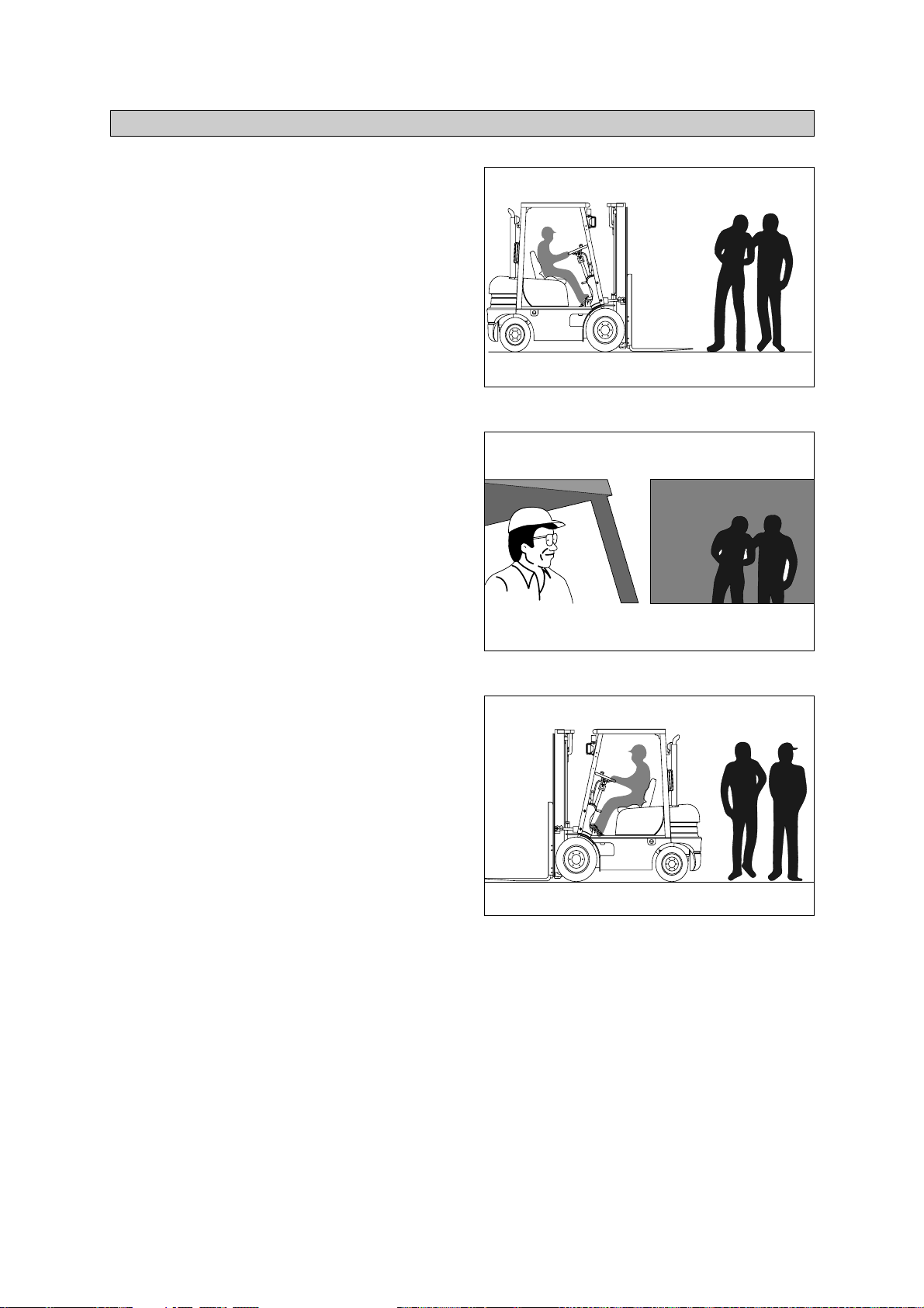
Watch where you are going. Look in the
direction of travel. Pedestrians may use the
same roadway you do. Sound your horn at
all intersections or blind spots.
D35AOM13
Watch for people in your work area even if
your truck has warning lights or alarms.
People may not watch for you.
D35AOM14
Watch for people standing back, even when
you are parked.
D35AOM15
5. PEDESTRIANS
1)
2)
3)
https://truckmanualshub.com/
Page 29

1-7
6. OPERATOR PROTECTION
D35AOM16
Keep under the overhead guard.
Always keep your body within the confines of
the truck.
Do not operate truck without overhead
guard, unless condition prevent use of a
guard.
1)
2)
https://truckmanualshub.com/
Page 30

1-8
Never allow anyone to walk under raised forks.
D255OM17A
There is special equipment to raise people for
overhead work.
DO NOT USE LIFT TRUCKS.
D255OM12A
Always lower the load slowly.
Raise and lower with mast vertical or tilted
slightly back(Never forward).
D255OM01
7. FORK SAFETY
https://truckmanualshub.com/
Page 31
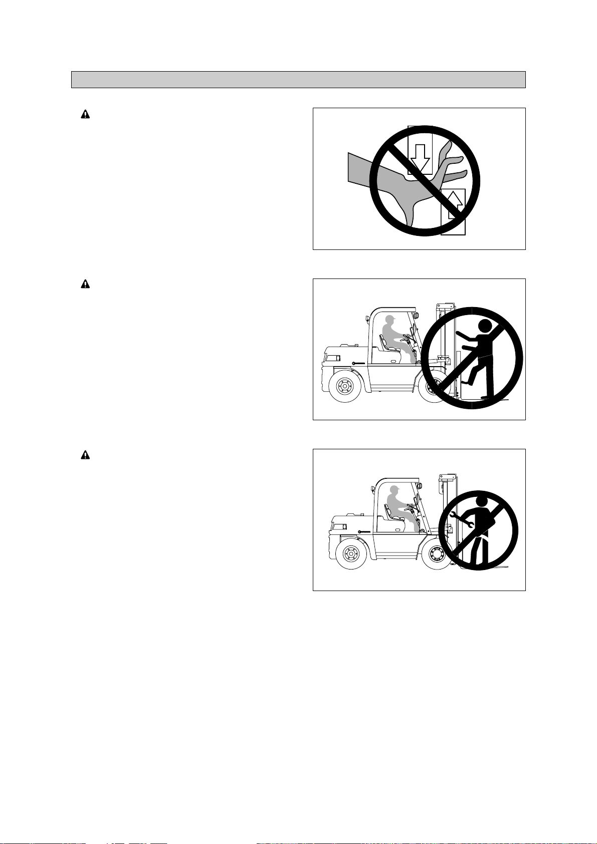
1-9
Keep hands, feet and legs out of the
mast.
D255OM61
Don't use the mast as a ladder.
D255OM62
Never try to repair the mast, carriage,
chain, or attachment by yourself. Always
get a trained mechani
c.
D255OM63
8. PINCH POINTS
https://truckmanualshub.com/
Page 32

1-10
Travel with the load near the floor/ground,
with mast tilted back to cradle the load
whenever possible.
Never lift or lower the load when the
truck is in motion.
D35AOM23
When handling bulky loads that restrict your
vision operate your truck in reverse to
improve visibility. Be sure to pivot in the
seat to give maximum visibility.
D255OM24A
Unstable loads are a hazard to you and to
your fellow workers. Always make certain
that the load is well stacked and evenly
positioned across both forks. Never
attempt to lift a load with only one fork.
Wrong
D255OM25A
9. TRAVEL
1)
2)
3)
https://truckmanualshub.com/
Page 33

1-11
10. GRADES, RAMPS, SLOPES AND INCLINES
D255OM26A
D255OM27A
Unloaded-Forks downgrade
Loaded - Forks upgrade
1)
2)
Never turn on a grade, either loaded or unloaded.
https://truckmanualshub.com/
Page 34

1-12
LATERAL TIP OVER
Lateral tip over can occur with a combination
of speed and sharpness of turn. This
combination will exceed the stability of the
truck. This condition is even more likely with
an unloaded truck.
With the load or mast raised, lateral tip over
can occur while turning and/or braking when
traveling in reverse or accelerating and
turning while traveling forward.
Lateral tip over can occur loaded or
unloaded by turning on an incline or ramp.
D35AOM28
LONGITUDINAL TIP OVER
Longitudinal tip over can occur with
combination of overloading and load
elevated also with capacity load and
elevated. This combination will exceed the
stability of the truck. This condition is even
more likely with excessive forward tilt,
braking in forward travel or accelerating
rearward.
Longitudinal tip over can occur by driving
with the load down slope on a steep grade.
Lateral and longitudinal tip over can occur if
the truck is driven over objects on the floor or
ground, off the edge of improved surfaces, or
into potholes in the road surface, or by running
into overhead objects or collisions.
An off dock type of tip over can occur if the
truck is steered too close to the dock edge,
driven off the edge of the dock or ramp, or if
the highway truck or trailer rolls away from the
dock or is driven away during loading.
The conditions listed above can be further
aggravated by overloading, exc
essive tilt,
or off center loads.
Lift truck tip over can cause serious injury
or death if the operator is trapped between
the truck and the ground.
D35AOM29
11. TIP OVER
1)
2)
(1)
(2)
(3)
(1)
(2)
https://truckmanualshub.com/
Page 35

1-13
WHAT TO DO IN CASE OF A TIP OVER
D35AOM30
3)
If your truck starts to tip over, do not
jump.
Brace yourself as illustrated right.
1. Make sure your seat belt is fastened
securely, if the truck is equipped with
seat belt.
2. Stay in your seat.
3. Grip the wheel.
4. Brace your feet.
Your chances for
survival in a tip-over
are better if you stay with the truck, in
your seat.
3
1
2
4
https://truckmanualshub.com/
Page 36

1-14
12. SURFACE AND CAPACITY
TIPOVER
Seat belts can reduce injuries.
ALWAYS BUCKLE UP.
D35AOM31
B207OM10
Avoid these conditions. They can cause a
truck to tip over or lose traction for braking or
driving.
Know the weight of your truck and load.
Especially when using elevators, know
the capacity of the ele
vator you intend to
use. Do not overload.
https://truckmanualshub.com/
Page 37

1-15
Never park on a grade.
D35AOM33
Always come to a complete stop before
leaving truck. Be sure travel control is in
NEUTRAL.
D35AOM34
Lower forks fully to floor and tilt forward.
OFF
ON
START
2
1
D255OM35A
Set parking brake.
Position 1 : Lock
Position 2 : Release
Turn key to OFF position.
13. PARKING
1)
2)
3)
4)
5)
20D7OM24
https://truckmanualshub.com/
Page 38

1-16
Before adding oil, check around machine
for oil leakage.
D255OM02
Keep away from fire when adding oil or
during operation.
DIESEL
D255OM03
After adding oil, wipe off any oil spilled on
machine.
D255OM04
14. REFUELING
1)
2)
3)
https://truckmanualshub.com/
Page 39

1-17
When getting on or off the machine, use the
step provided.
D255OM05
Do not jump up or down from the machine.
D255OM06
15. STEP
1)
2)
https://truckmanualshub.com/
Page 40

Traction safety warning
This function works when the key switch is ON or START position.
The transmission shifts automatically to neutral in 2 seconds from the driver's off the seat.
At the same time, the alarm will sound intermittently.
To release the function, the forward-reverse lever must be cycled through neutral with the
operator in the normal operating position to regain powered directional control.
1-18
All operational functions require that the
operator be seated in the operator's seat.
Alwa y s buc k le up if a seat belt is
provided.
D35AOM23
Parking brake must be locked in the PARK
POSITION before exiting from the vehicle.
Parking brake must remain locked in the
park position(2) except when an operator
is in the normal ope
rating position.
2. Lock(Park)
1. Release(Drive)
D507OM24
16. OPERATOR'S SAFETY RULES
1)
2)
ANSI/ASME REGULATIONS (
USA ONLY
)
This forklift truck is equipped with an Operator Existence Sensing System per ANSI/ASME
B56.1 ~ 7.21.10 and 7.21.11.
3)
(1)
Η
Θ
Ι
Κ
https://truckmanualshub.com/
HYUNDAI
Page 41

2-1
Loose or unbalanced loads are dangerous.
Observe these precautions.
Never carry loose or uneven material.
2. OPERATING HAZARDS
1. LOOSE LOADS
D255OM39
Center wide loads.
D35AOM40
Stack and band loose material.
D35AOM41
Avoid sudden braking or starting
When the machine is loaded, do not
drive at maximum speed.
D255OM07
https://truckmanualshub.com/
Page 42

2-2
With long or wide loads, you need more
room. So slow down and watch your
clearance.
When extra-long material makes it
necessary to travel with the load elevated,
do so with extreme care and be alert to
load end-swing when turning.
A long load redu
ces the capacity of the
truck. Know and understand your truck
load rating.
2. LONG AND WIDE LOADS
D35AOM42
When turning, be sure the rear end of
the truck doe s not swing into racks,
posts, etc. Watch for pedes
trians beside
the truck.
3. REAR SWING
D255OM43
https://truckmanualshub.com/
Page 43

2-3
Know the height of your truck, with and
without a load. Check your clearances.
Keep the load low and
tilted back.
4. LOW OVERHEAD CLEARANCE
B207OM44
Watch overhead clearance:
Moving into overhead structures can tip
a truck over, or spill a load.
B207OM45
Slow down before turning.
The truck can tip over.
D255OM46
Turn too sharp with a raised load and
your truck can tip even at slow speeds.
Travel with a load raised
only when
removing or depositing a load.
D255OM07
5. FAST TURNS AND HIGH LOADS
https://truckmanualshub.com/
Page 44

2-4
To avoid these hazards, you must:
Talk to the truck driver yourself: make sure
the driver does not move the trailer until you
are done.
Apply trailer brakes.
Use wheel chocks.
Use trailer-to-dock locking system if
available.
The impact of moving in and out of a
trailer may cause the trail
er to creep or
move.
D35AOM48
D35AOM49
6. DROP-OFFS
When right angle stacking or moving with
a raised load to clear low objects, avoid
sharp turns and move
slowly.
7. RIGHT ANGLE STACKING
D35AOM50
1)
2)
3)
4)
https://truckmanualshub.com/
Page 45

2-5
Slack chains mean rail or carriage hangup.
Raise the forks before you move, or
broken chains can resu
lt.
In case forks with loads are stuck while
lowering the mast, lift the mast again and
prevent chains f
rom being slack.
8. CHAIN SLACK
D35AOM51
D35AOM52
Do n o t move o r store material s on
damaged pallets or skids. Items can fall
through them causing severe
injury or
death.
Be sure the pallet or skid you are using
is in good condition and does not have
defecti
ve or missing components and
fasteners.
9. PALLETS AND SKIDS
D35AOM53
https://truckmanualshub.com/
Page 46

2-6
When moving the machine with the mast
raised, watch out electrical lines over the
machine.
The operatin
g near the electrical lines is
very dangerous.
Operate within safe working permitted as
below.
10. CAUTION FOR ELECTRICAL LINES
D255SF01
D255SF02
If the machine touches the electric power
lines, keep sitting on the operator’s seat
and make sure the
pers o nnel on the
ground not to touch the machine until
turning off the electric current.
Jump off the ma
chine without contacting
the machine when you need to get off.
Supply voltage
6.6 kV
33.0 kV
66.0 kV
154.0 kV
275.0 kV
Min safe separation
3m(10 ft)
4m(13 ft)
5m(16 ft)
8m(26 ft)
10m(33 ft)
https://truckmanualshub.com/
Page 47

2-7
Never permit any persons to stand or
pass under lifted load.
11. LIFTING LOADS
D255OM08
D255OM09
Never use wire rope to lift a load.
Never operate the side shift while the forks
are not equipped with supports such as a
load table for the load.
Never travel the fork lift while the side
shift is moved with load.
In case of moving the side shift with load,
it can be caused load dropping or
overturning of the fork lift due to
unbalanced weight.
The fork lift can be overturned due to the
unbalanced load.
35D7EOM61
12. SIDE SHIFT
https://truckmanualshub.com/
Page 48

2-8
It should be observed that the side shift
with load is operated in netural position
before traveling.
When operating side shift with load,
operate slowly so that it can not avoid
from dropping of the load or overturning
of the fork lift.
35D7EOM63
Never move the load to push or pull of it by
the side shift.
It can be caused damaging of the loads or
injuring of the people.
35D7EOM62
While traveling the fork lift with the load on
the side shift, if the operator lift or lower the
load without shifting it in the netural position,
it can be overturned the fork lift due to
unstabled load.
When lifting or lowering the side shift with
load, it should be observed that the load is
moved into the netural position.
35D7EOM64
https://truckmanualshub.com/
Page 49

2-9
Do not operate the fork positioner with a
load, or with the fork arm on the ground.
Never move the levers to operate the
pork positioner suddenly and quickly.
It can be caused to drop
the load.
35D7EOM65
13. FORK POSITIONER
https://truckmanualshub.com/
Page 50

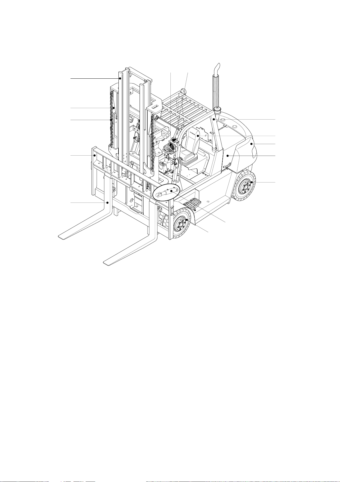
3-1
3. KNOW YOUR TRUCK
1. GENERAL LOCATIONS
1 Mast
2 Lift chain
3 Lift cylinder
4 Backrest
5 Tilt cylinder
6 Lift bracket
7Forks
8 Overhead guard
9 Turn signal lamp
10 Head lamp
11 Operator's seat
12 Bonnet
13 Counterweight
14 Rear wheel
15 Front wheel
16 Rear combination lamp
9
10
1
2
4
6
7
15
5
14
12
13
16
11
8
3
15D7EOM54
15D/18D/20DA-7E
1)
https://truckmanualshub.com/
Page 51

3-2
1 Mast
2 Lift chain
3 Lift cylinder
4 Backrest
5 Tilt cylinder
6 Lift bracket
7Forks
8 Overhead guard
9 Turn signal lamp
10 Head lamp
11 Operator's seat
12 Bonnet
13 Counterweight
14 Rear wheel
15 Front wheel
16 Rear combination lamp
1
2
3
4
5
6
7
15
9
16
8
11
10
13
12
14
20D7OM01
20D/25D/30D/33D-7E, 20DF/25DF/30DF/33DF-7, 35DF-7
2)
https://truckmanualshub.com/
Page 52

3-3
1 Mast
2 Lift chain
3 Lift cylinder
4 Backrest
5 Tilt cylinder
6 Lift bracket
7Forks
8 Overhead guard
9 Turn signal lamp
10 Head lamp
11 Operator's seat
12 Bonnet
13 Counterweight
14 Rear wheel
15 Front wheel
16 Rear combination lamp
4
6
7
1
2
3
15
5
14
12
13
16
11
8
10
9
35DS7EOM54
35D/40D/45D-7E, 50D-7AE, 35DS/40DS/45DS/50DA-7E
3)
https://truckmanualshub.com/
Page 53

3-4
1 Mast
2 Lift chain
3 Lift cylinder
4 Backrest
5 Tilt cylinder
6Forks
7 Overhead guard
8 Turn signal lamp
9 Head lamp
10 Operator's seat
11 Bonnet
12 Counterweight
13 Rear wheel
14 Front wheel
15 Rear combination lamp
4
6
1
2
3
14
5
9
13
11
12
7
10
8
15
50DEOM54
50D/60D/70D-7E, 80D-7E
4)
https://truckmanualshub.com/
Page 54

3-5
1 Mast
2 Lift chain
3 Lift cylinder
4 Backrest
5 Tilt cylinder
6 Lift bracket
7Forks
8 Overhead guard
9 Turn signal lamp
10 Head lamp
11 Operator's seat
12 Bonnet
13 Counterweight
14 Rear wheel
15 Front wheel
16 Rear combination lamp
4
6
7
1
2
3
15
5
14
12
13
16
11
8
10
9
50DS7EOM54
50DS/60DS/70DS-7E
5)
https://truckmanualshub.com/
Page 55
3-6
1 Mast
2 Lift chain
3 Lift cylinder
4 Backrest
5 Tilt cylinder
6Forks
7 Overhead guard
8 Turn signal lamp
9 Head lamp
10 Operator's seat
11 Bonnet
12 Counterweight
13 Rear wheel
14 Front wheel
15 Rear combination lamp
6
4
2
3
98
7
10
12
11
13
5
14
1
60DF7CM54
50DF/60DF/70DF-7
6)
https://truckmanualshub.com/
Page 56

3-7
1
2
3
5
4
TRUCK DATA AND CAPACITY PLATE
Truck model number or registered name
Truck serial number
An identification number assigned to this particular truck and should be used when requesting
information or ordering service parts for this truck from your authorized HYUNDAI dealer. The
serial number is also stamped on the frame.
Attachment des
cription(If any installed)
The user must see that the truck is marked to identify the attachment(s), including the weight of
the truck/attachment combination and truck capacity with the attachment.
Capacity rating, load center, and lifting height data
Shows the maximum load capacity of this truck with relation to load centers and fork heights(See
diagram on plate). Personal injury and damage to the truck can occur if these capacities are
exceeded.
Do not exceed the
maximum capacity specified.
Truck weight
The approximate weight of the truck without a load on the forks. This weight plus the weight of the
load must be considered when operating on elevators, elevated floors, etc. to be sure they are
safe.
Before modifications that affect the stability of safety sy
stems are made written approval
from HYUNDAI. This is an OSHA requirement. Contact your authorized HYUNDAI dealer
for a new nameplate showing the revised capacity.
1)
(1)
(2)
(3)
(4)
(5)
D255OM56
2. DATA/SAFETY PLATES AND DECALS
https://truckmanualshub.com/
Page 57

3-8
Safety and warning decals are placed in conspicuous locations on the
truck to remind you of essential procedures or to prevent you from
making an error that could damage the truck or possibly cause personal
injury. You should know, understand, and follow these instructions.
Safety and warning decals. Should be replaced immediately if missing
or defaced(Damaged or illegible). Refer to your Service manual for the
location of all decals.
Operator/Tip-over warning decal
This decal is located on the front right hand leg of the drivers overhead. Its
purpose is to remind the operator that staying in the seat provides the best
chance of avoiding injury in the event of a truck-tipping or driving off a dock
mishap.
Lift trucks can be tipped over if operated improperly. Experience with lift truck
accidents has shown that the driver cannot react quickly enough to jump
clear of the truck and overhead guard as the truck tips. To protect operators
from severe injury or death in the event of a tip over, it is best to be held
securely in the seat. So, please, always buckle up when driving your lift
truck.
15D/18D/20DA, 20D/25D/30D/33D ONLY
15DEOM59K
25L7AOM09
%%%"&%%%%&0/-:
OPERATOR SAFETY WARNING DECAL
2)
https://truckmanualshub.com/
Page 58
3-9
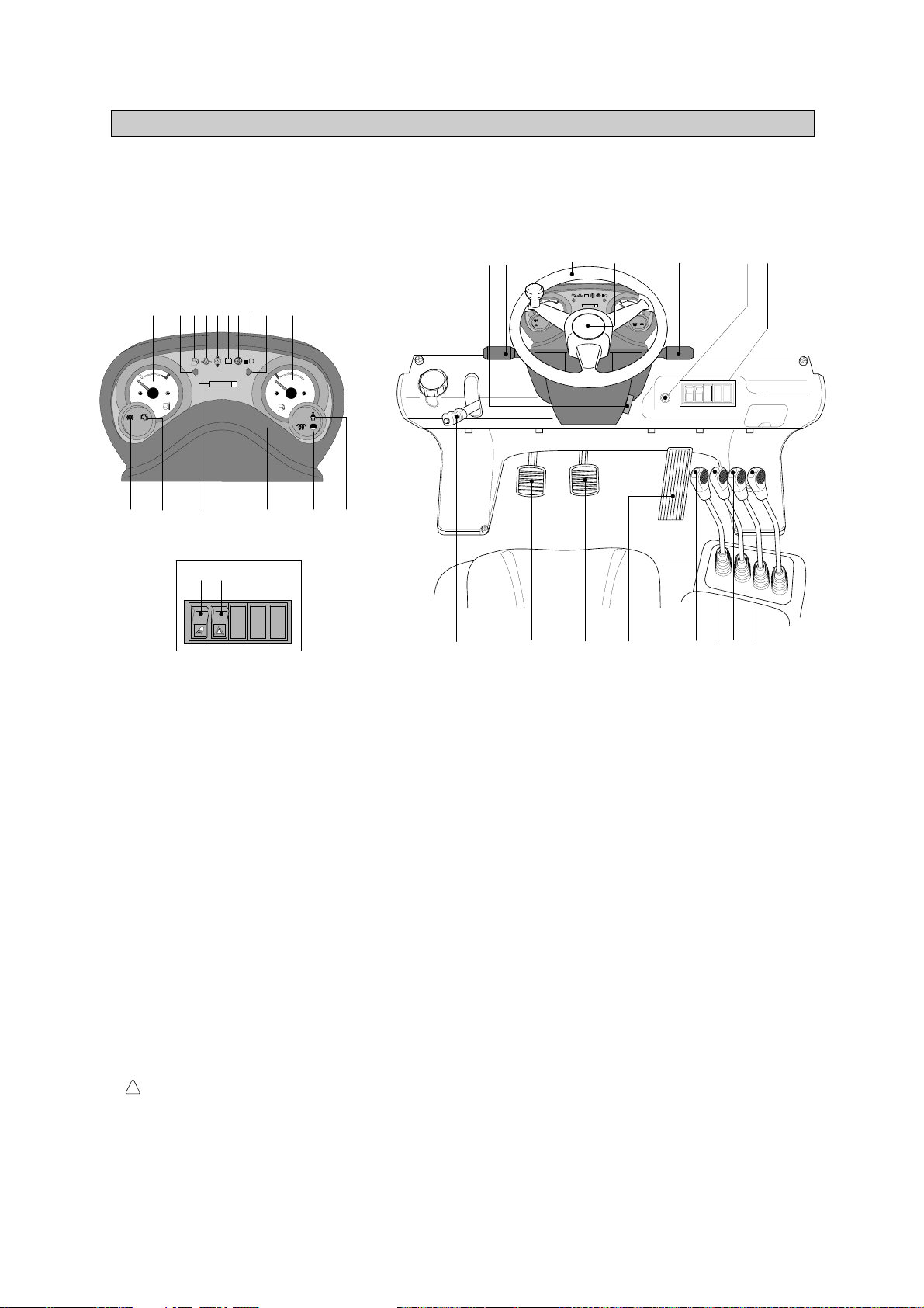
3. INSTRUMENTS AND CONTROLS
DETAIL A
HYUNDAI
H
E
F
000000
C
LPG
+
-
17
18
19
1
234578910
11
1213
14 15 16
A
20 21 22 24 25 26 27
32
28
3334
23
6
HYUNDAI
H
E
F
000000
C
+
-
29,30,31
15D7EOM641
Familiarize yourself with the controls and follow safe operating procedures.
15D/18D/20DA-7E
1)
1 Start switch
2 Water temperature gauge
3 Left turn signal lamp
4 Fuel level warning lamp
5 Engine oil pressure warning lamp
6 Battery charge warning lamp
7 T/M oil temp warning lamp
8 Air cleaner element warning lamp
9 Head lamp signal lamp
10 Right turn signal lamp
11 Fuel gauge
12 Engine check lamp
13 Parking brake signal lamp
14 Hour meter
15 Preheater signal lamp
16 Water separator lamp
17 Work lamp switch(opt)
18 Hazard lamp switch(opt)
19 Seat belt warning lamp
20 Parking brake lever
21 Inching pedal
22 Brake pedal
23 Accelerator pedal
24 Lift lever
25 Tilt lever
26 Attach lever 1(opt)
27 Attach lever 2(opt)
28 Horn button
29 Head lamp switch
30 Illumination lamp
31 Turn signal switch
32 Steering wheel
33 Forward-reverse lever
34 Steering column adjust
lever
https://truckmanualshub.com/
Page 59

3-10
DETAIL A
HYUNDAI
H
E
F
000000
C
LPG
+
-
17
18
19
1
234578910
11
1213
14 15 16
A
20 21 22 24 25 26 27
32
28
3334
23
6
HYUNDAI
H
E
F
000000
C
+
-
29,30,31
15D7EOM641
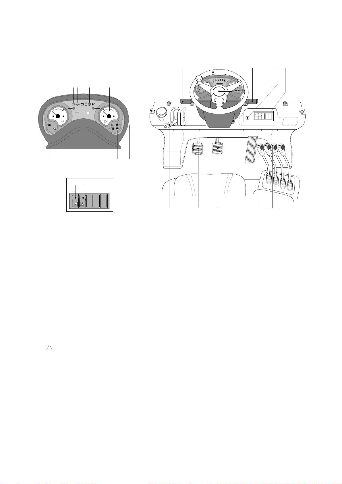
Familiarize yourself with the controls and follow safe operating procedures.
20D/25D/30D/33D-7E, 20DF/25DF/30DF/33DF-7, 35DF-7
2)
1 Start switch
2 Water temperature gauge
3 Left turn signal lamp
4 Fuel level warning lamp
5 Engine oil pressure warning lamp
6 Battery charge warning lamp
7 T/M oil temp warning lamp
8 Air cleaner element warning lamp
9 Head lamp signal lamp
10 Right turn signal lamp
11 Fuel gauge
12 Engine check lamp
13 Parking brake signal lamp
14 Hour meter
15 Preheater signal lamp
16 Water separator lamp
17 Work lamp switch(opt)
18 Hazard lamp switch(opt)
19 Seat belt warning lamp
20 Parking brake lever
21 Inching pedal
22 Brake pedal
23 Accelerator pedal
24 Lift lever
25 Tilt lever
26 Attach lever 1(opt)
27 Attach lever 2(opt)
28 Horn button
29 Head lamp switch
30 Illumination lamp
31 Turn signal switch
32 Steering wheel
33 Forward-reverse lever
34 Steering column adjust
lever
https://truckmanualshub.com/
Page 60
3-11
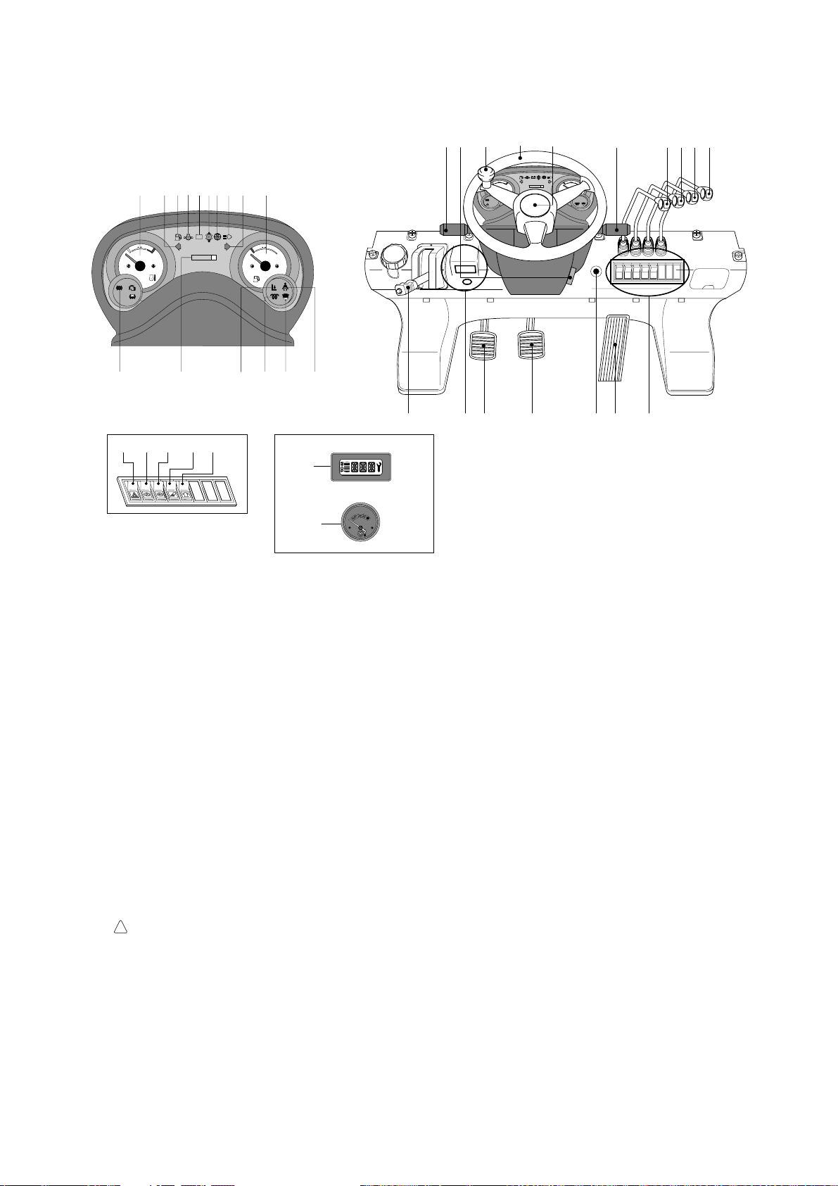
1 Start switch
2 Water temperature gauge
3 Left turn signal lamp
4 Fuel level warning lamp
5 Engine oil pressure warning lamp
6 Battery charge warning lamp
7 T/M oil temp warning lamp
8 Air cleaner element warning lamp
9 Head lamp signal lamp
10 Right turn signal lamp
11 Fuel gauge
13 Parking brake signal lamp
14 Hour meter
15 Preheater signal lamp
16 Water separator lamp
17 Work lamp switch(opt)
18 Hazard lamp switch(opt)
19 Seat belt warning lamp
20 Parking brake lever
21 Inching pedal
22 Brake pedal
23 Lift lever
24 Tilt lever
25 Attach 1 lever(opt)
26 Attach 2 lever(opt)
27 Horn button
28 Head lamp switch
29 Illumination lamp
30 Turn signal switch
31 Steering wheel
32 Forward-reverse lever
33 Steering column adjust lever
34 Operator safety lamp(OPSS)
DETAIL A
HYUNDAI
H
E
F
000000
C
LPG
+
-
17
18
19
1
2345 8910
11
13
14 15 16
A
20 21 22 23 24 25 26
31
27
32 33
HYUNDAI
H
E
F
000000
C
28,29,30
76
+
-
34
35DS7EOM64T
Familiarize yourself with the controls and follow safe operating procedures.
35D/40D/45D-7E, 50D-7AE, 35DS/40DS/45DS/50DA-7E
3)
https://truckmanualshub.com/
Page 61

3-12
1 Start switch
2 Water temperature gauge
3 Left turn signal lamp
4 LCD
5 Right turn signal lamp
6 Fuel gauge
7 Parking brake signal lamp
8 Fuel level warning lamp
9 Engine oil pressure warning lamp
10 T/M oil temp warning lamp
11 Battery charge warning lamp
12 Air cleaner element warning lamp
13 Head lamp signal lamp
14 Work lamp signal lamp
15 Preheater signal lamp
16 T/M display
17 T/M temperature gauge
18 Parking brake lever
19 Forward-reverse lever
20 Head lamp switch
21 Clearance lamp switch
22 Multi function switch
23 Washer switch
24 Lift lever
25 Tilt lever
26 Attach 1 lever(opt)
27 Attach 2 lever(opt)
28 Attach 3 lever(opt)
29 Full automatic switch
30 Clutch cutoff switch
31 Work lamp switch
32 Beacon lamp switch(opt)
33 Inching pedal
34 Brake pedal
35 Accelerator pedal
36 Steering wheel
37 Steering wheel
knob
38 Engine check lamp
39 Brake fail warning lamp
40 T/M error warning lamp
41 Water separator lamp
42
Engine coolant
temperature warning lamp
43 Seat belt warning lamp
44 OPSS lamp
45 Inching pilot lamp
46 Speed meter
47 Hazard lamp switch
48 Wiper switch
49 Buzzer stop button
50 Cabin tilt switch
51 Air conditioner controller
26 27 282524
A
47
30
29
31
32
48
23
19
33
35
34
20,21,2236
1
15 38 46 4 49 17 8 6 2
14
74210513339
40
9
41
43
44
11
45
12
16
18
37
CABIN TILT SWITCH
51
50
50DEOM64
50D/60D/70D-7E, 80D-7E
4)
Familiarize yourself with the controls and follow safe operating procedures.
https://truckmanualshub.com/
Page 62
3-13
1 Start switch
2 Water temperature gauge
3 Left turn signal lamp
4 Fuel level warning lamp
5 Engine oil pressure warning lamp
6 Battery charge warning lamp
7 T/M oil temp warning lamp
8 Air cleaner element warning lamp
9 Head lamp signal lamp
10 Right turn signal lamp
11 Fuel gauge
13 Parking brake signal lamp
14 Hour meter
15 Preheater signal lamp
16 Water separator lamp
17 T/M display
18 T/M temperature gauge
19 Seat belt warning lamp
20 Parking brake lever
21 Forward-reverse lever
22 Head lamp switch
23 Clearance lamp switch
24 Turn signal switch
25 Horn button
26 Lift lever
27 Tilt lever
28 Attach 1 lever(opt)
29 Attach 2 lever(opt)
30 Hazard lamp switch
31 Full automatic switch
32 Inching switch
33 Work lamp switch
34 Beacon lamp switch(opt)
35 Inching pedal
36 Brake pedal
37 Accelerator pedal
38 Steering wheel
39 Steering wheel
knob
40 Steering column adjust lever
41 OPSS lamp
HYUNDAI
H
E
F
000000
C
LPG
+
-
HYUNDAI
H
E
F
000000
C
+
-
30
31
32 33
DETAIL A
34
DETAIL B
OIL TEMP
17
18
A
B
37
20
2140 38 25 26272829
35 36
22,23,24
19
2345 8910
11
13
14 15 16
76
41
39
1
50DS7EOM64
50DS/60DS/70DS-7E
5)
Familiarize yourself with the controls and follow safe operating procedures.
https://truckmanualshub.com/
Page 63

3-14
1 Start switch
2 Water temperature gauge
3 Left turn signal lamp
4 Fuel level warning lamp
5 Engine oil pressure warning lamp
6 Battery charge warning lamp
7 T/M oil temp warning lamp
8 Air cleaner element warning lamp
9 Head lamp signal lamp
10 Right turn signal lamp
11 Fuel gauge
13 Parking brake signal lamp
14 Hour meter
15 Preheater signal lamp
16 Water separator check lamp
17 Work lamp switch(opt)
18 Hazard lamp switch(opt)
19 Beacon switch
20 Parking brake lever
21 Inching pedal
22 Brake pedal
23 Lift lever
24 Tilt lever
25 Attach 1 lever(opt)
26 Attach 2 lever(opt)
27 Horn button
28 Head lamp switch
29 Illumination lamp
30 Turn signal switch
31 Steering wheel
32 Forward-reverse lever
33 Steering column adjust lever
35 Engine check lamp (STD)
36 Operator safety lamp (OPT)
P
13 4 5 7 6 8
31421011
20
28
32
A
16
36
18
17
DETAIL A
91715
23
24 25 26
1
21 22
31
19
,29,30
33
27
35
60DF7EOM64T
Familiarize yourself with the controls and follow safe operating procedures.
50DF/60DF/70DF-7
6)
https://truckmanualshub.com/
Page 64
3-15
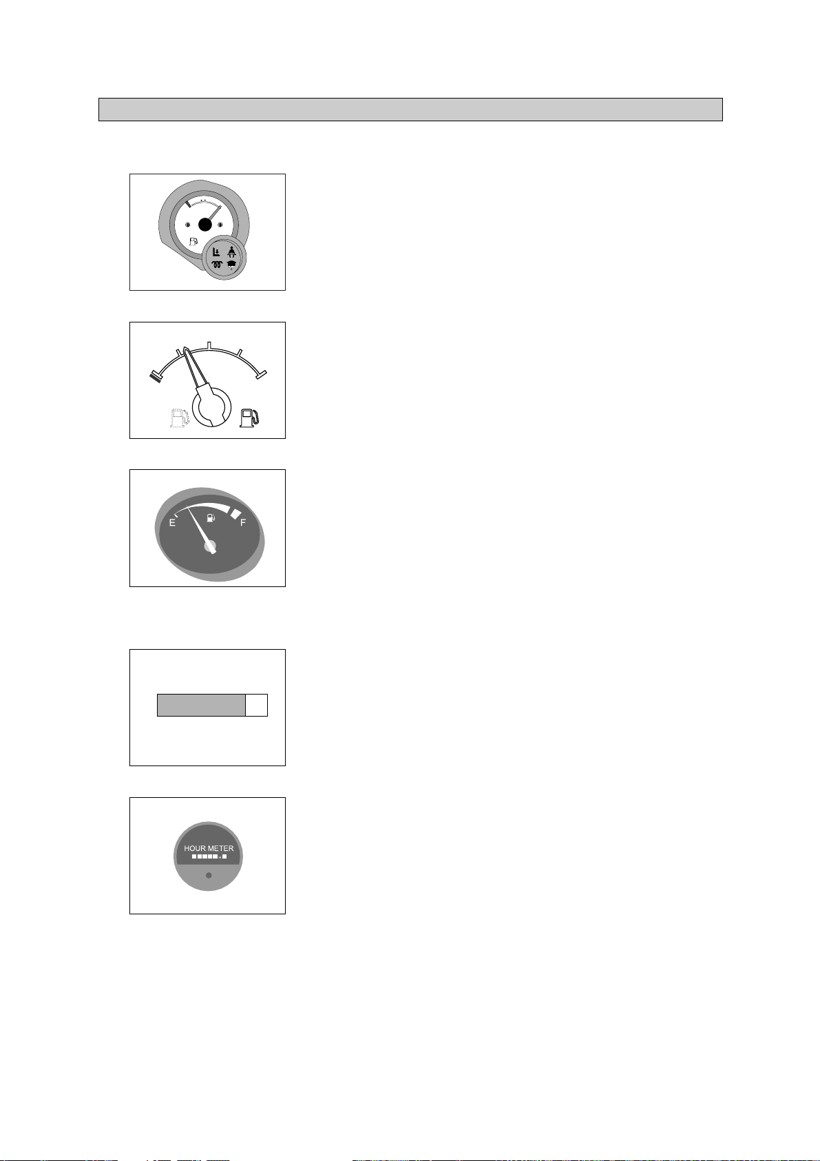
E
: Empty
F
: Full
Fill fuel tank regularly.
Never allow machine to run out fuel.
Do not overfill the fuel tank.
Always check the fuel level on level ground.
FUEL GAUGE
1)
This indicates the time of total machine operation.
All service intervals for periodic maintenance are based on
service meter readings.
The last digit advances by 1/10 hours.
50D/60D/70D-7E, 80D-7E : Refer to page 3-19.
HOUR METER
2)
4. INDICATOR SYMBOLS
(1)
(2)
(3)
ö
(1)
ö
(2)
ö
00000
0
15D7EOM02K
60DFOM10K
15D7EOM10K
E
F
1/2
160D7ECD04
%%%&%&
60DFOM02K
%'%'%'
%'%'%'
F
E
https://truckmanualshub.com/
Page 65

3-16
The indicator shows the engine cooling water temperature.
White range : Normal
Red range : Danger of overheating.
Action to take if indicator enters red range.
Stop operations immediately and move the truck to a safe
place.
Open the engine hood to improve the ventilation and run the
engine at low idling until the temperature drops to the white
range.
For details, see HANDLING MACHINE IN EXTREMELY
HOT PLACES, page 7-55.
WATER TEMPERATURE GAUGE
3)
C
H
Red
160D7ECD10
%%%&%&
H
C
15D7EOM03K
(1)
Η
Θ
Η
Θ
(2)
ö
60DFOM03K
This range indicates the temperature of transmission oil.
Â
White range : 40-107ÁC
(104-225ÁF
)
Â
Red range : 107ÁC
(225ÁF
) above
The white range indicates when operating.
Keep idling engine at low speed until the white range
indicates, before operation of machine.
If the indicator is in the red range, it means the transmission
is overheated. Be careful that the indicator does not move
into the red range.
TTRANSMISSION OIL TEMPERATURE GAUGE
(1)
(2)
4)
C
H
Red
160D7ECD11
%4%4%4&
%%%&%&
Η
Θ
This lamp informs the operator that transmission oil is above
the specified temperature.
Transmission oil temperature warning lamp ON : Abnormal
Transmission oil temperature warning lamp OFF : Normal
W
When this lamp lights up during operation, stop the engine
and check the machine.
TRANSMISSION OIL TEMP
ERATURE WARNING LAMP (1.5~4.5 ton, 50~70DF-7)
5)
D35AOM79
(1)
Η
Θ
ö
%'%'%'
https://truckmanualshub.com/
Page 66

This lamp informs the operator that fuel in the tank is below the
specified level. And this lamp prevents the engine from
stopping suddenly. This lamp is installed separate from the fuel
gauge.
If this lamp lights up, stop the engine and refill the fuel
immediately.
FUEL LEVEL WARNING LAMP
(1)
ö
99)
D35AOM83
This lamp lights up when the replacement time of element is
late and the element is dirty, so air influx is not smooth.
If this lamp lights up, clear the element or replace it.
AIR CLEANER ELEMENT WARNING LAMP
(1)
ö
D35AOM84
10)
This lamp shows that the alternator is not generating electricity.
When the starting switch is turned ON, the lamp will lights
up, but it should go out after the engine starts.
If the lamp lights up during operation, stop the engine and
check the fan belt tension and the electrical system.
BATTERY CHARGE WARNING LAMP
(1)
ö
ö
8
8)
3-17
This lamp lights up when key is turned to ON position. After a
while the heater signal lamp goes out, then turn the key to
START position.
PRE HEATER SIGNAL LAMP
(1)
6)
D35AOM80
This lamp informs the operator that the engine oil pressure is
below the specified level.
This lamp lights when starting switch is turned ON and goes
out when oil pressure becomes normal.
Immediately stop operation if this lamp lights up during
operation. Stop the engine and check the
machine if
necessary.
ENGINE OIL PRESSURE WARNING LAMP
(1)
(2)
ö
77)
D35AOM81
15D7EOM82K
+
-
https://truckmanualshub.com/
Page 67

3-18
This lamp shows that the head lamp lights up or not.
Head lamp lights up : Signal lamp lights up.
Head lamp goes out : Signal lamp goes out.
HEAD LAMP SIGNAL LAMP
(1)
11)
Η
Θ
D35AOM85
This lamp shows that the working lamp lights up or not.
Working lamp lights up : Signal lamp lights up.
Working lamp goes out : Signal lamp goes out.
WWORKING LAMP SIGNAL LAMP
(1)
12)
Η
Θ
D35AOM86
Right turn signal lamp flickers when pulling on the turn signal
lever.
R
RIGHT TURN SIGNAL LAMP
(1)
14)
D35AOM88
This lamp shows that the parking brake is applied or not.
Parking brake locked : Signal lamp lights up.
Parking brake unlocked : Signal lamp goes out.
Make sure that the signal lamp goes out before operating the
machine.
PARKING BRAKE SIGNAL LAMP
(1)
15)
P
D35AOM901
Η
Θ
Left turn signal lamp flickers when pushing on the turn signal
lever.
L
LEFT TURN SIGNAL LAMP
(1)
13)
D35AOM87
(2)
https://truckmanualshub.com/
Page 68

3-19
This lamp lights up when the water separator is full of water or
malfunctioning.
When this lamp lights up, stop the machine and spill water
out of the separator.
WATER SEPARATOR LAM
P
(1)
ö
116)
D357OM902
This lamp lights ON and alarm sounds for the first 3 seconds
after starting the truck.
SEAT BELT WARNING LAMP
(1)
19)
D357OM906T
This signal lamp lights ON when the operator leaves the seat.
Powered travel movement of the truck shall be possible only if
the operator is in the normal operating position. Transmission
will automatically shift to neutral upon the exiting of the
operator.
The forward/Reverse lever must be cycled through neutral with
the operator in the normal operating position to regain powered
direction control.
OPERATOR SAFETY LAMP
35D/40D/45D-7E, 50D-7AE, 50D/60D/70D-7E, 80D-7E OPSS equipped
(1)
(2)
(3)
18)
D357OM905T
This lamp lights ON during a nonfatal engine system error. The
engine can steel be run, but the fault should be corrected as
soon as possible.
If the engine check lamp is lighted up, stop and park the
machine, and then consult with the service
center or
Hyundai dealer at once.
ENGINE CHECK LAMP
(1)
ö
17)
D357OM904T
https://truckmanualshub.com/
Page 69

3-20
The lamp lights ON when the oil pressure of service brake drops
below the normal range.
When the lamp is ON, stop the engine and check for its cause.
Do not operate until any problems are corrected.
(1)
(2)
ö
BRAKE FAIL WARNING LAMP
20)
This lamp is turned ON when the temperature of cooling water is
over the normal temperature(104ÁC, 219ÁF).
Check the cooling system when the lamp is ON.
(1)
(2)
ENGINE OVERHEAT WARNING LAMP
21)
77073CD16
77073CD17
FUEL LOW LEVEL WARNING LAMP
22)
Fill the fuel immediately when the lamp is turned ON.
(1)
77073CD23
https://truckmanualshub.com/
Page 70

3-21
Each button has the following function.
Buzzer stop button
Next button
MENU button
160D7ECD121E
This switch is used to stop the buzzer sound.
Stop the buzzer when the switch is pressed.
Η
Θ
160D7ECD22
160D7ECD24
This switches are used to choose the model.
Model select mode
The model is displayed on the LCD when the menu button
and next button are pressed simultaneously for some
longer seconds.
Please don't change your truck model identity because it is
already pre-set on th
e truck before delivery.
Η
Θ
ö
160D7ECD23
BBuzzer stop button
(1)
Menu and next button
(2)
CLUSTER BUTTON
(50D/60D/70D-7E, 80D-7E)
23)
https://truckmanualshub.com/
Page 71

3-22
LCD has the functions to display start mode, standby mode and model select.
LCD
(50D/60D/70D-7E, 80D-7E)
24)
Display initialization state with HYUNDAI logo and program version.
Η
160D7ECD25
START MODE DISPLAY
(1)
Displays rpm
Odometer
Hourmeter
Η
Θ
Ι
50DECD33
SSTANDBY MODE DISPLAY
(2)
On model select mode, displays like this image.
Refer to the page 3-21.
Η
ö
50DECD35
MMODEL SELECT DISPLAY
(3)
Η
Θ
Ι
https://truckmanualshub.com/
Page 72

3-23
TRANSMISSION ERROR DISPLAY
(
5.0 ~ 8.0
ton
: ZF Transmission)
Function
The display can be used with the gear selector(DW-3). It indicates speed and driving direction as
well as the activated kickdown.
When driving in the automatic mode, a bar indicator gives additionally also information about the
selected driving range; The automatic range is symbolized by arrows above and below the bar
indicator. In case of possible errors in the system, a wrench appears on the display, combined
with indication of the error number. Also sporadically occurring errors can be indicated.
25)
(1)
S
T
O
P
h
f
a
ed
bc
Left side
Central side
Right side
g
1
2
3
4
5
Bars
Left side
Central and
Right side
Spanner
Letters
STOP
a, f
b, c, d, e
g
h
Automatic range(up and down shifting)
Preselected gear
For the moment still without function
On the two alphanumeric 16-segment display, the electric control
unit issues the actual state of gear and driving direction. Besides,
a two digit error code will be indicated via these two segment
Electronic control unit recognized an error, is flashing
Immediate stop is required(At the moment not activated)
7803A3CD33
If it happens error codes, consult with Hyundai service center to repair the fault.
ö
https://truckmanualshub.com/
Page 73

3-24
Symbol Meaning
Actual gear and direction
Central side shows actual gear
Right side shows actual direction
Not neutral, waiting for neutral
after power up or a severe fault
Manual mode lst gear
Manual mode 2nd gear
Manual mode 3nd gear
Automatic mode
Kick down mode active
Transmission neutral
Downshift mode active
At least on fault active
Warning torque converter
temperature
Warning sump temperature
Warning high engine speed
Direction F or R selected while
parking brake engaged
Direction F or R selected while
turbine speed is to high
No communication with display
Remarks
To engage a gear, first move shift selector to
neutral position and again to F to R position
a, f
Cold start phase
Transmission in neutral until parking brake is
released.
Machine starts to move after release of
parking brake.
ö Gear will engage when turbine speed drops
Select neutral to get fault code displayed
Changes between actual gear/direction while
driving, in neutral only displayed if no fault is
detected(spanner)
Changes between actual gear/direction while
driving, in neutral only displayed if no fault is
detected(spanner)
Changes between actual gear/direction while
driving, in neutral only displayed if no fault is
detected(spanner)
DDisplay during operation
(2)
F, N, R
1, 2, 3
NN
(Central and right side)
1 bar
2 bar
3 bar
4 bars and 2 arrows
Arrows(a, f) flashing
Bars flashing
Spanner flashing
WT
WS
WE
PN
F or R flashing
EE flashing
(central and right side)
ö
https://truckmanualshub.com/
Page 74

3-25
Definition of the error codes
Introduction
The error codes consists of two hexadecimal numbers.
The first number shows the type of signal, the second number shows signal and the type of the
error.
Description of error codes
(3)
ΗΗ
Θ
First No.
1 hex
2 hex
3 hex
4 hex
7 hex
8 hex
9 hex
A hex
B hex
D hex
E hex
F hex
Meaning of number
Digital input signals
Analog input signals
Speed signals
Speed signals
Analog current output signals
Analog current output signals
Digital output signals
Digital output signals
Clutch errors
Power supply
High speed signals
General errors
List of error codes
ΙΙ
Number
11 hex
12 hex
21 hex
22 hex
25 hex
26 hex
31 hex
32 hex
33 hex
34 hex
35 hex
36 hex
37 hex
38 hex
39 hex
Meaning of error code
Logical error at gear range signal
Logical error at direction select signal
Short circuit to battery voltage at clutch cutoff input
Short circuit to ground or open circuit at clutch cutoff input
Short circuit to battery voltage or open circuit at temperature sensor input
Short circuit to ground at temperature sensor input
Short circuit to battery voltage at engine speed input
Short circuit to ground or open circuit at engine speed input
Logical error at engine speed input
Short circuit to battery voltage at turbine speed input
Short circuit to ground or open circuit at turbine speed input
Logical error at turbine speed input
Short circuit to battery voltage at internal speed input
Short circuit to ground or open circuit at internal speed input
Logical error at internal speed input
https://truckmanualshub.com/
Page 75

3-26
Number
3A hex
3B hex
3C hex
71 hex
72 hex
73 hex
74 hex
75 hex
76 hex
77 hex
78 hex
79 hex
84 hex
85 hex
86 hex
87 hex
88 hex
89 hex
91 hex
92 hex
93 hex
94 hex
95 hex
96 hex
97 hex
98 hex
99 hex
B1 hex
B2 hex
B3 hex
B5 hex
B6 hex
Meaning of error code
Short circuit to battery voltage or open circuit at output speed input
Short circuit to ground or open circuit at output speed input
Logical error at output speed input
Short circuit to battery voltage at clutch KC
Short circuit to ground at clutch KC
Open circuit at clutch KC
Short circuit to battery voltage at clutch KD
Short circuit to ground at clutch KD
Open circuit at clutch KD
Short circuit to battery voltage at clutch KE
Short circuit to ground at clutch KE
Open circuit at clutch KE
Short circuit to battery voltage at clutch KV
Short circuit to ground at clutch KV
Open circuit at clutch KV
Short circuit to battery voltage at clutch KR
Short circuit to ground at clutch KR
Open circuit at clutch KR
Short circuit to ground at relay reverse warning alarm
Short circuit to battery voltage at relay reverse warning alarm
Open circuit at relay reverse warning alarm
Short circuit to ground at relay starter interlock
Short circuit to battery voltage at relay starter interlock
Open circuit at relay starter interlock
Short circuit to ground at park brake solenoid
Short circuit to battery voltage at park brake solenoid
Open circuit at park brake solenoid
Slippage at clutch KC
Slippage at clutch KD
Slippage at clutch KE
Slippage at clutch KV
Slippage at clutch KR
https://truckmanualshub.com/
Page 76

3-27
Number
D1 hex
D2 hex
D3 hex
D4 hex
D5 hex
D6 hex
E5 hex
F1 hex
F2 hex
F3 hex
Meaning of error code
Short circuit to battery voltage at power supply for sensors
Short circuit to ground at power supply for sensors
Low voltage at battery
High voltage at battery
Error at valve power supply 1
Error at valve power supply 2
Communication failure on devicenet
General EEPROM fault
Configuration lost
Application error
https://truckmanualshub.com/
Page 77

3-28
5. OPERATING LEVER AND SWITCH
There are four positions, HEAT, OFF, ON and START.
Before starting, set gear shift lever at N, and pull parking
brake.
Â
HEAT : Preheating electrical circuit activates. (20~33DF-7)
0~10ÁC : 5~10 seconds, below 0ÁC : 10~20 seconds.
Â
OFF : None of electrical circuits activates.
Â
ON : All the systems of machine operate.
Preheat the system for AAseconds except 20~33DF
-7. (see below table)
Â
START : Use when starting the engine.
Release key immediately after starting.
START SWITCH
(1)
ö
11)
OFF
ON
START
HEAT
D255OM10
Clearance lamp lights up
Twist the handle beneath steering wheel and make the notch
align to or .
Clearance lamp goes out
Twist the handle just opposite until the notch being aligned to
ùù
or ú.
When clearance lamp light up, then the Clearance lamp
and all panel lamps light up too.
CLEARANCE LAMP
SWITCH
(1)
(2)
ö
2
2)
1.5 ~ 4.5 ton, 50DA-7E
5.0 ~ 8.0 ton
Head lamp lights up
Twist the handle beneath steering wheel and make the notch
align to or .
Small lamp goes out
Twist the handle just the opposite direction described as
above.
HEAD LAMP SWITCH
(1)
(2)
3)
35DS7EOM92
1.5 ~ 4.5 ton, 50DA-7E
5.0 ~ 8.0 ton
35DS7EOM91
Model
A
15D/18D/20DA-7E
20D/25D/30D/33D-7E, 35DF
5~10
35D/40D/45D-7E, 50D-7AE
50D/60D/70D-7E, 80D-7E
50DF/60DF/70DF-7
35DS/40DS/45DS/50DA-7E
50DS/60DS/70DS-7E
10~20
Key must be in the ON position with engine running to
maintain electrical and hydraulic function and p
revent
serious machine damage.
ö
1.5~4.5 ton, 50DA-7E,
50DF/60DF/70DF-7
1.5~4.5 ton, 50DA-7E,
50DF/60DF/70DF-7
https://truckmanualshub.com/
Page 78

3-29
BEACON SWITCH
(OPTION)
6)
ON
OFF
L255OM18
This switch is used to operate work lamps.
Press this switch to turn on work lamps.
5.0 ~ 8.0 ton : Standard
1.5 ~ 4.5 ton, 50DA-7E, 50D-7AE : Option
WORK LAMP SWITCH
(1)
(2)
This switch turn ON the rotary light.
(1)
5)
ON
OFF
L255OM16
Manual mode
(Η)
Press the top of the switch fully for the manual mode of the autoshift
function. The operator selects the desired speed and the desired
direction in the manual mode with the gear selector lever.
Automatic 1st mode
(Θ)
Place the switch in the middle position for the autoshift function
changing from
11st
to
3rd
gear shift mode.
Automatic 2nd mode
(Ι)
Press the bottom of the switch fully for the autoshift function
changing from
2nd
to
3rd
gear shift mode.
AA
M
A
A
M
1
2
FULL AUTOMATIC SWITCH
(50D/60D/70D-7E, 80D-7E)
(1)
(2)
(3)
D507CD60
Η
Θ
Ι
77)
CLUTCH CUT OFF SWITCH
(50D/60D/70D-7E, 80D-7E)
This switch is pressed, it will cut off the clutch when brake operates.
Be careful not to use this switch when driving on a slope.
8)
(1)
ö
73033CD17
Use for parking, or loading machine.
I
If the switch is left ON for a long time, the battery may be
discharged.
5.0~8.0
ton
: Standard
1.5~4.5
ton,
50DA-7E, 50D-7AE : Option
HAZARD LAMP SWITCH
(1)
ö
(2)
4)
ON
OFF
L255OM17
https://truckmanualshub.com/
OFF
ON
Page 79

3-30
Machine with cabin offers this switch.
Wiper operates when this switch is pressed.
WIPER SWITCH
(50D/60D/70D-7E, 80D-7E, OPTION)
(1)
(2)
D507CD62
This lever makes the turn signal lamp flash.
Turning LEFT : Push lever forward
Turning RIGHT : Pull lever backward
When the steering wheel is returned to straight, the turn
signal is not cancelled. Return the lever
to central position
by hand.
TURN SIGNAL SWITCH
(1)
ö
12)
Right turn
Left turn
Η
Θ
D507OM94
Push lever for forward driving.
Pull lever for reverse driving.
WWhen changing direction or speed, there can be some
sound but it's nothing to do with performance.
DIRECTION CONTROL LEVER
(1)
(2)
ö
13)
Forward
Reverse
D507OM95
9)
Horn
( )
By pressing position Η the horn sounds and by releasing, the
horn stops.
S
Sound the horn to warn near by personnel, before tilting
the cabin.
Tilting of the cabin
( , )
Press the cabin tilt switch in order to tilt the cabin to right side
or return to original location.
Refer to page
7-28 for the tilting method of the cabin.
2
1
CABIN TILTING SWITCH
(50D/60D/70D-7E, 80D-7E)
10)
(1)
(2)
ö
50DECD74
This switch is used when tilting the cabin.
After inserting the key, turn the hand pump switch to clockwise
direction (Η), and then press continuously the cabin tilt switch.
As a result, the cabin shall be tilted to right side.
After inserting the key, turn the hand pump switch to
counterclockwise direction (Θ), and then press continuously
the cabin switch.
As a result, the cabin shall be returned to original location.
H
HAND PUMP SWITCH
(50D/60D/70D-7E, 80D-7E)
11)
(1)
(2)
(3)
2
1
50DECD75
https://truckmanualshub.com/
Page 80

3-31
This switch is located on the ceiling of the cabin.
(For machine with cabin)
Â
ON : Room lamp lights on
Âÿ
: Room lamp lights on automatically only when door
opens.
Â
OFF : Room lamp goes out.
R
ROOM LAMP
(50D/60D/70D-7E, 80D-7E, OPTION)
(1)
16)
ON
OFF
ON
OFF
D507OM93
1
: Accelerator pedal
2
: Brake pedal
3
: Inching pedal
The inching pedal is used for fine control of forward and
reverse movement when lifting up or pu
tting down loads.
Do not put your foot on the inching pedal or brake pedal
unless using it.
PEDALS
(1)
ö
ö
117)
3
2
1
D35AOM98
Position 1
Parking brake is applied and front wheel is locked.
Position 2
Parking brake is released.
Before moving the truck be sure the parking brake is
released.
PARKING BRAKE LEVE
R
(1)
(2)
ö
118)
1
2
D35AOM96
The horn sounds when the button is depressed.
HORN BUTTON
(1)
15)
1.5 ~ 4.5 ton
5.0 ~ 8.0 ton
1.5 ~ 4.5 ton
50DA-7E
15D7EOM97
RATCHET TYPE (1.5~3.3 ton, 35DF-7, 50D/60D/70D-7E, 50DF/60DF/70DF-7, 80D-7E)
This lever is used for gear selection, forward 3 stage and
reverse 3 stage.
If turning the gear selector lever forward, the machine
increases the speed, but if turning it backward, the machine
reduces the speed.
GEAR SELECTOR LEVER
(50D/60D/70D-7E, 80D-7E)
(1)
(2)
14)
Accel
Decel
D507OM96
1.5~4.5 ton, 50DA-7E,
50DF/60DF/70DF-7
https://truckmanualshub.com/
Page 81

3-32
TILT FORWARD
PUSH the lever FORWARD to tilt mast FORWARD.
TILT BACK
PULL the lever BACK to tilt mast BACKWARD.
HOLDING
When the lever is released, tilting action stops.
Forward and backward tilting speeds are controlled by tilt
lever and a
ccelerator pedal.
TILT LEVER
(1)
(2)
(3)
ö
220)
Tilt
backward
Tilt
forward
D507OM18
LIFT
PULL the lever BACK to LIFT the load.
LOWER
PUSH the lever FORWARD to LOWER the load.
HOLDING
When the lever is released, the lifting or lowering action stops.
Lifting speed is controlled by accelerator pedal.
Lowering speed is controlled by l
ever only.
LIFT LEVER
(1)
(2)
(3)
ö
119)
Lift
Lower
D507OM17
LH MOVEMENT
Push the lever forward to move the left hand for the side shift.
RH MOVEMENT
Pull the lever backward to move the right hand for the side shift.
LH
RH
LEVER FOR SIDE SHIFT WIDTH FORK POSITIONER
SIDE SHIFT (CLAMP TYPE)
22)
①
①
②
160D7CD18
LH MOVEMENT
Push the lever forward to move the left hand for the side shift.
RH MOVEMENT
Pull the lever backward to move the right hand for the side shift.
(1)
(2)
LEVER FOR SIDE SHIFT
21)
LH
RH
160D7CD17
(1)
https://truckmanualshub.com/
Page 82

3-33
OUTSTRECH THE FORKS
Push the lever forward to outstrech simultaneously outward of the
both forks.
PUCKER UP THE FORKS
Pull the lever backward to pucker up simultaneously inward of
the both forks.
Outstrech
Pucker up
①
②②
FORK POSITIONER
(2)
160D7CD19
LH MOVEMENT
Push the lever forward to move the left hand for the side shift.
RH MOVEMENT
Pull the lever backward to move the right hand for the side shift.
LH
RH
LH FORK MOVEMENT
- Push the lever forward to move outward for the LH fork.
- Pull the lever backward to move inward for the LH fork.
Outward
Inward
LEVER FOR SIDE SHIFT WIDTH FORK POSITIONER
SIDE SHIFT
23)
①①
②
①①
FORK POSITIONER
(2)
160D7CD20
160D7CD21
(1)
https://truckmanualshub.com/
Page 83

3-34
The angle of the steering shell can be adjusted forward and
backward.
Release
: Pull the knob backward.
Lock
: Release the knob.
STEERING WHEEL LOCK KNOB
(1)
ΗΗ
Θ
Â
1.5~3.3 ton, 35DF-7
Â
35D/40D/45D-7E, 50D-7AE
224)
Steering
column cover
RH side
Release
Lock
25L7OM91
Release
Lock
60DFOM109
Â
50DF/60DF/70DF-7
By pulling down the lever, the wheel is adjustable to tilt.
By pulling up the lever, the wheel is adjustable to telescope.
(1)
(2)
160D7ECD70
Â
50D/60D/70D-7E, 80D-7E
RRH FORK MOVEMENT
- Push the lever forward to move outward for the RH fork.
- Pull the lever backward to move inward for the RH fork.
Outward
Inward
160D7CD22
②②
https://truckmanualshub.com/
Page 84

3-35
15D/18D/20DA-7E, 20D/25D/30D/33D-7E, 20DF/25DF/
30DF/33DF-7, 35DF-7, 35D/40D/45D-7E, 50D-7AE, 35DS/
40
DS/45DS/50DA-7E, 50DF/60DF/70DF-7
Pull the latch and raise the engine hood to open it.
Inspection and maintenance can then be carried out easily.
50D/60D/70D-7E, 50DS/60DS/70DS-7E, 80D-7E
Pull the handle attached on the both side of engine hood to
open it.
ENGINE HOOD
25)
(2)
Η
Η
Θ
35D/40D/45D-7E,50D-7AE
5.0~8.0 ton
1.5~3.3 ton
Engine
hood
Lock
latch
Pull
Lock
latch
50D7ECD25
(1)
1.5~3.3 ton, 35DF-7
METHOD OF ADJUSTING STEERING WHEEL ANGLE
Turn the lock knob down.
Move the steering wheel forward or backward to select the
most suitable position.
Turn knob up to lock the steering wheel in the desired position.
After adjusting, try to move the steering wheel backward
and forward to check that it is locked in the selected
position.
Always carry out the adjustment with the machine stopped.
Never try to adjust the steering wheel when the machine is
moving.
ö
(1)
(2)
(3)
ö
Release
Lock
25L7OM109
Â
50D/60D/70D-7E, 80D-7E
https://truckmanualshub.com/
Page 85

3-36
6. OTHERS
Air conditioner and heater are equipped for pleasant operation against outside temperature and
defrost on window glass.
Fan speed control switch
It is possible to control the fan speed to four steps.
Η
OFF
Θ
Fan speed 1
Ι
Fan speed 2
Κ
Fan speed 3
Λ
Fan speed 4
((1)
(1)
AIR CONDITIONER AND HEATER
1)
50DFCD90
50DECD50
https://truckmanualshub.com/
Front
Radio & USB player
Rear
Temperature control switch
Inlet air control switch
Air position control switch
Airconditioner select switch
Fan speed control switch
Air conditioner & heater switch
Page 86

3-37
This switch regulates the temperature of air.
Right side (blue zone) : Cool down air temperature
Left side (red zone) : Heat up air temperature
Temperature control switch
(3)
50D7ECD53
Outlet control switch
(2)
50DECD51
There are three steps of air flow.
Front
Front & defrost
Defrost
Η
Θ
Ι
This switch regulates the inlet air.
Position Η : Fresh air intake.
Position Θ : The air ciculates in the cab.
I
Inlet control switch
(4)
50DECD52
This switch is used to operate or stop the air conditioner.
When operating the air conditioner, the lamp is lighted up.
Air conditioner select switch
Η
Θ
Lamp
50D7ECD54
(5)
Η
Θ
Â
Â
BlueRed
https://truckmanualshub.com/
Page 87

Power (PWR) button
(1)
Volume/Sound setting button
Â
Volume (VOL) button
(2)
RADIO AND USB PLAYER
BASIC FUNCTIONS
2)
RADIO AND USB PLAYER
2)
ÿ
BASIC FUNCTIONS
https://truckmanualshub.com/
1
4
2
1 Power (PWR) button
2 Volume/Sound setting button
3 Mode selection button
LCD
3
5
6
4 Radio (FM/AM) selection button
5 USB slot
6 AUX terminal
2209S3CD70
ower (PWR) button
(1)
PWR
2209S3CD70A
olume/Sound setting button
(2)
Volume (VOL) button
SELECT
PUSH
VOL
2209S3CD70B
Η
Press the PWR button to turn on the audio. While the audio is
operating, press the button to turn the power off.
Η
Turn the VOL button clockwise to increase the volume and
counter-clockwise to decrease the volume.
3-38
Page 88

Â
Sound setting
BASS adjustment
MIDDLE adjustment
TREBLE adjustment
Left/Right BALANCE adjustment
EQ (EQUALIZER) adjustment
Upon selecting EQ, the BASS, MIDDLE and TREBLE values will
be turned off.
The BASS, MIDDLE, TREBLE values can be set only when EQ
Off is selected.
BEEP sound adjustment
Sound setting
SELECT
PUSH
VOL
2209S3CD70C
https://truckmanualshub.com/
Η
Press the SELECT button to conduct sound setting.
Each press of the button will change the sound setting in the
following order.
BASS
Ą
MIDDLE Ą TREBLE Ą BALANCE Ą EQ Ą BEEP
Θ
After selecting the desired setting, turn the SELECT button
clockwise/counter-clockwise to adjust the sound setting value.
Ι
BASS adjustment
Turn the SELECT button clockwise to increase the bass and
counter-clockwise to decrease the bass. BASS can be adjusted
from max +10/min -10. If there are no adjustments for 3 seconds,
the changes will be saved and the previous mode will be restored.
Κ
MIDDLE adjustment
Turn the SELECT button clockwise to increase the middle and
counter-clockwise to decrease the middle. MIDDLE can be adjusted
from max +10/min -10. If there are no adjustments for 3 seconds,
the changes will be saved and the previous mode will be restored.
Λ
TREBLE adjustment
Turn the SELECT button clockwise to increase the treble and
counter-clockwise to decrease the treble. TREBLE can be adjusted
from max +10/min -10. If there are no adjustments for 3 seconds,
the changes will be saved and the previous mode will be restored.
Μ
Left/Right BALANCE adjustment
Turn the SELECT button clockwise to increase the right-side
speaker volume and counter-clockwise to increase the left-side
speaker volume. BALANCE can be adjusted from 10L/10R. If there
are no adjustments for 3 seconds, the changes will be saved and
the previous mode will be restored.
Ν
EQ (EQUALIZER) adjustment
Turn the SELECT button clockwise/counter-clockwise to select the
desired EQ. EQ settings are as shown below.
Cls (classic)
Ą
Pop Ą Rock Ą Jazz Ą off
If there are no adjustments for 3 seconds, the changes will be saved
and the previous mode will be restored.
ö
Upon selecting EQ, the BASS, MIDDLE and TREBLE values will
be turned off.
The BASS, MIDDLE, TREBLE values can be set only when EQ
Off is selected.
Ξ
BEEP sound adjustment
Turn the SELECT button clockwise/counter-clockwise to the beep
sound ON/OFF. If there are no adjustments for 3 seconds, the
changes will be saved and the previous mode will be restored.
3-39
Page 89

MODE selection button
USB and AUX mode will operate only when corresponding
devices are connected.
When c o n necting iPod, AUX a nd front U SB cannot be
connected.
The iPod is connected to the USB in the machine handfree.
(3)
Radio (FM/AM) selection button
USB
slot
AUX
terminal
(4)
(5)
(6)
MODE selection button
(3)
MODE
2209S3CD70D
https://truckmanualshub.com/
Η
Pres the MODE button to change to RADIO/USB/AUX/iPod modes.
However, the mode can be selected only when the respective
media is connected.
Θ
If iPod is connected to the audio, the mode will change in the
following order.
RADIO Ą iPod Ą USB (handfree)
Ι
If USB, AUX is connected to the audio, the mode will change in the
following order.
RADIO
ö
USB and AUX mode will operate only when corresponding
devices are connected.
ö
When connecting iPod, AUX and front USB cannot be
connected.
ö
The iPod is connected to the USB in the machine handfree.
Ą
USB(front) Ą USB(handfree) Ą AUX
Radio (FM/AM) selection button
(4)
Η
Each press of the FM/AM button will change the radio mode in the
FM/AM
following order.
FM1
Θ
Preset memory of up to FM : 18 stations, AM : 6 stations
2209S3CD70E
USB
(5)
slot
Connects USB to play USB music files.
AUX
(6)
terminal
Connects AUX cable to play AUX music files.
Ą
FM2 Ą FM3 Ą AM
3-40
Page 90

ÿ
RADIO
Radio
(FM/AM) selection button
Setting regional Radio Frequency
(1)
RADIO
https://truckmanualshub.com/
1
2
1 Radio (FM/AM) selection button
2 TRACK/SEEK button
3 Broadcast manual search (FLDR) button
Radio
(1)
(FM/AM) selection button
Η
FM/AM
Each press of the FM/AM button will change the radio mode in the
following order.
FM1 Ą FM2 Ą FM3 Ą AM
4
6
5
3
2209S3CD71
4 LCD display
5 BSM (Best Station Memory) button
6 Saving broadcast frequencies to PRESET numbers
2209S3CD70E
Θ
In addition, pressing the FM/AM button when the starting switch is
in ON state will turn the power on and activate the radio.
Ι
Setting regional Radio Frequency
Ķ
North America Frequency
Press the FM/AM and Preset 1 button simultaneously to set frequency in accordance to the North America Frequency settings.
“nA” will become displayed on the LCD for one second.
FM : 87.7 ~ 107.9
AM : 530 ~ 1710
Ķ
Local/Middle East/Asia Frequency
MHz
KHz
(200
(10
KHz
KHz
)
)
Press the FM/AM and Preset 2 button simultaneously to set
frequency in accordance to the Local/Middle East/Asia
Frequency settings. “lnT” will become displayed on the LCD for
one second.
FM: 87.5 ~ 108
AM: 531 ~ 1602
Ķ
Europe Frequency
MHz
KHz
(100
(9
KHz
KHz
)
)
Press the FM/AM and Preset 3 button simultaneously to set
frequency in accordance to the North America Frequency
settings. “Eu” will become displayed on the LCD for one second.
FM: 87.5 ~ 108
MW: 531 ~ 1602
LW: 153 ~ 279
MHz
KHz
KHz
(50
(1
(9
KHz
KHz
KHz
)
)
)
3-41
Page 91

TRACK/SEEK button
Broadcast manual search (FLDR) button
LCD display
BSM (Best Station Memory) button
(2)
(3)
(4)
(5)
When frequencies cannot be properly found due to weak
broadcast reception, try using manual FLDR button. (Refer to
manual FLDR button explanation below)
SEEK STEP : FM-100KHz, AM-9KHz
https://truckmanualshub.com/
TRACK/SEEK button
(2)
Η
As buttons used to automatically search broadcasts, pressing the
TRACK
button will automatically search and stop at a frequency with
superior reception.
SEEK
TRACK
SEEK ě: Searches frequencies lower than current frequency
2209S3CD71B
Broadcast manual search (FLDR) button
(3)
FLDR
ö
When frequencies cannot be properly found due to weak
broadcast reception, try using manual FLDR button. (Refer to
manual FLDR button explanation below)
Η
As button used to search frequencies manually, a press of the
SEEK step (refer to note below) will change the frequency.
Pressing and holding the button will continue changing the
FLDR
frequency. Releasing the button will stop the search at the current
frequency.
2209S3CD71C
FLDR
FLDR ě: Searches frequencies lower than current frequency
Ě
: Searches frequencies higher than current frequency
Ě
: Searches frequencies higher than current frequency
ö
SEEK STEP : FM-100KHz, AM-9KHz
LCD display
(4)
Η
The currently received broadcast frequency info and status are
displayed.
2209S3CD71D
BSM (Best Station Memory) button
(5)
Η
Press and hold the BSM button to listen to the presets saved in FM
BAND FM1, FM2, and FM3 or AM BAND AM for 5 seconds each.
When you find a station you wish to listen to, press the BSM button
again to receive the selected broadcast.
2209S3CD71E
Θ
Shortly press the BSM button to automatically save frequencies
with superior reception in presets (1REW~6INFO). The BSM
feature will save AM frequencies in AM mode and FM frequencies
in FM mode.
3-42
Page 92

Saving broadcast frequencies to PRESET numbers
No beep sound signifies that the preset has not been saved. In
this case, try again from the first step. (However, the beep will
not sound if the beep function has been turned off in sound
setting.)
(6)
https://truckmanualshub.com/
Saving broadcast frequencies to PRESET numbers
(6)
Up to 18 FM broadcasts and 6 AM broadcasts can be saved.
Η
Use the auto/manual search buttons to find the desired frequency.
Θ
Select the preset button (1REW~ 6INFO) to which you wish to save
21093CD76
the selected frequency. Press and hold the preset button.
Ι
The frequency will be saved to the preset button to a sound of a
beep. The saved frequency number will be displayed on the LCD
DISPLAY. (However, the beep will not sound if the beep function has
been turned off in sound setting. )
Κ
After saving is complete, pressing the preset button will play the
corresponding broadcast frequency.
ö
No beep sound signifies that the preset has not been saved. In
this case, try again from the first step. (However, the beep will
not sound if the beep function has been turned off in sound
setting.)
3-43
Page 93
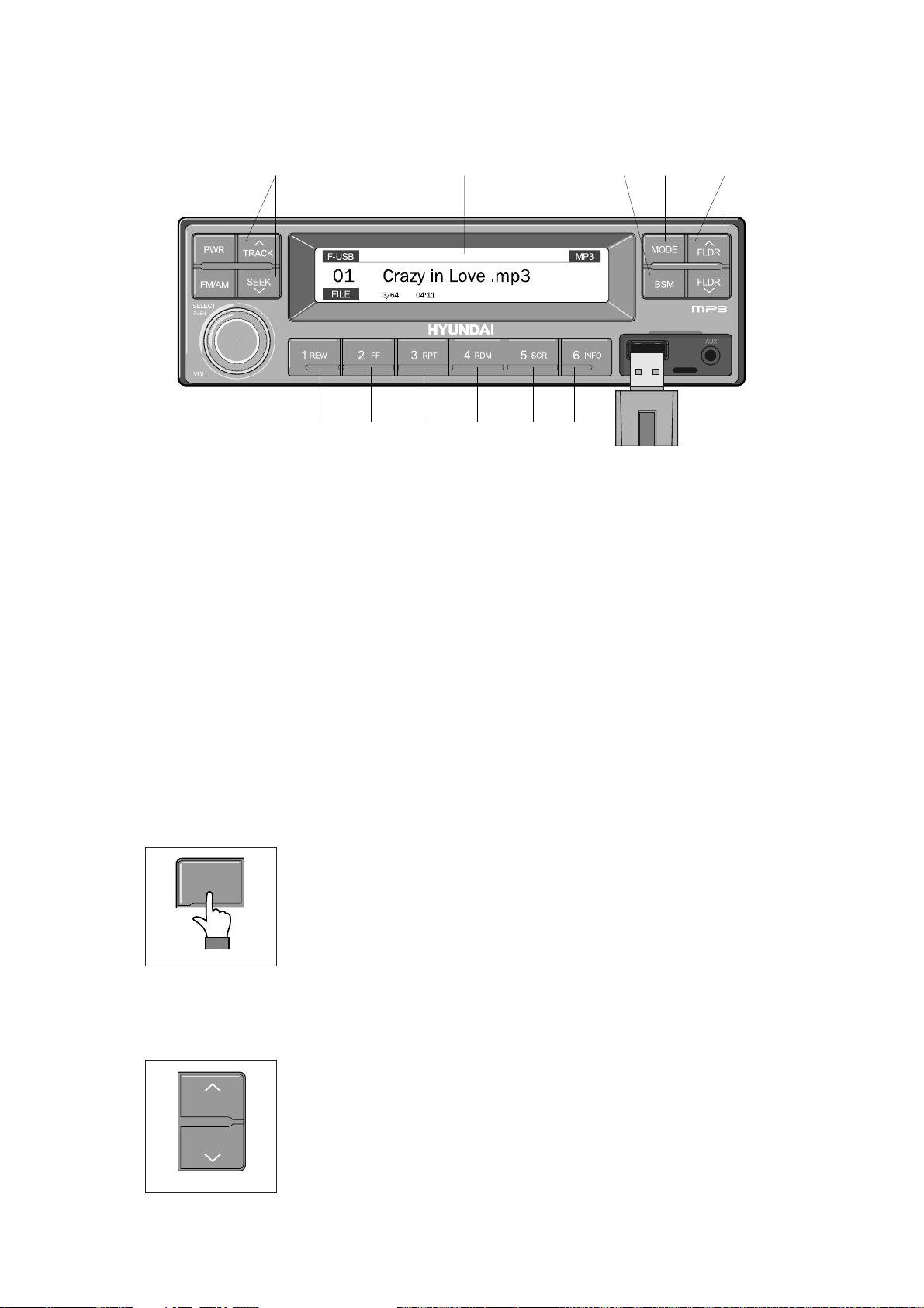
ÿ
USB
CONNECTION
USB selection button
(1)
TRACK UP/SEEK
DOWN
button
(2)
USB
CONNECTION
https://truckmanualshub.com/
2 11 19 3
10 4 4 5 6 7 8
2209S3CD72
1 USB selection button
2 TRACK UP/SEEK DOWN button
3 FLDR UP/DOWN button
4 FF/REW button
5 RPT/FOLDER RPT button
7 Scroll (SCR) button
8 View music info (INFO) button
9 Scan button (BSM)
10 Finding and playing file (SELECT) button
11 LCD display
6 RDM/FOLDER RDM button
Â
Operates only when a USB is connected. Connecting a USB to the audio will automatically convert
to USB mode.
Â
Connecting the USB when the starting switch is in ON state will turn the power on and automatically
play the songs within the USB.
USB selection button
(1)
Η
While playing a different mode, press the MODE button to convert
MODE
to USB mode. Connecting a USB to the audio will automatically
convert to USB mode even if another mode is playing and
automatically play the songs within the USB.
2209S3CD70D
Θ
If the USB is connected to both the front USB and handfree, then
MODE is converted in the following order.
RADIO
Ą
USB(front) Ą USB(handfree)
TRACK UP/SEEK
(2)
TRACK
SEEK
2209S3CD71B
DOWN
button
Η
While playing USB, press the TRACKĚ button to play the beginning
of the next song.
Press the SEEK
ě
button to return to the beginning of the current
song. Press the button again to play the beginning of the previous
song.
3-44
Page 94

FLDR UP/DOWN button
(3)
FF/REW button
RPT/FOLDER RPT button
Scroll (SCR) button
RDM/FOLDER RDM
button
(4)
(5)
(7)
(6)
FLDR UP/DOWN button
(3)
FLDR
FLDR
2209S3CD71C
FF/REW button
(4)
2209S3CD72A
https://truckmanualshub.com/
Η
If there are more than 2 folders in the USB, pressing the FLDR UP/
DOWN button will move to the previous or next folder.
Θ
If there are no folders in the USB, then pressing the button will move
up/down within the folder in 10 file increments.
Η
While a USB is operating, press and hold the FF button to fast-
forward the song. When fast-forward is complete, the next song will
properly play from the beginning even if you continue holding the
button. Press and hold the REW button to rewind the song. When
rewind is complete, the current song will properly play from the
beginning even if you continue holding the button. Shortly pressing
the buttons will not operate the FF/REW.
RPT/FOLDER RPT button
(5)
2209S3CD72B
RDM/FOLDER RDM
(6)
2209S3CD72C
Scroll (SCR) button
(7)
Η
Θ
button
Η
Θ
Η
While music is playing, shortly press the RPT button to repeat the
currently playing song.
(RPT function) Press and hold the RTP button to sequentially
repeat all songs within the current folder. (FOLDER RPT, however,
music files in the USB must be saved in folder format.)
While music is playing, shortly press the RDM button to randomly
play the songs in the current folder. (RDM)
While music is playing, press and hold the RDM button to randomly
play the songs in the current folder. (FOLDER RDM, however,
music files in the USB must be saved in folder format.)
Press the SCR button to turn ON/OFF the scroll function which
scrolls the file name of the currently playing song on the LCD from
right to left.
2209S3CD72D
3-45
Page 95

Scan button
(BSM)
(9)
Finding and playing file (SELECT) button
LCD display
(10)
(11)
View music info
(INFO)
button
(8)
https://truckmanualshub.com/
iew music info
(8)
(INFO)
button
Η
Each time the INFO button is pressed, the info on the currently
playing song will be displayed in the following order.
FILE NAME
2209S3CD72E
can button
(9)
(BSM)
Η
While music is playing, shortly press the BSM button to scan each
song within the USB for 10 seconds in sequential order. (SCN)
Θ
Press and hold the BSM button to scan each song within the
current folder for 10 seconds in sequential order. (FOLDER SCN,
2209S3CD71E
Finding and playing file (SELECT) button
(10)
SELECT
PUSH
however, music files in the USB must be saved in folder format.)
Η
While USB is playing, press and hold the SELECT button for over 3
seconds to enter FILE BROWER mode and search for desired files.
Ą
TITLE Ą ARTIST Ą ALBUM Ą DIR
VOL
LCD display
(11)
2209S3CD70C
2209S3CD71F
Θ
After entering FILE BROWSER mode, turn the SELECT button left/
right to find the desired folder. After finding the folder, press the
SELECT button to select the folder. Turn the SELECT button left/
right to find the desired song and press the SELECT button to play.
Ι
If there are no adjustments for 3 seconds after pressing the
SELECT button, the function will be turned off and the USB play
screen will be displayed.
Η
Displays the info of the currently playing song.
Â
F-USB : Displays USB is connected to the Audio Front
Â
R-USB : Displays USB is connected to the handfree
Â
RPT : Displays that repeat function is turned on
Â
RPT : Displays that folder repeat function is turned on
Â
RDM : Displays that random play is turned on
Â
RDM : Displays that folder random play is turned on
Â
SCR : Displays that SCROLL is turned on
3-46
Page 96

ÿ
iPOD CONNECTION
iPod selection button
(1)
TRACK UP/SEEK DOWN button
(2)
POD CONNECTION
8 3 3 4 5 6 7
https://truckmanualshub.com/
2 1
2209S3CD73
1 iPod selection button
2 TRACK UP/SEEK DOWN button
3 FF/REW button
4 Repeat (RPT) button
Â
Operates only when an iPod is connected. Connecting an iPod to the audio will automatically convert
5 Random play (RDM) button
6 Scroll (SCR) button
7 View music info (INFO) button
8 Finding and playing file (SELECT) button
to iPod mode. Connecting the USB when the starting switch is in ON state will turn the power on and
automatically play the songs within the iPod.
Â
The iPod cable is supplied separately.
iPod selection button
(1)
Η
While playing a different mode, press the MODE button to convert
MODE
to iPod mode. Connecting an iPod to the audio will automatically
convert to iPod mode even if another mode is playing and
automatically play the songs within the iPod.
2209S3CD70D
TRACK UP/SEEK DOWN button
(2)
Η
FLDR
FLDR
2209S3CD71C
While playing music, press the TRACKĚ button to play the
beginning of the next song.
Press the SEEK
ě
button to return to the beginning of the current
song. Press the button again to play the beginning of the previous
song.
3-47
Page 97

Repeat (RPT) button
Random play (RDM) button
View music info (INFO) button
Scroll
(SCR)
button
FF/REW
button
(4)
(5)
(7)
(6)
(3)
FF/REW
(3)
Repeat (RPT) button
(4)
button
2209S3CD72A
https://truckmanualshub.com/
Η
While an iPod is operating, press and hold the FF button to fast-
forward the song.
Θ
When fast-forward is complete, the next song will properly play from
the beginning even if you continue holding the button. Press and
hold the REW button to rewind the song.
Ι
When rewind is complete, the current song will properly play from
the beginning even if you continue holding the button.
Κ
Shortly pressing the buttons will not operate the FF/REW.
Η
While music is playing, press the RPT button to repeat the currently
playing song.
2209S3CD72B
Random play (RDM) button
(5)
2209S3CD72C
croll
(6)
(7)
(SCR)
View music info (INFO) button
button
2209S3CD72D
Η
While music is playing, press the RDM button to randomly play the
songs.
Η
Displays the file name of the currently playing song on the LCD.
Here, the SCR button turns the file name SCROLL ON/OFF.
Η
Each time the INFO button is pressed, the info on the currently
playing song will be displayed in order of ARTIST
Ą
ALBUM Ą
TITLE.
2209S3CD72E
3-48
Page 98

Finding and playing file (SELECT) button
(8)
https://truckmanualshub.com/
Finding and playing file (SELECT) button
(8)
SELECT
PUSH
Η
While iPod is playing, press and hold the SELECT button for over 3
seconds to enter CATEGORY mode and search for desired files.
Θ
VOL
2209S3CD70C
After entering CATEGORY mode, turn the SELECT button left/right
to find the desired category.
Ι
Category will be displayed in the following order.
PLAYLISTS
COMPOSERS Ą AUDIOBOOKS Ą PODCACSTS
Κ
After finding the category, press the SELECT button to select the
category. Turn the SELECT button left/right to find the desired song
and press the SELECT button to play.
Λ
If there are no adjustments for 3 seconds after pressing the
SELECT button, the function will be turned off and the iPod play
screen will be displayed.
Ą
ARTISTS Ą ALBUMS Ą GENRES Ą SONGS Ą
3-49
Page 99

ÿ
AUX connection
Connecting an external device using the AUX cable
(1)
AUX connection
https://truckmanualshub.com/
2209S3CD74
Â
Operates only when an external device is connected to AUX. Connecting an AUX device to the
audio using the AUX cable will automatically convert to AUX mode.
Â
When an external device is connected, only the PWR, FM/AM, MODE, and VOL buttons can be
operated.
Â
Settings can be made only through the external device connected to AUX.
Â
The AUX cable is supplied separately.
Connecting an external device using the AUX cable
(1)
Η
While playing a different mode, press the MODE button to convert to AUX mode.
Θ
If an external device is connected to the Audio through the AUX terminal, AUX mode will
automatically be converted and play music from AUX. Connecting the AUX when the starting
switch is in ON state will turn the power on and automatically play the songs within the AUX.
3-50
Page 100

This switch adjust the audio volume when selected audio mode.
Power and volume switch
(1)
Mode change button
(2)
REMOTE CONTROLLER
3)
This can be used when the starting switch is ON.
Call button
(3)
REMOTE CONTROLLER
3)
Handsfree jack MIC
Mode button
https://truckmanualshub.com/
VOL
MIC
SEEK
MODE
/.
MUTE
Power/Volume switch
Seek button
Mute button
Call button
Power and volume switch
(1)
VOL
.
MIC
MODE
Mode change button
(2)
MODE
/
SEEK
MUTE
21093CD52A
SEEK
MUTE
CALL
This switch is used to turn the audio or handsfree ON or OFF.
①
This switch is turned to right, the handsfree volume is increased over
②
Mode change button
7 steps.
If it is turned to left, volume will be decreased.
③
This switch adjust the audio volume when selected audio mode.
※
①
This button is to select the handsfree mode or audio mode.
·
Lamp ON : Handsfree mode ("TEL MUTE" displayed ON audio
LCD)
·
Lamp OFF : Audio mode
21093CD52
CALL
Call button
(3)
MODE
CALL
SEEK
21093CD52B
MUTE
21093CD52C
①
This button is used answer a call, last number redial, ring off.
②
For calling, press the button over 0.5
sec
within 3 seconds until the
beep sounds.
※
This can be used when the starting switch is ON.
3-51
 Loading...