


HUV4421G
Table of contents
 Loading...
2007
Utility Vehicles
Gasoline and Diesel
Owner’s Manual
HUV 4421G
HUV 4421GXP
HUV 4421D
HUV 4421DXP


NOTICE
Warranty information appears on the last pages of this manual. No other warranties, express or implied, are
contained herein. Your authorized representative checked the vehicle before it was delivered to you and will
provide you a copy of the completed vehicle warranty registration form.
Husqvarna is not liable for errors in this manual or for incidental or consequential damages that result from the
use of the material in this manual.
This manual contains proprietary information that is protected by copyright. All rights are reserved. No part of
this manual may be photocopied, reproduced, or translated to another language without the written consent
of Husqvarna, Inc.
The information contained in this document is subject to change without notice.
Husqvarna reserves the right to make design changes to vehicles without obligation to make these changes
on units previously sold.
These vehicles do not conform to Federal Motor Vehicle Safety Standards for automobiles or to FMVSS 500
for low-speed vehicles, and are not equipped for operation on public streets, roads, or highways.
Husqvarna Forest and Garden
7349 Statesville Rd.
Charlotte, NC 28269
USA
www.usa.husqvarna.com/huv
2007 HUV 4421 Gasoline and Diesel Vehicle Owner’s Manual Page 1

FOREWORD
Thank you for choosing Husqvarna, a world leader in outdoor products. You have chosen the finest utility
vehicle on the market. Please protect your investment and ensure that your Husqvarna vehicle provides years
of reliable, superior performance by reading and following the maintenance instructions in this manual.
Your comfort and safety are important to us, so we urge you to read and follow the step-by-step operating
instructions and safety procedures in this manual. These instructions must be followed in order to avoid the
risk of severe personal injury. If you rent or loan your vehicle to others, we recommend that you ask them to
read this manual before they operate the vehicle.
Husqvarna products are backed by a customer support system designed to offer you fast, courteous service.
In the event that your Husqvarna vehicle needs repairs or service, we recommend that your local authorized
Husqvarna representative perform them. For the name and address of the Husqvarna representative nearest
you, logon to our web site at www.usa.husqvarna.com. If you would prefer to write to us, direct your letter to:
Husqvarna, Attention: Marketing Services, 7349 Statesville Rd., Charlotte, NC 28269 USA. Your local authorized Husqvarna representative can also provide technical advice, parts, and service manuals.
We hope you will consider this owner’s manual a permanent part of your Husqvarna vehicle. If you sell the
vehicle, please include the manual so that the next owner will have the important operating, safety, and maintenance information it contains. Translated owner’s manuals can be downloaded from the Husqvarna web
site at www.usa.husqvarna.com/huv.
Page 2 2007 HUV 4421 Gasoline and Diesel Vehicle Owner’s Manual

TABLE OF CONTENTS
Safety Details ............................................................................................................................................ 7
General Warnings ...................................................................................................................................... 8
General Information ................................................................................................................................... 10
Model Identification .................................................................................................................................... 10
Controls and Indicators .............................................................................................................................. 10
Roll-Over Protective Structure and Safety Belts ........................................................................................ 15
Seat Latch and Adjustment ....................................................................................................................... 17
Pre-Operation and Daily Safety Checklist ................................................................................................. 17
Performance Inspection ............................................................................................................................. 18
Driving Instructions .................................................................................................................................... 19
Bed Latch and Prop Rod – HUV 4421G and HUV 4421D Only ................................................................ 22
Loading and Unloading Cargo ................................................................................................................... 23
Vehicle Load Capacities ............................................................................................................................ 23
Towing with the Vehicle ............................................................................................................................. 25
Transporting on a Trailer ........................................................................................................................... 25
Storage ...................................................................................................................................................... 26
Maintenance .............................................................................................................................................. 28
Periodic Service Schedule ......................................................................................................................... 29
Periodic Lubrication Schedule ................................................................................................................... 32
Brake Fluid Reservoir ................................................................................................................................ 33
Engine Oil .................................................................................................................................................. 34
Gearcase Lubrication ................................................................................................................................ 39
Engine Coolant – Diesel Vehicles ............................................................................................................. 41
Air Intake System ...................................................................................................................................... 41
Fueling Instructions ................................................................................................................................... 42
Battery ....................................................................................................................................................... 45
Using A Booster Battery (Jump Starting) ................................................................................................... 46
Cleaning the Vehicle .................................................................................................................................. 47
Accessories ............................................................................................................................................... 48
Subsequent Owner Registration ................................................................................................................ 49
Vehicle Specifications ................................................................................................................................ 50
2007 HUV 4421 Gasoline and Diesel Vehicle Owner’s Manual Page 3
ALL HUV 4421 MODELS
DIESEL WARNING DECAL
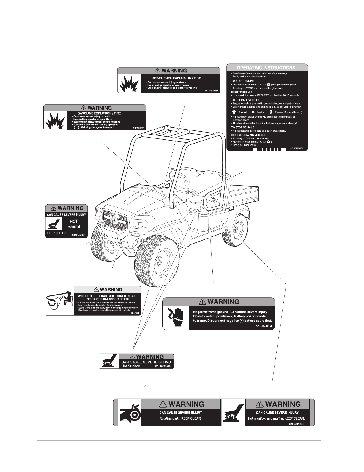
Vehicle Feature Identification
GASOLINE WARNING DECAL
(GASOLINE VEHICLES ONLY,
ON PASSENGER-SIDE SEAT SUPPORT)
HOT MANIFOLD
WARNING DECAL
(ON ENGINE
VALVE COVER)
(DIESEL VEHICLES ONLY,
ON PASSENGER-SIDE SEAT SUPPORT)
OPERATING
INSTRUCTIONS
(ON INSTRUMENT PANEL)
WINCH CABLE WARNING DECAL
(FOR VEHICLES WITH WINCH ACCESSORY)
(ON FRONT BODY)
HOT SURFACE WARNING DECAL
(ON COOLANT PIPES AND
UNDERSIDE OF BOTH SEATS)
FRAME GROUND WARNING DECAL
(ON VEHICLE FRAME NEAR BATTERY)
ROTATING PARTS AND HOT MANIFOLD DECAL
(ON DRIVER-SIDE VEHICLE FRAME)
Page 4 2007 HUV 4421 Gasoline and Diesel Vehicle Owner’s Manual
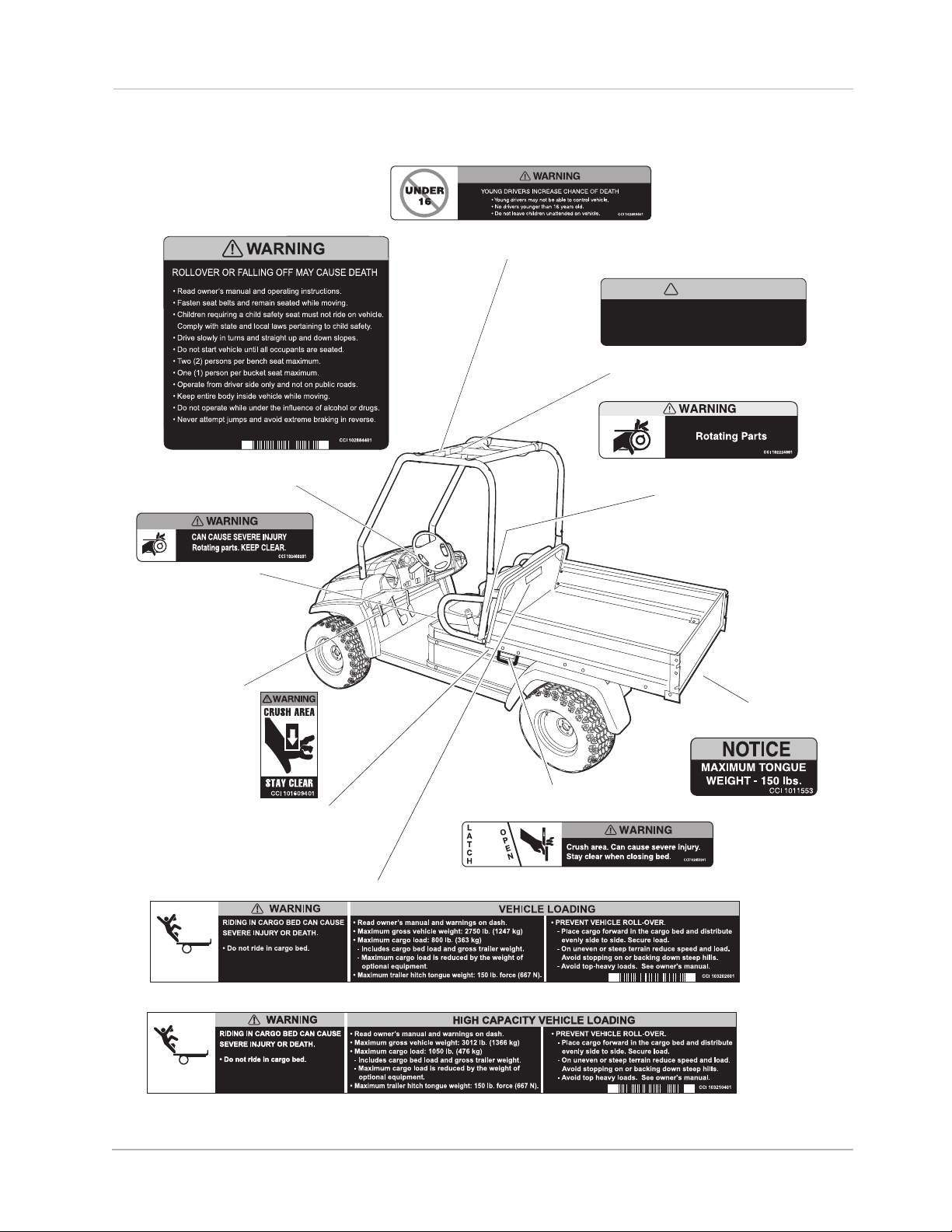
ALL HUV 4421 MODELS
UNDERAGE
WARNING DECAL
• Do not modify or remove Roll-over Protective Structure (ROPS).
• Replace ROPS if damaged. Do not attempt repair.
• Use seat belts during operation. Do not jump from vehicle.
• Keep away from drop-offs, steep slopes, and unstable
surfaces.
NOTICE AND WARNING DECAL
Vehicle Feature Identification
!
WARNING
CCI 102961201
CERTIFICATION
DRIVER/PASSENGER WARNING
DECAL
ROTATING PARTS
DECAL - DIESEL
(UNDER SEAT ON
DRIVER-SIDE FRAME)
SERIAL NUMBER
DECAL
CRUSH AREA DECAL
AND PASSENGER SIDE)
VEHICLE LOADING DECAL
(ON DRIVER SIDE
(UNDER SEAT ON DRIVER-SIDE FRAME)
BED LATCH
WARNING DECAL
ROTATING PARTS DECAL - GAS
TRAILER HITCH
DECAL
(ON REAR RECEIVER HITCH)
(STANDARD VEHICLE)
(HIGH-CAPACITY OPTION)
2007 HUV 4421 Gasoline and Diesel Vehicle Owner’s Manual Page 5

Vehicle Feature Identification
Page 6 2007 HUV 4421 Gasoline and Diesel Vehicle Owner’s Manual
Safety Details
SAFETY DETAILS
ý WARNING
• This owner’s manual should be read completely before attempting to drive or service the
vehicle. Failure to follow the instructions in this manual could result in property damage,
severe personal injury, or death.
It is important to note that some vital statements throughout this manual and on the decals affixed to the vehicle are preceded by the words DANGER, WARNING, or CAUTION. For your protection, we recommend that
you take special notice of these safety precautions. Safety precautions are essential and must be followed.
If any of the operation or warning decals on the vehicle become damaged, have been removed, or cannot be
easily read, they should be replaced immediately to avoid possible property damage, personal injury, or
death. Contact your Husqvarna dealer.
ý DANGER
• A DANGER indicates an immediate hazard that will result in severe personal injury or death.
ý WARNING
• A WARNING indicates an immediate hazard that could result in severe personal injury or
death.
ý CAUTION
• A CAUTION with the safety alert symbol indicates a hazard or unsafe practice that could
result in minor personal injury.
CAUTION
• A CAUTION without the safety alert symbol indicates a potentially hazardous situation that
could result in property damage.
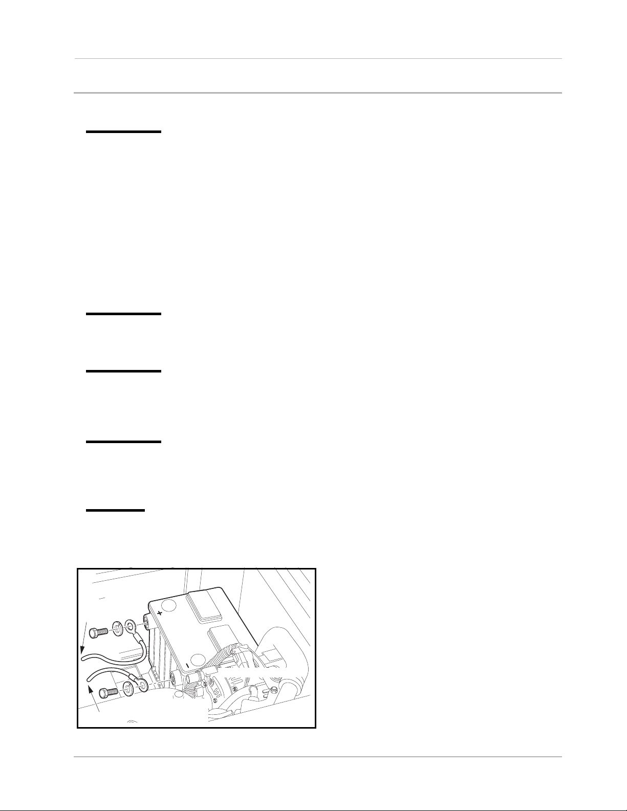
POS
TO FUSE BLOCK
NEG
TO GROUND
DIESEL VEHICLE SHOWN
Remove negative (–)
cable first.
Figure 1 Battery Cable Removal
2007 HUV 4421 Gasoline and Diesel Vehicle Owner’s Manual Page 7

General Warnings
GENERAL WARNINGS
The following safety statements must be heeded whenever the vehicle is being operated, repaired, or serviced. Safety decal identification information is also included beginning on page 4. Other specific safety statements appear throughout this manual and on the vehicle.
ý
DANGER
• Battery – Explosive gases! Do not smoke. Keep sparks and flames away from the vehicle and
service area. Ventilate when charging or operating vehicle in an enclosed area. Wear a full
face shield and rubber gloves when working on or near batteries.
• Gasoline/Diesel – Flammable! Explosive! Do not smoke. Keep sparks and flames away from
the vehicle and service area. Service only in a well-ventilated area.
• Do not operate engine in an enclosed area without proper ventilation. The engine produces
carbon monoxide, which is an odorless, deadly poison.
• A Husqvarna vehicle will not provide protection from lightning, flying objects, or other stormrelated hazards. If caught in a storm while driving a Husqvarna vehicle, exit the vehicle and
seek shelter in accordance with applicable safety guidelines for your location.
ý WARNING
• Follow the procedures exactly as stated in this manual, and heed all DANGER, WARNING, and
CAUTION statements in this manual as well as those on the vehicle.
• Do not leave children unattended on vehicle.
• Children requiring a child safety seat must not ride on the vehicle. Comply with state and local
laws pertaining to child safety.
• The driver and passenger must be restrained at all times with the safety belts provided to help
prevent injury in the event of sudden braking, collision, or roll-over.
• No more than one person per bucket seat at one time. No more than two persons per bench
seat at one time. Do not allow people to ride in any part of the vehicle that is not equipped with
a seat and a safety belt. Do not allow a passenger to hold a child in his or her lap while the
vehicle is moving.
• Prior to leaving the vehicle unattended or servicing the vehicle, place attachment on the
ground, set the park brake, place the Forward/Reverse handle in the NEUTRAL position, turn
the key switch to the OFF position, and remove the key. Chock the wheels when servicing the
vehicle.
• Improper use of the vehicle or failure to properly maintain it could result in decreased vehicle
performance, severe personal injury, or death.
• Any modification or change to the vehicle that affects the stability or handling of the vehicle,
or increases maximum vehicle speed beyond factory specifications, could result in severe
personal injury or death.
• Check the vehicle for proper location of all vehicle safety and operation decals and make sure
they are in place and are easy to read.
• For vehicles with cargo beds, remove all cargo before raising the bed or servicing the vehicle.
If the vehicle is equipped with a prop rod, ensure that it is securely engaged while bed is
raised. Do not close bed until all persons are clear of cargo bed area. Keep hands clear of all
crush areas. Do not drop cargo bed; lower gently and keep entire body clear. Failure to heed
this warning could result in severe personal injury or death.
WARNING CONTINUED ON NEXT PAGE...
Page 8 2007 HUV 4421 Gasoline and Diesel Vehicle Owner’s Manual
General Warnings
ý WARNING
• Only trained technicians should service or repair the vehicle. Anyone doing even simple
repairs or service should have knowledge and experience in electrical and mechanical repair.
The appropriate instructions must be used when performing maintenance, service, or
accessory installation.
• To avoid unintentionally starting the vehicle:
- Disconnect battery cables, negative (–) cable first (Figure 1).
- Gasoline vehicles only: Disconnect the spark plug wires from the spark plugs.
• Frame ground – Do not allow tools or other metal objects to contact frame when
disconnecting battery cables or other electrical wiring. Do not allow a positive wire to touch
the vehicle frame, engine, or any other metal component.
• Wear safety glasses or approved eye protection when servicing the vehicle. Wear a full face
shield and rubber gloves when working on or near batteries.
• Do not wear loose clothing or jewelry such as rings, watches, chains, etc., when servicing the
vehicle.
• Use insulated tools when working near batteries or electrical connections. Use extreme
caution to avoid shorting of components or wiring.
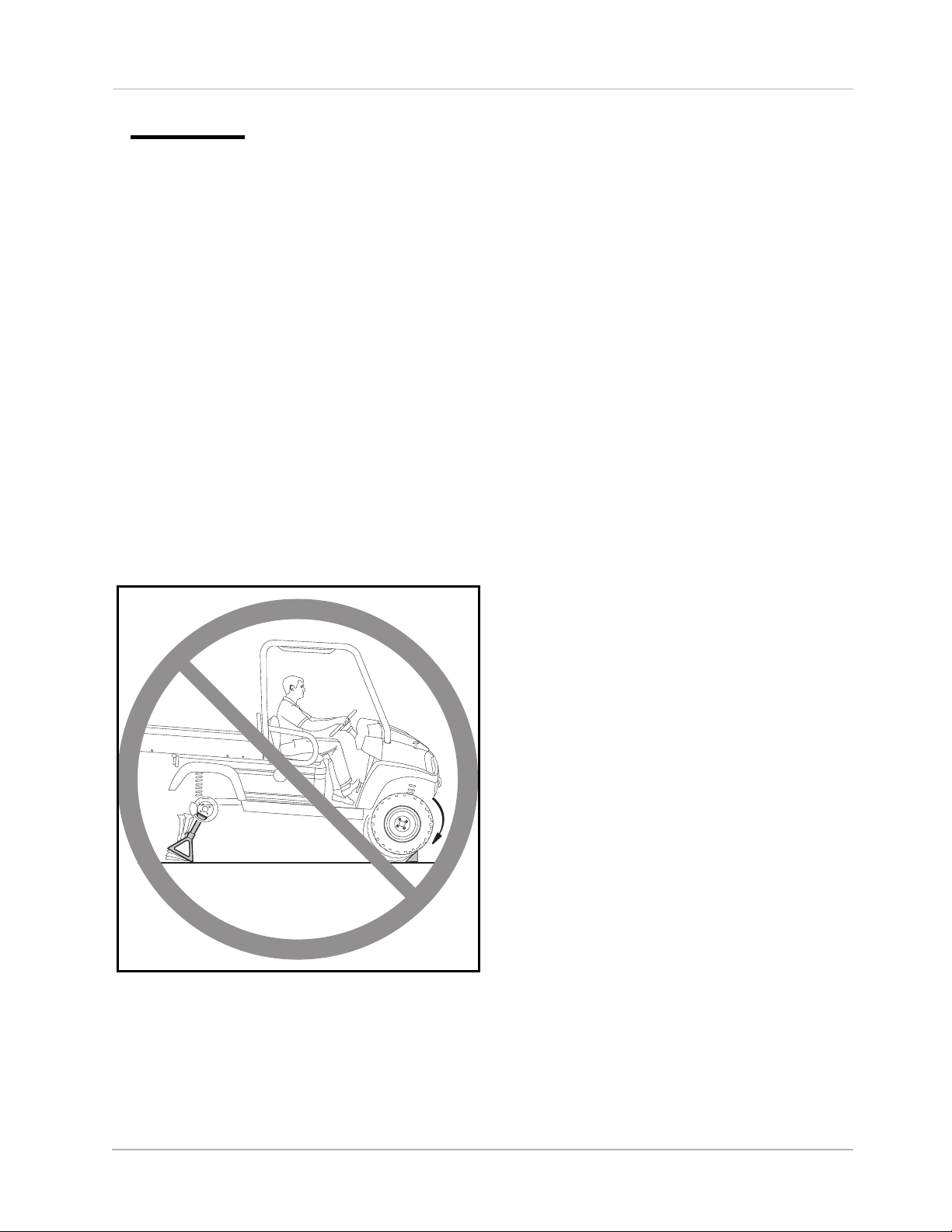
• When servicing the vehicle with part of the vehicle on jack stands, do not operate the engine
with the Forward/Reverse handle in either the FORWARD or REVERSE position. The all-wheel
drive system will engage any wheel(s), front or rear, with traction.
Figure 2 All-wheel Drive Warning
2007 HUV 4421 Gasoline and Diesel Vehicle Owner’s Manual Page 9
General Information
SERIAL NUMBER
DH0601-123456
GENERAL INFORMATION
This manual includes operating procedures, maintenance, and regular servicing information for HUV 4421G,
HUV 4421D, HUV 4421GXP, and HUV 4421DXP gasoline and diesel vehicles. All operating procedures,
maintenance, and regular servicing are identical unless otherwise noted.
MODEL IDENTIFICATION
The serial number of each vehicle is printed on a bar code decal mounted on the frame above the brake pedal
(Example: RC0601-123456) (Figure 3). There is also a second serial number decal mounted on the rear
body frame behind the fuel tank. The fuel tank must be removed to view this decal. See following NOTE.
NOTE: Have the vehicle serial number available when ordering parts or making inquiries.
7349 STATESVILLE RD.
CHARLOTTE, NC 28269
Figure 3 Serial Number
CONTROLS AND INDICATORS
See General Warnings on page 8.
ý WARNING
• Before allowing anyone to drive the vehicle, make sure the driver is familiar with all controls
and operating procedures.
• Do not tamper with the high idle speed setting on the diesel vehicle. Doing so will void the
warranty, as well as damage the engine and other components, and could result in property
damage, personal injury, or death due to unsafe speeds.
• Do not shift the Forward/Reverse handle while the vehicle is in motion.
• Engine must be at idle before shifting the Forward/Reverse handle. Failure to do so may result
in injury to inattentive passengers and (or) damage to the vehicle.
• To avoid unintentionally starting or rolling the vehicle, place attachment on the ground, set
the park brake, place the Forward/Reverse handle in the NEUTRAL position, turn the key
switch to the OFF position, and remove the key when leaving the vehicle.
Page 10 2007 HUV 4421 Gasoline and Diesel Vehicle Owner’s Manual
Controls and Indicators
9
8
A
01/21
1
10
OPERATING INSTRUCTIONS
12
OFF
ON
START
14
15
13
4
5
3
7
6
B
C
11
1
2
12
10
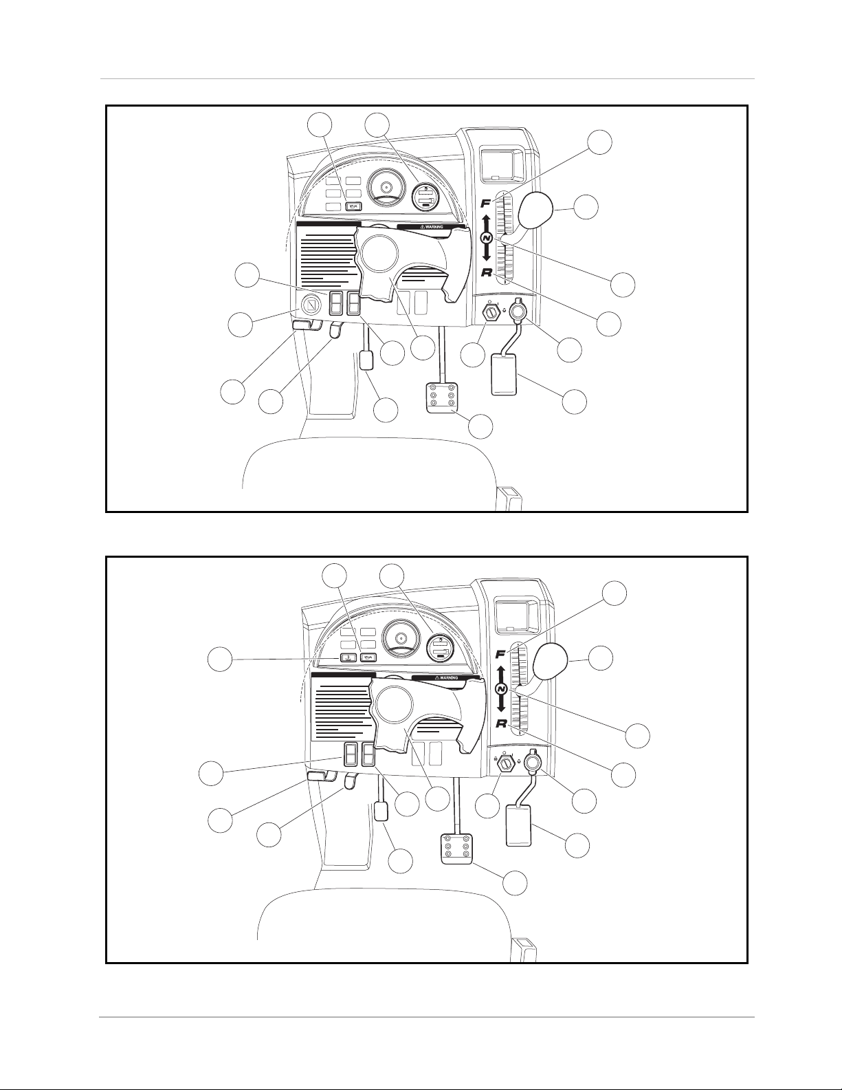
Figure 4 Instrument Panel – Gasoline Vehicles
9
8
A
01/21
1
10
OPERATING INSTRUCTIONS
6
B
OFF
PREHEAT
ON
START
C
13
15
7
11
4
5
1
3
2
Figure 5 Instrument Panel – Diesel Vehicles
2007 HUV 4421 Gasoline and Diesel Vehicle Owner’s Manual Page 11

Controls and Indicators
KEY SWITCH – GASOLINE VEHICLES
The key switch (7) is mounted on the instrument panel to the right of the steering column (Figure 4, Page 11).
It has three positions: OFF, ON, and START.
To start the vehicle, place the Forward/Reverse handle in the NEUTRAL position and turn the key to the
START position, and hold it there until the engine starts. Activate the choke (14) as necessary. If the engine
does not start after 10-15 seconds, release the key and repeat the procedure. Once the engine starts, release
the key and it will return to the ON position. The engine will idle in neutral.The engine will continue to idle until
the key is turned to the OFF position. See following WARNING, CAUTION, and NOTE.
ý WARNING
• Moving parts! Keep clear of the engine compartment while the engine is running.
CAUTION
• Do not shift the Forward/Reverse handle while the accelerator pedal is pressed. Shift the
handle only when the vehicle is at a complete stop and the engine is at idle. Failure to heed
this caution could result in damage to the transmission.
NOTE: The key can be removed only when the key switch is in the OFF position.
KEY SWITCH – DIESEL VEHICLES
The key switch (7) is mounted on the instrument panel to the right of the steering column (Figure 5, Page 11).
It has four positions: PREHEAT, OFF, ON, and START.
Use the PREHEAT feature if the temperature falls below 23 °F (–5 °C). Do not hold the key in the PREHEAT
position longer than 20 seconds. To preheat the glow plugs in cold weather, turn the key to the PREHEAT
position, and hold it there for 10-15 seconds. Then turn the key to the START position, and hold it there until
the engine starts. If the engine does not start after 10-15 seconds, turn the key to the OFF position and repeat
the procedure. Once the engine starts, release the key and it will return to the ON position. The engine will idle
in neutral. The engine will continue to idle until the key is turned to the OFF position. See previous WARN-
ING, CAUTION, and NOTE.
FORWARD/REVERSE CONTROL
The Forward/Reverse handle (6) is located on the right side of the instrument panel (Figure 4 and Figure 5,
Page 11). The handle has three distinct positions: FORWARD (A), NEUTRAL (B), and REVERSE (C). Push
the handle up to operate the vehicle in the forward direction, or pull the handle down to operate the vehicle in
reverse. The engine can be started only when the handle is in the NEUTRAL (middle) position. The engine
must be at idle before shifting the Forward/Reverse handle. See WARNING and CAUTION on page 12.
Husqvarna vehicles operate at a reduced speed in reverse. The reverse buzzer will sound as a warning when
the Forward/Reverse handle is in the REVERSE position.
ACCELERATOR PEDAL
The accelerator pedal (1) is the pedal farthest to the right (Figure 4 and Figure 5, Page 11).
With the engine running and the Forward/Reverse handle in the FORWARD or REVERSE position, vehicle
speed will increase as the accelerator pedal is pressed. When the accelerator pedal is released, it will return
to the original position and the engine will idle. See WARNING and CAUTION on page 12.
Page 12 2007 HUV 4421 Gasoline and Diesel Vehicle Owner’s Manual
Controls and Indicators
BRAKE PEDAL
The brake pedal (2) is located to the immediate left of the accelerator pedal (Figure 4 and Figure 5, Page
11). To slow or stop the vehicle, press the brake pedal.
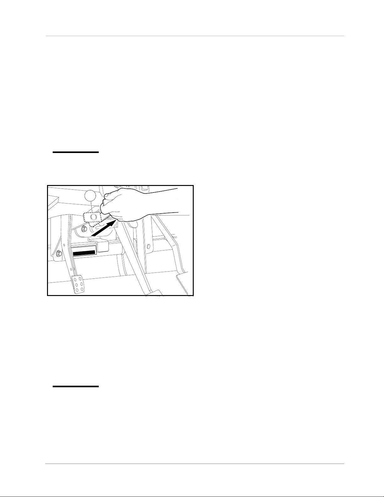
PARK BRAKE
The park brake pedal (3) is located to the left of the brake pedal (Figure 4 and Figure 5, Page 11). To engage
the park brake, first apply pressure to the brake pedal, then firmly press the park brake pedal until it latches
into place. To disengage the park brake, pull the park brake release handle (4) (Figure 6). See following
WARNING.
ý WARNING
• The park brake has multiple locking positions and should be firmly locked to prevent the
vehicle from rolling.
4
P
P
R
E
B
M
U
N
L
IA
R
E
S
TR0601-123456
Figure 6 Park Brake Release
STEERING ADJUSTMENT LOCK
The steering wheel position is adjustable. To adjust the steering wheel position, press down on the steering
adjustment lock lever (5), then move the steering wheel to the desired position
(Figure 4 and Figure 5,
Page 11). While holding the steering wheel in the desired position, pull up on the steering adjustment lock
lever to firmly lock the steering column in position. See following WARNING.
ý WARNING
• Ensure that the steering wheel lock is fully engaged before operating the vehicle.
12-VOLT ACCESSORY OUTLET
The 12-volt accessory outlet (11) is located to the right of the key switch (Figure 4 and Figure 5, Page 11). It
provides a constant 12VDC with the key switch in the ON or OFF position. See following NOTE.
NOTE: Extended use of this accessory outlet can cause the battery to become heavily discharged.
2007 HUV 4421 Gasoline and Diesel Vehicle Owner’s Manual Page 13

Controls and Indicators
LOW OIL WARNING LAMP
The low oil warning lamp (9) is located on the instrument panel just to the left of the steering column (Figure 4
and Figure 5, Page 11). If the warning lamp lights up, oil should be checked and added to the engine as nec-
essary before vehicle use continues. The vehicle should never be driven when the low oil warning lamp
remains lit. If the warning lamp alternately lights and darkens, the vehicle may be driven, but oil should be
added at the first opportunity. If the oil level is correct and the warning lamp remains lit, have a trained technician check the vehicle. See following CAUTION.
CAUTION
• Failure to add oil immediately when the low oil warning lamp remains lit may result in
permanent engine damage.
FUEL GAUGE/HOUR METER
The fuel gauge and hour meter (8) are housed together on the right side of the instrument panel (Figure 4
and Figure 5, Page 11). The fuel gauge operates when the key switch is in the ON position and allows the
operator to monitor the fuel level in the vehicle. The hour meter operates only when the engine is running, and
should be used by the trained technician to track vehicle usage and determine when periodic service procedures are required. See Periodic Service Schedule on page 29.
HEADLAMP CONTROL
The headlamp control (12) is located on the left side of the instrument panel (Figure 4 and Figure 5, Page
11). Press the headlamp rocker switch to turn the headlamps on or off. See following NOTE.
NOTE: Using the headlamps for extended periods while the engine is either off or idling will discharge the
battery.
ELECTRIC BED LIFT – OPTIONAL ON SOME VEHICLES
The electric bed lift switch (13) is located on the instrument panel to the left of the key switch (Figure 4 and
Figure 5, Page 11). See following NOTE.
NOTE: Remove cargo before raising the bed.
To lift the bed, push up and hold the rocker switch in the upper position. Release the switch to stop the lifting
operation. To close the bed, press down and hold the switch in the lower position. The bed lift will make a loud
clicking sound to signal that the bed is in the rest position.
HIGH-TEMPERATURE WARNING LAMP – DIESEL VEHICLES ONLY
The high-temperature warning lamp (10) is located on the instrument panel to the left of the steering column,
next to the low oil warning lamp (9) (Figure 5, Page 11). The diesel engine is liquid-cooled; if the engine coolant has exceeded its normal safe operating temperature, the warning lamp will illuminate. If the warning lamp
lights up, stop the vehicle and allow it to idle for approximately five minutes before stopping the engine. Contact a Husqvarna dealer/distributor or a trained technician. See following WARNING.
ý WARNING
• Allow the engine to cool before servicing the engine coolant system. Engine coolant can
cause severe burns.
Page 14 2007 HUV 4421 Gasoline and Diesel Vehicle Owner’s Manual
Roll-Over Protective Structure and Safety Belts
ROLL-OVER PROTECTIVE STRUCTURE AND SAFETY BELTS
All HUV 4421 vehicles are equipped with a Roll-Over Protective Structure (ROPS) and safety belts for each
occupant. See following WARNING.
ý WARNING
• The ROPS must be properly installed before operating the vehicle. Husqvarna strongly urges
that the vehicle’s occupants be properly restrained at all times with the safety belts provided.
Pregnant woman: Consult your doctor for specific recommendations. The safety belt should be worn securely
and as low as possible over the hips and not on the waist.
Injured person: Depending on the injury, first check with your doctor for specific recommendations.
To secure the safety belt, sit up straight and well back in the seat. Pull the safety belt out of the retractor and
insert the tab into the buckle. A click will be heard when the tab locks into the buckle. Position the lap belt as
low as possible on the hips – not on the waist.
The retractor will lock the belt during a sudden stop. It also may lock if the occupant leans forward too quickly.
A slow, easy motion will allow the belt to extend, and the occupant can move freely. If the safety belt cannot
be pulled out of the retractor, firmly pull the belt and release it. It should then pull smoothly out of the retractor.
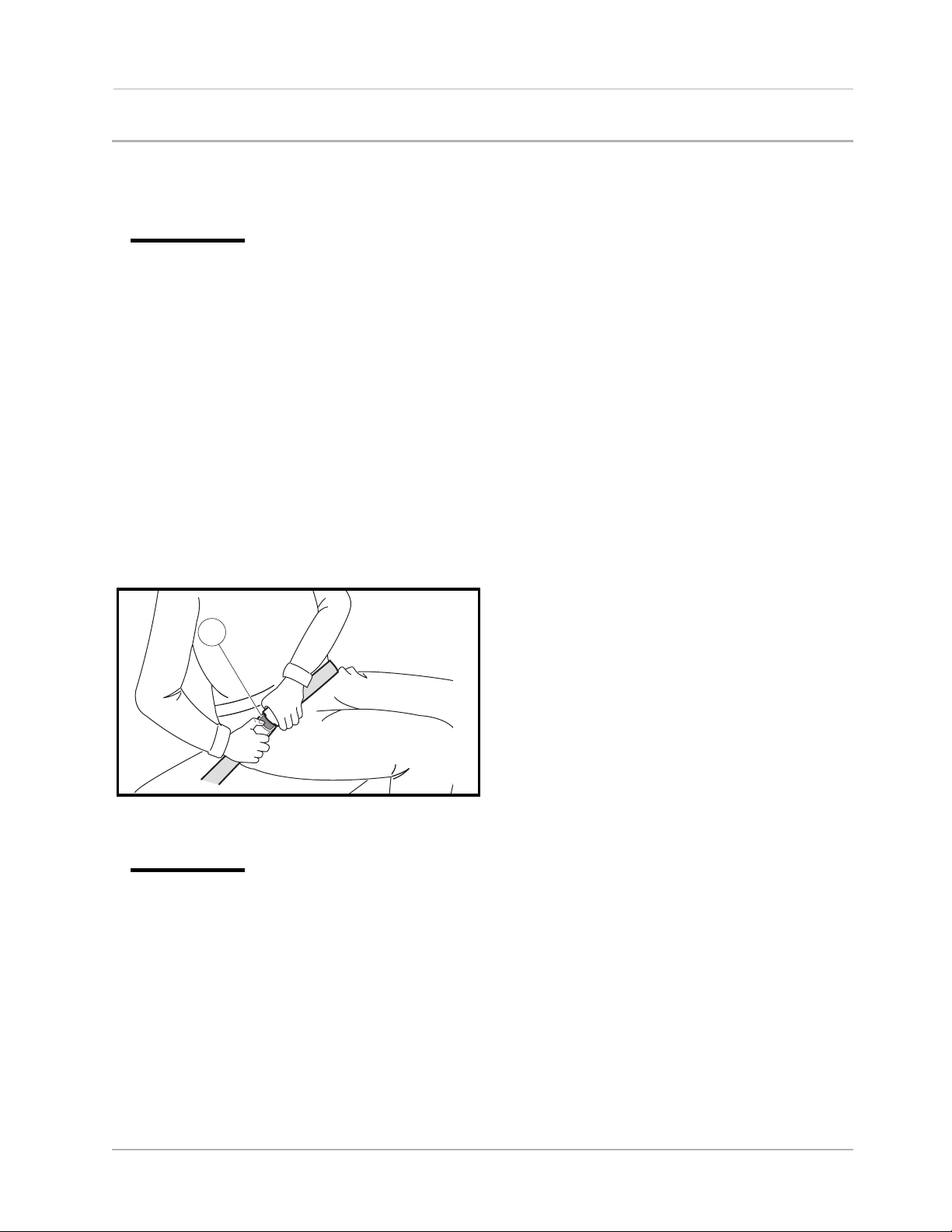
To release the safety belt, press the buckle release button (1) and allow the belt to retract (Figure 7). If the
belt does not retract smoothly, pull it out and check for kinks or twists. Then make sure it remains free of twists
as it retracts.
1
Figure 7 Release Safety Belt
ý WARNING
• Do not operate the vehicle with the ROPS removed. Doing so could result in property damage,
personal injury, or death.
• Do not remove or modify any component of the ROPS structure. Doing so will result in
voiding the ROPS certification and could weaken the ROPS, resulting in serious injury or
death.
• Do not operate the vehicle if the ROPS is damaged. If the ROPS is damaged, replace the
structure. Do not attempt repair.
• The driver and passenger must be restrained at all times with the safety belts provided to help
prevent injury in the event of sudden braking, collision, or roll-over.
• In the event of a roll-over, do not attempt to jump or otherwise exit the vehicle. Remain seated
with safety belt fastened and with arms and legs inside the vehicle.
WARNING CONTINUED ON NEXT PAGE...
2007 HUV 4421 Gasoline and Diesel Vehicle Owner’s Manual Page 15

Roll-Over Protective Structure and Safety Belts
ý WARNING
• After inserting the tab, make sure the tab and buckle are locked and that the belt is not
twisted.
• Loose fitting safety belts could increase the chance of injury due to sliding under the belt if
sudden braking should occur. Keep the safety belt snug and positioned as low on the hip
bone as possible.
• Use a single safety belt for one person at a time. Do not use a single safety belt for two or
more people – this includes children.
• No more than one person per bucket seat at one time. No more than two persons per bench
seat at one time. Do not allow people to ride in any part of the vehicle that is not equipped with
a seat and a safety belt. Do not allow a passenger to hold a child in his or her lap while the
vehicle is moving.
• The Husqvarna vehicle is not designed to meet child seat compatibility requirements.
Children requiring a child safety seat must not ride on the vehicle. Comply with state and local
laws pertaining to child safety.
ý CAUTION
• Be careful not to damage the safety belt webbing or hardware.
• Inspect the safety belt system periodically. Check for cuts, fraying, and loose parts. Damaged
parts should be replaced immediately. Do not disassemble or modify the system.
• Keep safety belts clean and dry. If cleaning is necessary, use a mild soap and lukewarm water
solution. Do not use bleach, dye or abrasive cleaners as they may severely weaken the safety
belts.
• Do not insert coins, clip, etc. in the buckle as this may prevent the tab from locking into the
buckle properly.
• If the safety belt does not function normally, contact your Husqvarna dealer/distributor or
trained technician immediately. Do not occupy the seat until the safety belt is repaired.
CARGO CAGE HEADRESTS
Vehicles Equipped with Cargo Cage Option
Some vehicles are equipped with a rear cargo cage. This cargo cage includes two adjustable headrests.
To adjust the headrests
1. Remove the headrest hardware (1) (Figure 8).
2. Raise or lower the headrest to the desired height.
3. Install the headrest hardware (1).
4. Hand-tighten the hardware until the headrest is securely attached to the cargo cage. See following
NOTE.
NOTE: Using tools to tighten the headrest hardware could result in overtightening. Overtightening the
headrest hardware could result in damage to the cargo cage structure and/or the hardware.
Page 16 2007 HUV 4421 Gasoline and Diesel Vehicle Owner’s Manual
Loading...