


 Loading...
2008 Utility Vehicles
Electric and Gasoline
Owner’s Manual
HUV4210-G
HUV4210-E
HUV4210-GXP
HUV4210-EXP

NOTICE
Warranty information appears on the last pages of this manual. No other warranties, express or implied, are contained herein. Please complete and return the warranty registration card included in this manual.
Husqvarna is not liable for errors in this manual or for incidental or consequential damages that result from the use of the material in this manual.
This manual contains proprietary information that is protected by copyright. All rights are reserved. No part of this manual may be photocopied, reproduced, or translated to another language without the written consent of Husqvarna.
The information contained in this document is subject to change without notice.
Husqvarna reserves the right to change specifications and designs at any time without notice and without the obligation of making changes to units previously sold.
These vehicles do not conform to Federal Motor Vehicle Safety Standards for automobiles or to FMVSS 500 for low-speed vehicles, and are not equipped for operation on public streets, roads, or highways.
Husqvarna Forest and Garden
7349 Statesville Rd.
Charlotte, NC 28269
USA www.usa.husqvarna.com/huv
2008 Husqvarna 4210-G, 4210-E, 4210-GXP, and 4210-EXP Owner’s Manual |
Page 1 |

FOREWORD
Thank you for choosing Husqvarna, a world leader in outdoor products. You have chosen the finest utility vehicle on the market. Please protect your investment and ensure that your Husqvarna vehicle provides years of reliable, superior performance by reading and following the maintenance instructions in this manual.
Your comfort and safety are important to us, so we urge you to read and follow the step-by-step operating instructions and safety precautions in this manual. These instructions must be followed in order to avoid the risk of severe personal injury. If you rent or loan your vehicle to others, we recommend that you ask them to read this manual before they operate the vehicle.
Husqvarna products are backed by a customer support system designed to offer you fast, courteous service. In the event that your Husqvarna vehicle needs repairs or service, we recommend that your local authorized Husqvarna representative perform them. For the name and address of the Husqvarna representative nearest you, logon to our web site at www.usa.husqvarna.com. If you would prefer to write to us, direct your letter to: Husqvarna, Attention: Marketing Services, 7349 Statesville Rd., Charlotte, NC 28269 USA. Your local authorized Husqvarna representative can also provide technical advice, parts, and service manuals.
We hope you will consider this owner’s manual a permanent part of your Husqvarna vehicle. If you sell the vehicle, please include the manual so that the next owner will have the important operating, safety, and maintenance information it contains. Translated owner’s manuals can be downloaded from the Husqvarna web site at www.usa.husqvarna.com.Below is a quick reference table of items that will help you maintain this vehicle. These parts can be purchased from your authorized Husqvarna dealer.
|
|
REGULAR MAINTENANCE ITEMS |
PERIODIC MAINTENANCE ITEMS |
|
|
Engine Oil Filter (286 cc and 351 cc) |
Battery (gasoline vehicle) |
(P/N 603 00 00-06) |
(P/N 603 00 00-02) |
|
|
Engine Air Filter (286 cc and 351 cc) |
Spark Plug O.H.V. (286 cc and 351 cc) |
(P/N 603 00 00-04) |
(P/N 603 00 00-07) |
|
|
Engine Fuel Filter (286 cc and 351 cc) |
Spring Tune-Up Kit |
(P/N 603 00 00-08) |
(P/N 603 00 00-05) |
|
|
Battery Terminal Protector Spray |
Battery (electric vehicle), 12 - Volt |
(P/N 603 00 00-03) |
(P/N 603 00 20-23) |
|
|
Dry Moly Lube |
|
(P/N 603 00 00-01) |
|
|
|
Page 2 2008 Husqvarna 4210-G, 4210-E, 4210-GXP, and 4210-EXP Owner’s Manual

TABLE OF CONTENTS |
|
Safety Decal and Feature Identification ..................................................................................................... |
4 |
Practice Safety .......................................................................................................................................... |
9 |
Proposition 65 – State of California ........................................................................................................... |
9 |
Safety Details ............................................................................................................................................ |
10 |
General Warnings ...................................................................................................................................... |
10 |
General Information ................................................................................................................................... |
12 |
Front Bumper and Brush Guard ................................................................................................................ |
12 |
Model Identification .................................................................................................................................... |
13 |
Controls and Indicators .............................................................................................................................. |
14 |
Pre-Operation and Daily Safety Checklist ................................................................................................. |
20 |
Performance Inspection ............................................................................................................................. |
21 |
Driving Instructions .................................................................................................................................... |
22 |
Bed Latch .................................................................................................................................................. |
25 |
Loading and Unloading .............................................................................................................................. |
25 |
Towing with the Vehicle ............................................................................................................................. |
26 |
Transporting on a Trailer ........................................................................................................................... |
27 |
Storage – Electric Vehicles ........................................................................................................................ |
28 |
Storage – Gasoline Vehicles ..................................................................................................................... |
29 |
Maintenance .............................................................................................................................................. |
31 |
Periodic Service Schedules ....................................................................................................................... |
32 |
Periodic Lubrication Schedules ............................................................................................................... |
35 |
Vehicle Controller – Electric Vehicles ........................................................................................................ |
37 |
Batteries – Electric Vehicles ...................................................................................................................... |
37 |
Battery Charger – Electric Vehicles ........................................................................................................... |
39 |
Battery – Gasoline Vehicles ...................................................................................................................... |
42 |
Engine Oil – Gasoline Vehicles ................................................................................................................. |
44 |
Fueling Instructions – Gasoline Vehicles ................................................................................................... |
47 |
Cleaning the Vehicle .................................................................................................................................. |
48 |
Accessories ............................................................................................................................................... |
49 |
Subsequent Owner Registration ................................................................................................................ |
49 |
Vehicle Specifications ................................................................................................................................ |
50 |
2008 Husqvarna 4210-G, 4210-E, 4210-GXP, and 4210-EXP Owner’s Manual |
Page 3 |

Safety Decal and Feature Identification
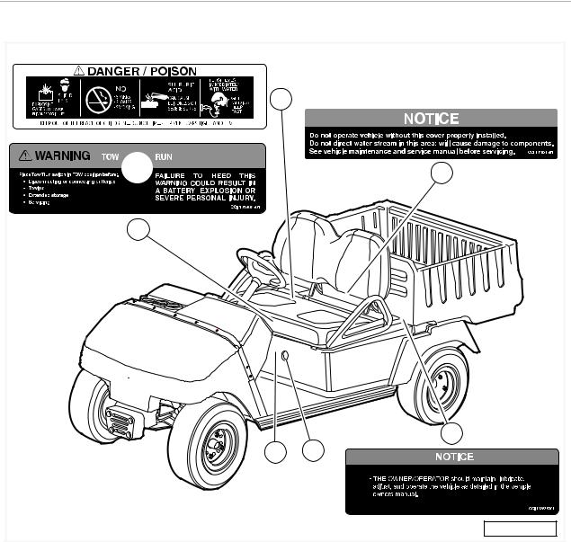
SAFETY DECAL AND FEATURE IDENTIFICATION
The following pages contain safety decal and feature identification information. For detailed information on specific features, read the appropriate section in this manual.
Page 4 2008 Husqvarna 4210-G, 4210-E, 4210-GXP, and 4210-EXP Owner’s Manual
Safety Decal and Feature Identification
HUV4210-E ELECTRIC VEHICLE |
|
1 |
|
|
3 |
2 |
|
|
4 |
6 |
5 |
|
279 |
1 |
1013677 |
Decal, Battery Danger (on battery caps or on body |
11 |
|
|
under seat) |
|
|
|||
|
|
|
|
|
|
|
|
|
|
|
|
2 |
101908601 |
Decal, Tow Switch Warning (on Tow/Run switch plate, |
12 |
|
|
under seat) |
|
|
|||
|
|
|
|
|
|
|
|
|
|
|
|
3 |
101931501 |
Decal, Component Cover Notice (on electrical compo- |
13 |
|
|
|
|
nent cover) |
|
|
|
4 |
102833301 |
Decal, Maintenance Notice (on vehicle body, under |
14 |
|
|
bed) |
|
|
|||
|
|
|
|
|
|
|
|
|
|
|
|
5 |
|
Battery Charger Receptacle |
15 |
|
|
|
|
|
|
|
|
6 |
|
Forward/Reverse Control |
16 |
|
|
|
|
|
|
|
|
7 |
|
|
17 |
|
|
|
|
|
|
|
|
8 |
|
|
18 |
|
|
|
|
|
|
|
|
9 |
|
|
19 |
|
|
|
|
|
|
|
|
10 |
|
|
20 |
|
|
|
|
|
|
|
|
|
|
|
|
|
|
2008 Husqvarna 4210-G, 4210-E, 4210-GXP, and 4210-EXP Owner’s Manual |
Page 5 |

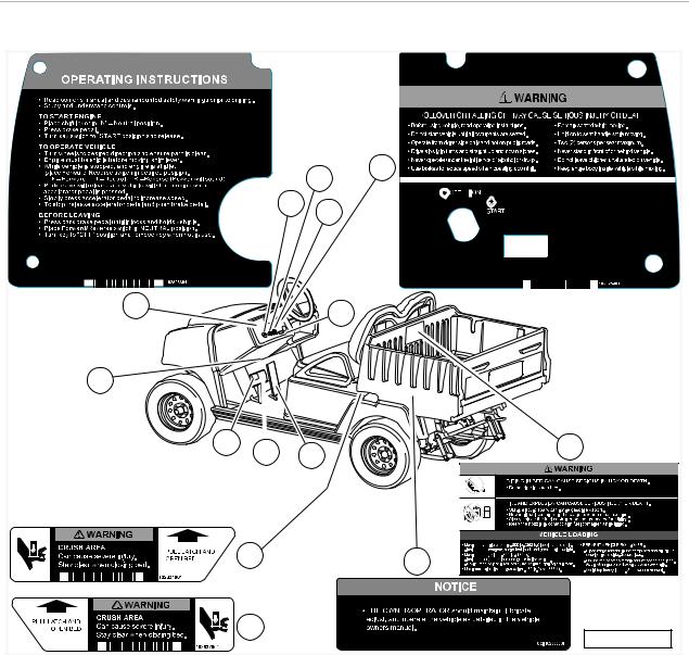
Safety Decal and Feature Identification
HUV4210-E ELECTRIC VEHICLE |
|
|
8 |
|
|
9 |
1 |
|
7 |
|
|
2 |
|
|
|
10 |
|
6 |
|
|
13 |
5 |
|
11 |
||
12 |
||
|
||
3 |
|
|
4 |
|
|
|
280 |
1 |
102825501 |
Decal, Rollover Warning (on instrument panel) |
11 |
|
Accelerator Pedal |
|
|
|
|
|
|
2 |
102825701 |
Decal, Operating Instructions (on instrument panel) |
12 |
|
Brake Pedal |
|
|
|
|
|
|
3 |
102831901 |
Decal, Bed Latch Warning (on vehicle body, below |
13 |
|
Park Brake Pedal |
bed latch) |
|
||||
|
|
|
|
|
|
|
|
|
|
|
|
4 |
102832001 |
Decal, Bed Latch Warning (on vehicle body, below |
14 |
|
|
bed latch) |
|
|
|||
|
|
|
|
|
|
|
|
|
|
|
|
5 |
|
Vehicle Loading Instructions |
15 |
|
|
|
|
|
|
|
|
6 |
|
Serial Number |
16 |
|
|
|
|
|
|
|
|
7 |
|
Battery Condition Indicator |
17 |
|
|
|
|
|
|
|
|
8 |
|
Light Switch |
18 |
|
|
|
|
|
|
|
|
9 |
|
Key Switch |
19 |
|
|
|
|
|
|
|
|
10 |
|
Battery Warning Light |
20 |
|
|
|
|
|
|
|
|
|
|
|
|
|
|
Page 6 2008 Husqvarna 4210-G, 4210-E, 4210-GXP, and 4210-EXP Owner’s Manual
Safety Decal and Feature Identification
HUV4210-E GASOLINE VEHICLE |
|
|
1 |
|
9 |
|
8 |
|
10 |
2 |
11 |
|
|
7 |
|
14 |
6 |
13 |
12 |
|
|
3 |
5 |
|
|
4 |
281 |
|
1 |
102825401 |
Decal, Rollover Warning (on instrument panel) |
11 |
|
Low Oil Warning Light |
|
|
|
|
|
|
2 |
102825601 |
Decal, Operating Instructions (on instrument panel) |
12 |
|
Accelerator Pedal |
|
|
|
|
|
|
3 |
102831901 |
Decal, Bed Latch Warning (on vehicle body, below |
13 |
|
Brake Pedal |
bed latch) |
|
||||
|
|
|
|
|
|
|
|
|
|
|
|
4 |
102832001 |
Decal, Bed Latch Warning (on vehicle body, below |
14 |
|
Park Brake Pedal |
bed latch) |
|
||||
|
|
|
|
|
|
|
|
|
|
|
|
5 |
102833301 |
Decal, Maintenance Notice (on vehicle body, under |
15 |
|
|
bed) |
|
|
|||
|
|
|
|
|
|
|
|
|
|
|
|
6 |
|
Vehicle Loading Instructions |
16 |
|
|
|
|
|
|
|
|
7 |
|
Serial Number |
17 |
|
|
|
|
|
|
|
|
8 |
|
Fuel Gauge |
18 |
|
|
|
|
|
|
|
|
9 |
|
Light Switch |
19 |
|
|
|
|
|
|
|
|
10 |
|
Key Switch |
20 |
|
|
|
|
|
|
|
|
|
|
|
|
|
|
2008 Husqvarna 4210-G, 4210-E, 4210-GXP, and 4210-EXP Owner’s Manual |
Page 7 |
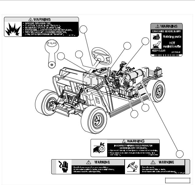
Safety Decal and Feature Identification
HUV4210-E GASOLINE VEHICLE |
|
|
1 |
|
3 |
|
7 |
5 |
6 |
|
|
|
4 |
|
8 |
|
2 |
|
282 |
1 |
101547601 |
Decal, Gasoline Fuel Warning (at fuel fill or on frame, |
11 |
|
|
near fuel tank) |
|
|
|||
|
|
|
|
|
|
|
|
|
|
|
|
2 |
101915201 |
Decal, Frame Ground/Governor Warning (on vehicle |
12 |
|
|
frame near battery) |
|
|
|||
|
|
|
|
|
|
|
|
|
|
|
|
3 |
101960501 |
Decal, Rotating Parts/Hot Manifold Warning (on |
13 |
|
|
engine, starter/generator, and transaxle) |
|
|
|||
|
|
|
|
|
|
|
|
|
|
|
|
4 |
102345901 |
Decal, Diode Safety Warning (on vehicle frame, near |
14 |
|
|
diode) |
|
|
|||
|
|
|
|
|
|
|
|
|
|
|
|
5 |
|
Forward/Reverse Control |
15 |
|
|
|
|
|
|
|
|
6 |
|
Fuel Shut-Off Valve |
16 |
|
|
|
|
|
|
|
|
7 |
|
Oil Fill |
17 |
|
|
|
|
|
|
|
|
8 |
|
Choke |
18 |
|
|
|
|
|
|
|
|
9 |
|
|
19 |
|
|
|
|
|
|
|
|
10 |
|
|
20 |
|
|
|
|
|
|
|
|
|
|
|
|
|
|
Page 8 2008 Husqvarna 4210-G, 4210-E, 4210-GXP, and 4210-EXP Owner’s Manual
Practice Safety
PRACTICE SAFETY
Figure 1 Practice Safety
Safety signs like you see above may at first seem shocking, but their impact is mild compared with the reality of severe personal injury.
Your safety and satisfaction are of the utmost importance to us. That is why before operating the vehicle, we urge you to review the information in this manual. Understand and become familiar with the DANGER, WARNING, and CAUTION statements and procedures it contains, along with the safety decals that are affixed to your vehicle.
Take time to understand the language of safety. It is a language that can save your life.
PROPOSITION 65 – STATE OF CALIFORNIA
ýWARNING
•This product contains or emits chemicals or substances that have been determined by the state of California to cause cancer and birth defects or other reproductive harm.
2008 Husqvarna 4210-G, 4210-E, 4210-GXP, and 4210-EXP Owner’s Manual |
Page 9 |

Safety Details
SAFETY DETAILS
ýWARNING
•This owner’s manual should be read completely before attempting to drive or service the vehicle. Failure to follow the instructions in this manual could result in property damage, severe personal injury, or death.
It is important to note that some vital statements throughout this manual and on the decals affixed to the vehicle are preceded by the words DANGER, WARNING, or CAUTION. For your protection, we recommend that you take special notice of these safety precautions. Safety precautions are essential and must be followed.
If any of the operation or warning decals on the vehicle become damaged, have been removed or cannot be easily read, they should be replaced immediately to avoid possible property damage, personal injury, or death. Contact your Husqvarna dealer.
ýDAN GE R
•A DANGER indicates an immediate hazard that will result in severe personal injury or death.
ýWARNING
•A WARNING indicates an immediate hazard that could result in severe personal injury or death.
ýCAUT ION
•A CAUTION with the safety alert symbol indicates a hazard or unsafe practice that could result in minor personal injury.
CAUT ION
•A CAUTION without the safety alert symbol indicates a potentially hazardous situation that could result in property damage.
GENERAL WARNINGS
The following safety statements must be heeded whenever the vehicle is being operated, repaired, or serviced. See Safety Decal and Feature Identification on page 4. Other specific safety statements appear throughout this manual and on the vehicle.
ýDAN GE R
•Battery – Explosive gases! Do not smoke. Keep sparks and flames away from the vehicle and service area. Ventilate when charging or operating vehicle in an enclosed area. Wear a full face shield and rubber gloves when working on or near batteries.
•Gasoline – Flammable! Explosive! Do not smoke. Keep sparks and flames away from the vehicle and service area. Service only in a well-ventilated area.
DANGER CONTINUED ON NEXT PAGE...
Page 10 2008 Husqvarna 4210-G, 4210-E, 4210-GXP, and 4210-EXP Owner’s Manual

General Warnings
ýDAN GE R
•Do not operate engine in an enclosed area without proper ventilation. The engine produces carbon monoxide, which is an odorless, deadly poison.
•The vehicle will not provide protection from lightning, flying objects, or other storm-related hazards. If caught in a storm while driving a Husqvarna vehicle, exit the vehicle and seek shelter in accordance with applicable safety guidelines for your location.
ýWARNING
•Follow the procedures exactly as stated in this manual, and heed all DANGER, WARNING, and CAUTION statements in this manual as well as those on the vehicle and battery charger.
•Do not leave children unattended on vehicle.
•Prior to leaving the vehicle unattended or servicing the vehicle, set the park brake, place the Forward/Reverse handle or switch in the NEUTRAL position, turn the key switch to the OFF position, and remove the key. Chock the wheels when servicing the vehicle.
•Improper use of the vehicle or failure to properly maintain it could result in decreased vehicle performance, severe personal injury, or death.
•Any modification or change to the vehicle that affects the stability or handling of the vehicle, or increases maximum vehicle speed beyond factory specifications, could result in severe personal injury or death.
•Do not operate the vehicle without an installed front bumper or brush guard that is specifically designed and approved for use on this vehicle. Instability in the vehicle could cause serious injury or death (Figure 3 and Figure 4).
•Check the vehicle for proper location of all vehicle safety and operation decals and make sure they are in place and are easy to read.
•For vehicles with cargo beds, remove all cargo before raising the bed or servicing the vehicle. If the vehicle is equipped with a prop rod, ensure that it is securely engaged while bed is raised. Do not close bed until all persons are clear of cargo bed area. Keep hands clear of all crush areas. Do not drop cargo bed; lower gently and keep entire body clear. Failure to heed this warning could result in severe personal injury or death.
•Only trained technicians should service or repair the vehicle or battery charger. Anyone doing even simple repairs or service should have knowledge and experience in electrical and mechanical repair. The appropriate instructions must be used when performing maintenance, service, or accessory installation.
Gasoline vehicles:
•To avoid unintentionally starting the vehicle:
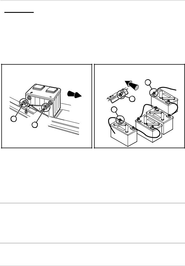
-Disconnect battery cables, negative (–) cable first (Figure 1).
-Disconnect the spark plug wire from the spark plug.
•Frame ground – Do not allow tools or other metal objects to contact frame when disconnecting battery cables or other electrical wiring. Do not allow a positive wire to touch the vehicle frame, engine, or any other metal component.
Electric vehicles:
•Place Tow/Run switch in the TOW position before disconnecting or connecting the batteries. Failure to heed this warning could result in a battery explosion or severe personal injury.
•To avoid unintentionally starting the vehicle, disconnect the batteries as shown (Figure 2, Page 12).
•After disconnecting the batteries, wait 90 seconds for the controller capacitors to discharge.
WARNING CONTINUED ON NEXT PAGE...
2008 Husqvarna 4210-G, 4210-E, 4210-GXP, and 4210-EXP Owner’s Manual |
Page 11 |
General Information
ý WARNING
•Use insulated tools when working near batteries or electrical connections. Use extreme caution to avoid shorting of components or wiring.
All vehicles:
•Wear safety glasses or approved eye protection when servicing the vehicle or battery charger. Wear a full face shield and rubber gloves when working on or near batteries.
•Do not wear loose clothing or jewelry such as rings, watches, chains, etc., when servicing the vehicle or battery charger.
2 |
(+) |
1 |
(–) |
Figure 1 Gasoline Vehicle
(Viewed from passenger side of vehicle)
1.Remove negative battery cable.
2.Remove positive battery cable. Connect battery cables in reverse order.
|
3 |
|
(+) |
|
1 |
2 |
1 |
|
(–) |
|
2 |
|
3 |
|
4 |
Figure 2 IQ System Electric Vehicle - 12-Volt Battery
Configuration
(Viewed from driver side of vehicle)
1.Place TOW/RUN Switch in TOW before disconnecting or connecting battery cables.
2.Remove negative battery cable.
3.Remove positive battery cable.
Connect battery cables in reverse order.
GENERAL INFORMATION
This manual features two models: the electric vehicle and the gasoline vehicle. Throughout this manual, important features unique to each model are highlighted. We urge the owner/operator to read and understand this manual, and to pay special attention to the features specific to his/her vehicle(s).
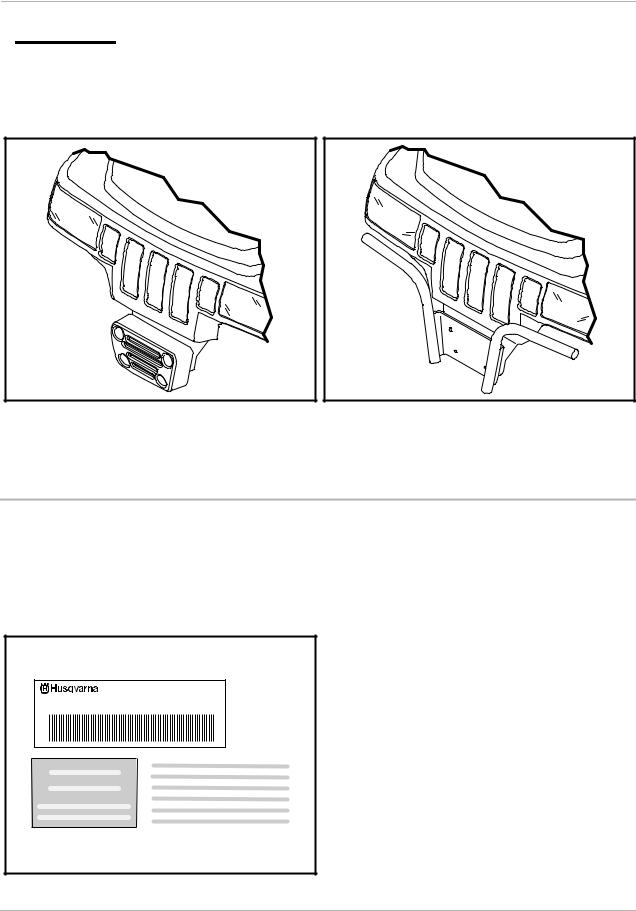
FRONT BUMPER AND BRUSH GUARD
The front bumper and brush guard are an important part of the vehicle’s design for correct weight distribution. These parts are interchangeable, but one or the other must be installed at all times during vehicle operation to achieve proper balance (Figure 3 and Figure 4). See following WARNING.
Page 12 2008 Husqvarna 4210-G, 4210-E, 4210-GXP, and 4210-EXP Owner’s Manual
Model Identification
ýWARNING
•Do not operate the vehicle without an installed front bumper or brush guard that is specifically designed and approved for use on this vehicle. Instability in the vehicle could cause serious injury or death.
Figure 3 Bumper |
Figure 4 Brush Guard |
MODEL IDENTIFICATION
The serial number of the vehicle is printed on a bar code decal mounted on the frame directly above the accelerator pedal (Example: HH0601-583947) (Figure 5). There is also a second serial number decal mounted on the front frame behind the dash. The dash must be removed to view this decal. See following NOTE.
NOTE: Have the vehicle serial number available when ordering parts or making inquiries.
|
SERIAL NUMBER |
7349 STATESVILLE RD. |
HH0601-583947 |
CHARLOTTE, NC 28269 |
Figure 5 Gas Vehicle Serial Number
2008 Husqvarna 4210-G, 4210-E, 4210-GXP, and 4210-EXP Owner’s Manual |
Page 13 |

Controls and Indicators
CONTROLS AND INDICATORS
See General Warnings on page 10.
ýWARNING
•If renting or loaning the vehicle, make sure the driver is familiar with all controls and operating procedures before allowing the vehicle to be driven.
•Do not shift the Forward/Reverse handle or switch while the vehicle is moving. To avoid injury to an unsuspecting passenger or damage to the vehicle, always bring the vehicle to a full stop before shifting the Forward/Reverse handle or switch.
•Release the accelerator pedal and then press the brake pedal firmly until the vehicle stops. To avoid unintentionally starting or rolling the vehicle, set the park brake, place the Forward/ Reverse handle or switch in the NEUTRAL position, turn the key switch to the OFF position, and remove the key when leaving the vehicle.
•Gasoline vehicles only: Do not tamper with the governor. Doing so will void the warranty, as well as damage the engine and other components, and could result in property damage, personal injury, or death due to unsafe speeds.
KEY SWITCH
Gasoline Vehicles
The key switch is mounted on the dash to the right of the steering column (Figure 6). It has three positions, OFF, ON and START. To start the vehicle, place the Forward/Reverse handle in the NEUTRAL position and turn the key past the ON position to the START position and hold until the engine is running smoothly. When the engine is cold it may be necessary to use the choke. See Choke on page 19. Release the key and it will return to the ON position and the engine should idle. The engine will continue to idle until the key is turned to the OFF position. See following WARNING, CAUTION and NOTE.
ýWARNING
•Moving parts! Keep clear of the engine compartment while the engine is running.
CAUT ION
•Do not “rev” the engine for long periods of time while the Forward/Reverse handle is in the NEUTRAL position. Failure to heed this caution could result in damage to the unitized transaxle.
•Do not shift the Forward/Reverse handle while the accelerator pedal is pressed. Shift the handle only when the vehicle is at a complete stop. Failure to heed this caution could result in damage to the unitized transaxle.
NOTE: The key can be removed only when the key switch is in the OFF position.
Page 14 2008 Husqvarna 4210-G, 4210-E, 4210-GXP, and 4210-EXP Owner’s Manual

Controls and Indicators
2 |
1 |
|
Figure 6 Key Switch – Gasoline Vehicle
Electric Vehicles
The key switch is mounted on the dash to the right of the steering column. It has two positions, OFF and ON, which are clearly labeled. See following NOTE.
NOTE: The key can be removed only when the key switch is in the OFF position.
FORWARD/REVERSE CONTROL Gasoline Vehicles
The Forward/Reverse handle is located on the seat support panel (Figure 7). The handle has three distinct positions: F (FORWARD), N (NEUTRAL), and R (REVERSE). Rotate the handle towards the driver (FORWARD) to operate the vehicle in the forward direction, or towards the passenger (REVERSE) to operate the vehicle in reverse. Husqvarna vehicles operate at reduced speed in REVERSE. The engine can be started only when the handle is in the straight up position (NEUTRAL). The engine must be at idle before shifting the Forward/Reverse handle. See WARNING and CAUTION on page 14.
Electric Vehicles
The Forward/Reverse rocker switch is located on the seat support panel (Figure 8). The F (FORWARD) and R (REVERSE) positions are clearly marked. Push down the FORWARD side of the switch to operate the vehicle in the forward direction, or push down the REVERSE side of the switch to operate the vehicle in reverse. When the rocker switch is positioned in the NEUTRAL position, with neither side down, the vehicle will not operate if the accelerator pedal is pressed. The reverse buzzer will sound as a warning when the Forward/ Reverse switch is in the REVERSE position. Husqvarna vehicles operate at reduced speed in REVERSE.
2008 Husqvarna 4210-G, 4210-E, 4210-GXP, and 4210-EXP Owner’s Manual |
Page 15 |

Controls and Indicators
Figure 7 Forward/Reverse Handle –
Gas Vehicle
Figure 9 Accelerator and Brake Pedals
Figure 8 Forward/Reverse Rocker Switch –
Electric Vehicle
ACCELERATOR PEDAL
The accelerator pedal is the pedal on the right, with the word GO molded into it (Figure 9).
Electric Vehicles
The operation of the accelerator pedal differs from that of an automobile. When the key switch is in the ON position, and the Forward/Reverse switch is in either the FORWARD or REVERSE position, pressing the accelerator pedal will automatically release the park brake and start the vehicle moving in the direction selected (forward or reverse). As the accelerator pedal is pressed, speed will increase until full speed is reached. When the accelerator is released, power will be cut off and the motor will stop running.
Electric vehicles use a special system, which employs motor braking in some modes of operation. In those modes, the vehicle operates as follows:
Gasoline Vehicles
After starting the engine with the key switch and placing the Forward/Reverse handle in the FORWARD position, the vehicle should accelerate smoothly to full speed as the accelerator pedal is pressed. When the pedal is released it should return to the original position and the engine should idle.
Page 16 2008 Husqvarna 4210-G, 4210-E, 4210-GXP, and 4210-EXP Owner’s Manual

Controls and Indicators
BRAKE PEDAL
The brake pedal is the large pedal on the left with the word STOP molded into it (Figure 9). To slow or stop the vehicle, press the brake pedal with your foot (Figure 10).
Figure 10 Brake Pedal |
Figure 11 Park Brake Pedal |
PARK BRAKE PEDAL
The park brake pedal is the small raised portion in the upper left corner of the brake pedal. It has the word PARK molded into it and the words PARK BRAKE marked on top of it (Figure 10). To set the park brake, press the brake pedal firmly and tilt the park brake portion of the pedal forward with your foot (Figure 11). See following WARNING.
ýWARNING
•The park brake will release automatically when either the accelerator or brake pedal is pressed. The park brake has multiple locking positions and should be firmly pressed and locked to prevent the vehicle from rolling.
BATTERY WARNING LIGHT
Electric Vehicles Only
Electric vehicles feature a dash-mounted warning light (to the right of the key switch) that, when the vehicle is in operation, indicates low battery voltage or, when the vehicle is being charged, indicates a charging problem. The warning light is controlled by the onboard computer.
When the vehicle is in operation, the warning light will illuminate and remain illuminate if:
•Batteries’ voltage drops below 48 volts when there is no load on the batteries (the vehicle is stopped and there are no accessories on).
•Batteries have discharged to less than 25% of rated capacity.
If the warning light illuminates when the vehicle is operating, there will be enough power remaining to drive the vehicle for approximately 30 minutes. However, the vehicle should be charged at the first opportunity. If the warning light illuminates and the vehicle is unable to operate for 30 minutes, have your Husqvarna distributor/ dealer check the vehicle for a possible battery or electrical system problem.
When the batteries receive an incomplete charge because 1) the DC power cord is disconnected, 2) AC power to the charger is interrupted, 3) automatic charger shut-off occurs after 16 hours of operation, or 4) the charger malfunctions, the warning light will indicate as follows:
2008 Husqvarna 4210-G, 4210-E, 4210-GXP, and 4210-EXP Owner’s Manual |
Page 17 |

Controls and Indicators
•The warning light will not illuminate if the charge is 90% or more complete. The onboard computer will retain in memory the amount of charge needed to fully replenish the batteries and will complete the charge during the next charge cycle.
•When the charger is unplugged, the warning light will illuminate and remain illuminated for 10 seconds if the charge is less than 90% complete but the vehicle has enough power for approximately 30 minutes of operation. This will alert the operator that the vehicle may be used, but that it must be charged to completion as soon as possible.
•The warning light will repeatedly illuminate for 10 seconds, with 4 second intervals if the charger times out at 16 hours and the batteries are not sufficiently charged. See the battery charger owner’s manual. This indicates an abnormal charge cycle. The charger and batteries should be checked by your Husqvarna distributor/dealer.
•The warning light will repeatedly illuminate for 10 seconds, with 4 second intervals during a charge cycle (DC plug is still connected) if AC power to the charger is interrupted. The light will go out when AC power is restored.
LED Light: In addition to the warning light, there is an infrared LED in the dash light assembly, which transmits an infrared signal from the onboard computer (OBC). This signal is received by the optional Communication Display Module (Husqvarna 603 00 18-63), which provides information on the condition of the vehicle and batteries.
TOW/RUN SWITCH
Electric Vehicles Only
ýWARNING
•Place Tow/Run switch in the TOW position before disconnecting or connecting the batteries. Failure to heed this warning could result in a battery explosion or severe personal injury.
•When the Tow/Run switch is in the TOW position, all motor braking functions, including zero speed detect, are disabled.
Electric vehicles are equipped with a Tow/Run switch, located under the seat just above the Forward/Reverse switch (Figure 12). The switch must be in the RUN position in order to operate the vehicle. When the switch is in the TOW position, power to the vehicle electrical components is turned off and the vehicle will not operate. See following NOTE.
NOTE: After placing the Tow/Run switch in the TOW position, allow 10 seconds to elapse before switching back to the RUN position.
After placing the Tow/Run switch in the RUN position, allow 10 seconds to elapse before operating the vehicle.
The Tow/Run switch should be placed in the TOW position under the following conditions:
•Before Towing the Vehicle: Place the Tow/Run switch in the TOW position to disable all motor braking functions, thus preventing possible damage that could occur to the vehicle or electrical components if the vehicle is towed while the zero speed detect motor braking function is operating.
•Before Disconnecting or Connecting Battery Cables: Place the Tow/Run switch in the TOW position to turn off power to the vehicle electrical system, thus preventing severe arcing and possible battery explosion as the battery cables are disconnected.
•For Long Term Storage: Place the Tow/Run switch in the TOW position to turn off power to the vehicle electrical system, thus preventing vehicle electrical components from discharging the batteries.
Page 18 2008 Husqvarna 4210-G, 4210-E, 4210-GXP, and 4210-EXP Owner’s Manual
Loading...